US5048789A - Microphone stand - Google Patents
Microphone stand Download PDFInfo
- Publication number
- US5048789A US5048789A US07/459,567 US45956790A US5048789A US 5048789 A US5048789 A US 5048789A US 45956790 A US45956790 A US 45956790A US 5048789 A US5048789 A US 5048789A
- Authority
- US
- United States
- Prior art keywords
- upright
- base member
- microphone stand
- stand
- base
- Prior art date
- Legal status (The legal status is an assumption and is not a legal conclusion. Google has not performed a legal analysis and makes no representation as to the accuracy of the status listed.)
- Expired - Lifetime
Links
Images


Classifications
-
- F—MECHANICAL ENGINEERING; LIGHTING; HEATING; WEAPONS; BLASTING
- F16—ENGINEERING ELEMENTS AND UNITS; GENERAL MEASURES FOR PRODUCING AND MAINTAINING EFFECTIVE FUNCTIONING OF MACHINES OR INSTALLATIONS; THERMAL INSULATION IN GENERAL
- F16M—FRAMES, CASINGS OR BEDS OF ENGINES, MACHINES OR APPARATUS, NOT SPECIFIC TO ENGINES, MACHINES OR APPARATUS PROVIDED FOR ELSEWHERE; STANDS; SUPPORTS
- F16M11/00—Stands or trestles as supports for apparatus or articles placed thereon Stands for scientific apparatus such as gravitational force meters
- F16M11/02—Heads
- F16M11/04—Means for attachment of apparatus; Means allowing adjustment of the apparatus relatively to the stand
- F16M11/06—Means for attachment of apparatus; Means allowing adjustment of the apparatus relatively to the stand allowing pivoting
- F16M11/10—Means for attachment of apparatus; Means allowing adjustment of the apparatus relatively to the stand allowing pivoting around a horizontal axis
-
- F—MECHANICAL ENGINEERING; LIGHTING; HEATING; WEAPONS; BLASTING
- F16—ENGINEERING ELEMENTS AND UNITS; GENERAL MEASURES FOR PRODUCING AND MAINTAINING EFFECTIVE FUNCTIONING OF MACHINES OR INSTALLATIONS; THERMAL INSULATION IN GENERAL
- F16M—FRAMES, CASINGS OR BEDS OF ENGINES, MACHINES OR APPARATUS, NOT SPECIFIC TO ENGINES, MACHINES OR APPARATUS PROVIDED FOR ELSEWHERE; STANDS; SUPPORTS
- F16M11/00—Stands or trestles as supports for apparatus or articles placed thereon Stands for scientific apparatus such as gravitational force meters
- F16M11/20—Undercarriages with or without wheels
- F16M11/24—Undercarriages with or without wheels changeable in height or length of legs, also for transport only, e.g. by means of tubes screwed into each other
- F16M11/26—Undercarriages with or without wheels changeable in height or length of legs, also for transport only, e.g. by means of tubes screwed into each other by telescoping, with or without folding
- F16M11/28—Undercarriages for supports with one single telescoping pillar
-
- H—ELECTRICITY
- H04—ELECTRIC COMMUNICATION TECHNIQUE
- H04R—LOUDSPEAKERS, MICROPHONES, GRAMOPHONE PICK-UPS OR LIKE ACOUSTIC ELECTROMECHANICAL TRANSDUCERS; DEAF-AID SETS; PUBLIC ADDRESS SYSTEMS
- H04R1/00—Details of transducers, loudspeakers or microphones
- H04R1/08—Mouthpieces; Microphones; Attachments therefor
-
- F—MECHANICAL ENGINEERING; LIGHTING; HEATING; WEAPONS; BLASTING
- F16—ENGINEERING ELEMENTS AND UNITS; GENERAL MEASURES FOR PRODUCING AND MAINTAINING EFFECTIVE FUNCTIONING OF MACHINES OR INSTALLATIONS; THERMAL INSULATION IN GENERAL
- F16M—FRAMES, CASINGS OR BEDS OF ENGINES, MACHINES OR APPARATUS, NOT SPECIFIC TO ENGINES, MACHINES OR APPARATUS PROVIDED FOR ELSEWHERE; STANDS; SUPPORTS
- F16M2200/00—Details of stands or supports
- F16M2200/08—Foot or support base
-
- Y—GENERAL TAGGING OF NEW TECHNOLOGICAL DEVELOPMENTS; GENERAL TAGGING OF CROSS-SECTIONAL TECHNOLOGIES SPANNING OVER SEVERAL SECTIONS OF THE IPC; TECHNICAL SUBJECTS COVERED BY FORMER USPC CROSS-REFERENCE ART COLLECTIONS [XRACs] AND DIGESTS
- Y10—TECHNICAL SUBJECTS COVERED BY FORMER USPC
- Y10T—TECHNICAL SUBJECTS COVERED BY FORMER US CLASSIFICATION
- Y10T403/00—Joints and connections
- Y10T403/70—Interfitted members
- Y10T403/7009—Rotary binding cam or wedge
- Y10T403/7011—Radially interposed shim or bushing
Definitions
- This invention relates to upright support stands. More particularly, this invention relates to support stands of the type including a base member and an upright member secured to the base member. Even more particularly, this invention relates to microphone stands or the like.
- Support stands of various types are known and have been used for a variety of purposes. In the music and entertainment fields, support stands are used for supporting items such as microphones, speakers, lights, etc.
- support stands are adjustable as to height.
- many support stands include a telescoping upright member.
- a lock or catch means is used to hold the uppermost portion of the upright in a desired position.
- Some types of locks and catches work better than others.
- a base member used to support the upright member.
- a base previously used is a solid, heavy metal base (usually made of cast iron). Such bases are bulky and cumbersome. Consequently, they are not easy to carry or transport.
- Another common style of a base which has been used is a steel tripod whose legs fold or collapse downwardly. The tripod is releasably secured to the stand (for example, with a wing nut which may be loosened, thereby allowing the folded tripod base to slide upwardly along the stand).
- the tripod base is a separate unit which must be securely fastened to the stand in order to support the stand in a stable manner.
- a tilting disk at the bottom of the vertically adjustable section of the stand.
- the tilting disk is designed to prevent the adjustable section from being pulled downwardly by gravity but it does not restrict upward movement of such section.
- a movable knob at the upper end of the stand is designed to tilt and release the disk to allow downward movement of the adjustable section.
- an improved support stand (such as a microphone stand or the like) comprising a base member and an upright member secured to the base.
- the base is designed such that support stands of the same design can be stacked upon each other without disassembly.
- the support stand includes a telescoping upright member, i.e., two upright sections which are slidably engaged.
- the lowermost section is secured to the base member, and the riser member is slidably received in the lowermost section and can be moved vertically.
- the uppermost section (a riser member) can be locked in any desired position.
- At the upper end of the lowermost section there is a clutch member (which may include a slot which extends longitudinally).
- a collar member carried by the upper end of the lowermost section can be rotated between locked and unlocked positions to thereby control locking and unlocking of the riser member in a desired position.
- the support stands of the invention are especially useful as microphone stands or the like.
- Preferred stands include a base member which enables like stands to be stacked upon each other, and such stands also include a vertically adjustable riser member.
- a glide carried by the lower end of the riser member facilitates smooth and quiet movement relative to the upright member and also eliminates a pinch point between the upper ends of the riser member and the upright member.
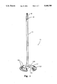
- FIG. 1 is a perspective view of a preferred embodiment of the support stand of the invention
- FIG. 2 is a top view of the support stand shown in FIG. 1;
- FIG. 3 is a partially cut-away, cross-sectional view illustrating the stackable feature of the invention
- FIG. 3A is a bottom view of the stand shown in FIG. 1;
- FIG. 4 is a cross-sectional view illustrating one embodiment of the support stand of the invention which includes a telescoping upright member
- FIG. 5 is a side elevational view of one type of clutch member which is useful in the present invention.
- FIG. 6 is a cross-sectional view of the clutch member show in FIG. 5;
- FIG. 7 is a cross-sectional view illustrating a preferred type of rotatable collar member
- FIG. 8 is a side elevational view, partially cut-away, of a preferred embodiment of microphone stand of the invention.
- FIGS. 9-18 are top views illustrating other shapes of base members which are useful in the present invention.
- support stand 10 of the invention comprising a base member 12 and an elongated upright member 14.
- the upright member is tubular and preferably is perpendicular to the base member.
- riser member 16 which is slidably received in the upper end of upright member 14.
- a rotatable collar member 18 is carried on the upper end of the upright member and is adapted to lock the riser member in any desired vertical position.
- the support stand of the invention is useful for a variety of purposes. For example, it is especially useful for supporting a microphone, speaker, lights, camera equipment, telescopes, sheet music, microphone booms, tables, and the like. The preferred use is for supporting a microphone.
- the base member 12 is a disc which includes a radial slot 12A which extends from the edge of the base inwardly a distance at least equal to the radius of the base member.
- the slot 12A preferably includes parallel sides, as illustrated.
- the width of the slot 12A is at least about 35% of the width of the base member and may be as much as 50% thereof, for example.
- the purpose of the slot 12A in the base member is to enable the support stands to be stacked upon each other.
- the slot 12A enables the upright member of a lower support stand to extend through the base member of an upper support stand. In this manner several similar support stands can be stacked on top of each other such that the base of the upper stand is directly over the base of the lower stand.
- FIG. 3 illustrates two support stands in stacked arrangement.
- base member 12 includes a central portion 12B which is higher than the outward portion 12C.
- Step members 12E are spaced around the periphery of the base 12, as illustrated, to facilitate nesting of the stacked base members.
- the underside of each base member includes a downwardly projecting rim member 12D which is adapted to rest upon the step members 12E of the base member below it.
- the underside of the base member 12 includes downwardly projecting rim member 12D. At spaced intervals along rim 12D there are detents or recessed areas 12F.
- the spacing between adjacent detents 12F corresponds to the spacing between adjacent step members 12E so that when one support stand is stacked upon another of like design, the detents 12F on the underside of the upper base will engage the step members 12E on the upper side of the lower base.
- the depth of the detents or recessed areas 12F may vary.
- the width of each area 12F is generally only slightly greater than the width of a step member 12E.
- the presence of the detents or recessed areas assists in aligning the several stands in proper position for maximum stacking quantity (e.g., six stands of the design shown in FIG. 1).
- the stand of FIG. 1 includes six steps 12E and six detents or recessed areas 12F. Six stands of this type could still be stacked upon each other with only one step member and one detent, if desired.
- the detents are not required to be present at all, although it is preferred to include them.
- the riser member 16 is slidably received in the upper end of the tubular upright member 14. As shown in FIG. 4, a tubular clutch member or receiver 20 is carried by the upper end of the upright 14. The clutch member or receiver is also shown in FIGS. 5 and 6.
- the clutch member 20 preferably includes a longitudinal slot 20A, and also includes at least one, and preferably two, outwardly projecting ridge members 20C on opposite sides thereof. To hold the clutch member in place, it includes an outwardly projecting tab member 20B which extends into an appropriate aperture in the wall of the tubular member 14. The clutch member 20 can be squeezed slightly so as to reduce the diameter thereof so that it can be slidingly received in the open upper end of the tubular member 14. Then when the tab member 20B is in alignment with the aperture in the wall of tubular member 14, the clutch member 20 can be allowed to spring back toward its original shape and the tab 20B extends into the aperture. Then the riser member 16 can be inserted through the clutch member or receiver 20, as illustrated in FIG. 4. Because of the close fit between the riser 16 and the clutch or receiver 20, the receiver 20 is prevented from becoming disengaged from the upper end of the tubular member 14. No separate fasteners are required to hold the receiver 20 to the upright member 14 in the preferred embodiment illustrated.
- Collar 18 Acting in cooperation with the clutch member or receiver 20 is the collar 18 which is also carried by the upper end of the upright 14.
- Collar 18 includes at least one (and preferably two) cam members 18A which are adapted to engage the outwardly projecting ridge members 20C on the clutch member 20.
- cam members 18A When the cam members engage the ridge members (by simple rotation of collar 18) the clutch member is squeezed and thereby made smaller in diameter. The reduction in diameter of the clutch member causes it to grip the riser member 16 and lock it in place relative to the upright member 14. Rotation of the collar 18 in the opposite direction enables the clutch 20 to return to its original condition out of engagement with the riser 16.
- FIG. 8 illustrates a preferred embodiment of microphone stand of the invention in which a microphone clip 30 is secured to the upper end of riser member 16.
- a glide member 17 which is composed of plastic (e.g., high density polyethylene) and which includes wing members 17A which extend outwardly and engage the inner wall of upright 14.
- the presence of glide member 17 serves to center the riser 16 within tubular member 14 and also serves to limit the extent to which riser 16 may extend downwardly into upright 14.
- the upper end of riser 16 is prevented from contacting the upper end of collar 18. This eliminates a pinch point.
- Another manner of limiting the extent of downward travel of the riser member is to reduce the diameter of the tubular member 14 at a desired location where the lower end of the riser member will then be prevented from traveling past.
- the lower end of the upright member 14 may be secured to the base member in a variety of manners.
- a preferred manner is to provide a tapered opening in the base member to receive a tapered lower end of the upright member.
- a threaded bolt or screw may then extend through the base and into the lower end of the riser to secure the upright to the base.
- FIG. 9 shows a triangular shape with a generally square-shaped slot or opening extending from one side edge toward the upright member 40.
- the upright member has been designated as 40. It is perpendicular to the base in all instances shown in the drawings, although it is not required that the upright member be perpendicular to the base.
- Each of the base members illustrated in FIGS. 9 to 17 includes an outside edge and a geometric center, and the upright member is secured to the base at a point between the outside edge and the geometric center.
- the upright member is secured to the base at a point between the outside edge and the geometric center.
- the slot or opening may have a variety of shapes, as illustrated.
- FIGS. 16 and 17 include a plurality of spaced slots or openings extending from the outside edge toward the center of the base.
- the upright member is secured to the base near the outside edge thereof.
- FIG. 18 The embodiment shown in FIG. 18 is disc-shaped but does not include a slot extending inwardly. Rather, this embodiment provides for the upright member to be secured to a tab 42 extending outwardly from one side edge of the base.
- FIGS. 9-18 enable like stands to be stacked upon each other without disassembly.
- Engagement means may be provided on each base member to facilitate detachable connection of one base to another in stacked arrangement if desired.
- the size of the base member and the upright member may vary, as desired.
- the use to which the stand is put may also vary.
Abstract
Description
Claims (17)
Priority Applications (4)
| Application Number | Priority Date | Filing Date | Title |
|---|---|---|---|
| US07/459,567 US5048789A (en) | 1990-01-02 | 1990-01-02 | Microphone stand |
| CA002031646A CA2031646A1 (en) | 1990-01-02 | 1990-12-06 | Microphone stand |
| EP19900123906 EP0436160A3 (en) | 1990-01-02 | 1990-12-12 | Microphone stand |
| JP2406960A JPH04249999A (en) | 1990-01-02 | 1990-12-26 | Microphone stand |
Applications Claiming Priority (1)
| Application Number | Priority Date | Filing Date | Title |
|---|---|---|---|
| US07/459,567 US5048789A (en) | 1990-01-02 | 1990-01-02 | Microphone stand |
Publications (1)
| Publication Number | Publication Date |
|---|---|
| US5048789A true US5048789A (en) | 1991-09-17 |
Family
ID=23825316
Family Applications (1)
| Application Number | Title | Priority Date | Filing Date |
|---|---|---|---|
| US07/459,567 Expired - Lifetime US5048789A (en) | 1990-01-02 | 1990-01-02 | Microphone stand |
Country Status (4)
| Country | Link |
|---|---|
| US (1) | US5048789A (en) |
| EP (1) | EP0436160A3 (en) |
| JP (1) | JPH04249999A (en) |
| CA (1) | CA2031646A1 (en) |
Cited By (34)
| Publication number | Priority date | Publication date | Assignee | Title |
|---|---|---|---|---|
| US5340066A (en) * | 1993-01-12 | 1994-08-23 | American Trading And Production Corporation | Stand for article |
| US5490599A (en) * | 1994-12-23 | 1996-02-13 | Tohidi; Fred F. | Long multi-position microphone support stand |
| US5893541A (en) * | 1996-08-27 | 1999-04-13 | Michaelson; Donald | Microphone stand providing quick assembly and disassembly |
| US6007032A (en) * | 1998-09-24 | 1999-12-28 | Kuo; Hua Tsung | Foldable stand assembly for microphones |
| US20030127572A1 (en) * | 2002-01-07 | 2003-07-10 | Meyer Ronald L. | Microphone support system |
| US6610916B1 (en) | 2001-12-24 | 2003-08-26 | Michael Torrez | Drummer's snake |
| US7223041B1 (en) * | 2000-06-23 | 2007-05-29 | Manhasset Specialty Co. | Camming coupler |
| US20070131089A1 (en) * | 2005-12-12 | 2007-06-14 | Wu-Hong Hsieh | Support for musical instrument |
| US20080203255A1 (en) * | 2005-01-12 | 2008-08-28 | Ultimate Holdings, Inc. | Secure, Quick Attachment and Release Bicycle Support Systems |
| US20080229901A1 (en) * | 2004-01-14 | 2008-09-25 | Ultimate Support Systems, Inc. | Instrument Support Apparatus Having Non-Horizontal Tiers and Vertical Axis Pivot Capability |
| US20090146027A1 (en) * | 2007-10-12 | 2009-06-11 | Maxtec Inc. | Storable intravenous stands |
| US20110154975A1 (en) * | 2008-01-15 | 2011-06-30 | Swift Distribution ,Inc.,d/b/a ULTIMATE SUPPORT SYSTEMS , INC. | Musical Support Apparatus |
| USD652190S1 (en) | 2010-01-13 | 2012-01-10 | Swift Distribution, Inc. | Cart |
| USD667819S1 (en) | 2010-01-13 | 2012-09-25 | Swift Distribution, Inc. | Support stand |
| USD687421S1 (en) | 2010-01-13 | 2013-08-06 | Swift Distribution, Inc. | Microphone stand |
| USD689502S1 (en) | 2013-01-18 | 2013-09-10 | Swift Distribution, Inc. | Device support apparatus |
| USD739387S1 (en) * | 2014-04-10 | 2015-09-22 | Fuhu, Inc. | Curved speakers mounting accessory |
| USD748937S1 (en) | 2013-01-22 | 2016-02-09 | Swift Distribution, LLC | Support apparatus |
| USD749344S1 (en) | 2013-01-22 | 2016-02-16 | Swift Distribution, LLC | Support yoke |
| USD760204S1 (en) * | 2015-01-05 | 2016-06-28 | Gibson Brands, Inc. | Microphone |
| USD760203S1 (en) * | 2015-01-05 | 2016-06-28 | Gibson Brands, Inc. | Microphone |
| USD760704S1 (en) * | 2015-01-05 | 2016-07-05 | Gibson Brands, Inc. | Microphone |
| USD765061S1 (en) * | 2015-03-27 | 2016-08-30 | Heil Sound, Ltd. | Microphone base |
| USD774022S1 (en) * | 2015-10-16 | 2016-12-13 | MerchSource, LLC | Microphone with stand |
| USD793996S1 (en) * | 2016-02-10 | 2017-08-08 | Intertrade Inc. | Stereo speaker stand |
| EP3231332A1 (en) * | 2016-04-15 | 2017-10-18 | Maria Lucia Navarro Mustienes | Vertical anti-snatching stand for holding handbags |
| USD808937S1 (en) * | 2016-12-30 | 2018-01-30 | Liangyi Zheng | Microphone |
| USD828058S1 (en) * | 2017-02-01 | 2018-09-11 | Hoya Corporation | Stand |
| USD899407S1 (en) * | 2020-03-21 | 2020-10-20 | Shenzhen Xunweijia Technology Development Co., Ltd. | Microphone |
| USD900067S1 (en) | 2018-09-28 | 2020-10-27 | Sonos, Inc. | Speaker stand |
| USD918185S1 (en) * | 2020-04-29 | 2021-05-04 | Coolcold Technology (Shenzhen) Co., Ltd. | Computer microphone |
| USD918876S1 (en) * | 2020-05-19 | 2021-05-11 | Shenzhen Xunweijia Technology Development Co., Shenzhen | Microphone |
| US11470971B2 (en) * | 2019-05-30 | 2022-10-18 | That Cat Camera Support, Llc | Reconfigurable dolly |
| US20230235848A1 (en) * | 2022-01-26 | 2023-07-27 | Reliance International Corp. | Foldable stand |
Families Citing this family (1)
| Publication number | Priority date | Publication date | Assignee | Title |
|---|---|---|---|---|
| WO2007042024A1 (en) * | 2005-10-07 | 2007-04-19 | The Tc Group A/S | Microphone stand |
Citations (10)
| Publication number | Priority date | Publication date | Assignee | Title |
|---|---|---|---|---|
| US1893799A (en) * | 1930-11-21 | 1933-01-10 | Central Scientific Co | Laboratory support |
| US1970624A (en) * | 1932-09-02 | 1934-08-21 | Chase Companies Inc | Adjustable telescoping support |
| US2170006A (en) * | 1937-09-27 | 1939-08-22 | Robert J Brandt | Base construction |
| US2283324A (en) * | 1939-04-24 | 1942-05-19 | Peter J Faber | Stand for microphones and the like |
| US2459785A (en) * | 1945-04-16 | 1949-01-25 | Charles E Allerton | Locking device |
| US3724885A (en) * | 1972-01-07 | 1973-04-03 | G Becker | Locking device for extensible tubes |
| GB1338255A (en) * | 1971-07-02 | 1973-11-21 | Wemyss D A | Connector assemblies |
| GB1438212A (en) * | 1973-04-10 | 1976-06-03 | Ingersoll Rand Co | Method of coupling a compressor impeller shaft to a compressor impeller |
| US4076437A (en) * | 1977-03-04 | 1978-02-28 | H & G Industries, Inc. | Positive cam lock for extension pole |
| US4464078A (en) * | 1983-10-17 | 1984-08-07 | Unger Enterprises, Inc. | Locking mechanism for telescoped poles |
-
1990
- 1990-01-02 US US07/459,567 patent/US5048789A/en not_active Expired - Lifetime
- 1990-12-06 CA CA002031646A patent/CA2031646A1/en not_active Abandoned
- 1990-12-12 EP EP19900123906 patent/EP0436160A3/en not_active Withdrawn
- 1990-12-26 JP JP2406960A patent/JPH04249999A/en active Pending
Patent Citations (10)
| Publication number | Priority date | Publication date | Assignee | Title |
|---|---|---|---|---|
| US1893799A (en) * | 1930-11-21 | 1933-01-10 | Central Scientific Co | Laboratory support |
| US1970624A (en) * | 1932-09-02 | 1934-08-21 | Chase Companies Inc | Adjustable telescoping support |
| US2170006A (en) * | 1937-09-27 | 1939-08-22 | Robert J Brandt | Base construction |
| US2283324A (en) * | 1939-04-24 | 1942-05-19 | Peter J Faber | Stand for microphones and the like |
| US2459785A (en) * | 1945-04-16 | 1949-01-25 | Charles E Allerton | Locking device |
| GB1338255A (en) * | 1971-07-02 | 1973-11-21 | Wemyss D A | Connector assemblies |
| US3724885A (en) * | 1972-01-07 | 1973-04-03 | G Becker | Locking device for extensible tubes |
| GB1438212A (en) * | 1973-04-10 | 1976-06-03 | Ingersoll Rand Co | Method of coupling a compressor impeller shaft to a compressor impeller |
| US4076437A (en) * | 1977-03-04 | 1978-02-28 | H & G Industries, Inc. | Positive cam lock for extension pole |
| US4464078A (en) * | 1983-10-17 | 1984-08-07 | Unger Enterprises, Inc. | Locking mechanism for telescoped poles |
Cited By (47)
| Publication number | Priority date | Publication date | Assignee | Title |
|---|---|---|---|---|
| US5340066A (en) * | 1993-01-12 | 1994-08-23 | American Trading And Production Corporation | Stand for article |
| US5490599A (en) * | 1994-12-23 | 1996-02-13 | Tohidi; Fred F. | Long multi-position microphone support stand |
| US5893541A (en) * | 1996-08-27 | 1999-04-13 | Michaelson; Donald | Microphone stand providing quick assembly and disassembly |
| US6007032A (en) * | 1998-09-24 | 1999-12-28 | Kuo; Hua Tsung | Foldable stand assembly for microphones |
| US7223041B1 (en) * | 2000-06-23 | 2007-05-29 | Manhasset Specialty Co. | Camming coupler |
| US6610916B1 (en) | 2001-12-24 | 2003-08-26 | Michael Torrez | Drummer's snake |
| US7017870B2 (en) | 2002-01-07 | 2006-03-28 | Meyer Ronald L | Microphone support system |
| US20030127572A1 (en) * | 2002-01-07 | 2003-07-10 | Meyer Ronald L. | Microphone support system |
| US8075217B2 (en) | 2004-01-14 | 2011-12-13 | Swift Distribution, Inc. | Telescoping member methods and apparatus |
| US20080229901A1 (en) * | 2004-01-14 | 2008-09-25 | Ultimate Support Systems, Inc. | Instrument Support Apparatus Having Non-Horizontal Tiers and Vertical Axis Pivot Capability |
| US20080247810A1 (en) * | 2004-01-14 | 2008-10-09 | Ultimate Support Systems, Inc. | Instrument Support Apparatus Having Non-Horizontal Tiers and Vertical Axis Pivot Capability |
| US7928304B2 (en) | 2004-01-14 | 2011-04-19 | Swift Distribution, Inc. | Instrument support apparatus having non-horizontal tiers and vertical axis pivot capability |
| US20080203255A1 (en) * | 2005-01-12 | 2008-08-28 | Ultimate Holdings, Inc. | Secure, Quick Attachment and Release Bicycle Support Systems |
| US8893897B2 (en) | 2005-01-12 | 2014-11-25 | Feedback Sports, Llc | Secure, quick attachment and release bicycle support systems |
| US20070131089A1 (en) * | 2005-12-12 | 2007-06-14 | Wu-Hong Hsieh | Support for musical instrument |
| US10046107B2 (en) | 2007-10-12 | 2018-08-14 | Maxtec, Llc | Storable intravenous stands |
| US20090146027A1 (en) * | 2007-10-12 | 2009-06-11 | Maxtec Inc. | Storable intravenous stands |
| US8196874B2 (en) | 2007-10-12 | 2012-06-12 | Maxtec, Llc | Storable intravenous stands |
| USD716592S1 (en) | 2008-01-15 | 2014-11-04 | Swift Distribution, Inc. | Support apparatus |
| US20110154975A1 (en) * | 2008-01-15 | 2011-06-30 | Swift Distribution ,Inc.,d/b/a ULTIMATE SUPPORT SYSTEMS , INC. | Musical Support Apparatus |
| US9046117B2 (en) | 2008-01-15 | 2015-06-02 | Swift Distribution, Inc. | Telescoping tube position lock apparatus |
| US8367919B2 (en) | 2008-01-15 | 2013-02-05 | Swift Distribution, Inc. | Musical support apparatus |
| USD687421S1 (en) | 2010-01-13 | 2013-08-06 | Swift Distribution, Inc. | Microphone stand |
| USD667819S1 (en) | 2010-01-13 | 2012-09-25 | Swift Distribution, Inc. | Support stand |
| USD652190S1 (en) | 2010-01-13 | 2012-01-10 | Swift Distribution, Inc. | Cart |
| USD743951S1 (en) | 2010-01-13 | 2015-11-24 | Swift Distribution, Inc. | Microphone stand |
| USD689502S1 (en) | 2013-01-18 | 2013-09-10 | Swift Distribution, Inc. | Device support apparatus |
| USD749344S1 (en) | 2013-01-22 | 2016-02-16 | Swift Distribution, LLC | Support yoke |
| USD748937S1 (en) | 2013-01-22 | 2016-02-09 | Swift Distribution, LLC | Support apparatus |
| USD739387S1 (en) * | 2014-04-10 | 2015-09-22 | Fuhu, Inc. | Curved speakers mounting accessory |
| USD760204S1 (en) * | 2015-01-05 | 2016-06-28 | Gibson Brands, Inc. | Microphone |
| USD760203S1 (en) * | 2015-01-05 | 2016-06-28 | Gibson Brands, Inc. | Microphone |
| USD760704S1 (en) * | 2015-01-05 | 2016-07-05 | Gibson Brands, Inc. | Microphone |
| USD765061S1 (en) * | 2015-03-27 | 2016-08-30 | Heil Sound, Ltd. | Microphone base |
| USD774022S1 (en) * | 2015-10-16 | 2016-12-13 | MerchSource, LLC | Microphone with stand |
| USD793996S1 (en) * | 2016-02-10 | 2017-08-08 | Intertrade Inc. | Stereo speaker stand |
| EP3231332A1 (en) * | 2016-04-15 | 2017-10-18 | Maria Lucia Navarro Mustienes | Vertical anti-snatching stand for holding handbags |
| USD808937S1 (en) * | 2016-12-30 | 2018-01-30 | Liangyi Zheng | Microphone |
| USD828058S1 (en) * | 2017-02-01 | 2018-09-11 | Hoya Corporation | Stand |
| USD900067S1 (en) | 2018-09-28 | 2020-10-27 | Sonos, Inc. | Speaker stand |
| USD967075S1 (en) | 2018-09-28 | 2022-10-18 | Sonos, Inc. | Speaker stand |
| US11470971B2 (en) * | 2019-05-30 | 2022-10-18 | That Cat Camera Support, Llc | Reconfigurable dolly |
| USD899407S1 (en) * | 2020-03-21 | 2020-10-20 | Shenzhen Xunweijia Technology Development Co., Ltd. | Microphone |
| USD918185S1 (en) * | 2020-04-29 | 2021-05-04 | Coolcold Technology (Shenzhen) Co., Ltd. | Computer microphone |
| USD918876S1 (en) * | 2020-05-19 | 2021-05-11 | Shenzhen Xunweijia Technology Development Co., Shenzhen | Microphone |
| US20230235848A1 (en) * | 2022-01-26 | 2023-07-27 | Reliance International Corp. | Foldable stand |
| US11946591B2 (en) * | 2022-01-26 | 2024-04-02 | Reliance International Corp. | Foldable stand |
Also Published As
| Publication number | Publication date |
|---|---|
| EP0436160A3 (en) | 1992-08-19 |
| CA2031646A1 (en) | 1991-07-03 |
| JPH04249999A (en) | 1992-09-04 |
| EP0436160A2 (en) | 1991-07-10 |
Similar Documents
| Publication | Publication Date | Title |
|---|---|---|
| US5048789A (en) | Microphone stand | |
| US7264122B2 (en) | Collapsible merchandising container | |
| US5035332A (en) | Collapsible rack for books, tapes, compact discs and the like | |
| US5564661A (en) | Lectern or stand primarily for musicians | |
| US6364138B1 (en) | Sectional rack | |
| US5458243A (en) | Multiple stack-tray assembly | |
| US4238001A (en) | Knockdown sawhorse bracket construction | |
| US3637172A (en) | Music stand | |
| US6516732B1 (en) | Storage shelving module | |
| US6419332B1 (en) | File cabinet | |
| US3790242A (en) | Binder carrier and support structure | |
| US5529429A (en) | Traffic control assembly | |
| US6145800A (en) | Collapsible portable work support | |
| US4181230A (en) | Store display fixture | |
| JPH0921408A (en) | Quick release type fixing device for expansion-contraction member | |
| EP0385914A2 (en) | Collapsible container | |
| US6588865B2 (en) | Carrousel file cabinet | |
| US5478040A (en) | Portable easel | |
| US3358951A (en) | Portable projector stand | |
| US20030034718A1 (en) | Carrousel file cabinet | |
| US6321918B1 (en) | Modular shelving system | |
| US4611718A (en) | Device for storing a plurality of dishes or the like in a plurality of stacks | |
| CA1125193A (en) | Three-level baler | |
| US5255798A (en) | Adjustable suspension system for hanging folders and package therefor | |
| US5527010A (en) | Stand for supporting an elongate object |
Legal Events
| Date | Code | Title | Description |
|---|---|---|---|
| AS | Assignment |
Owner name: ULTIMATE SUPPORT SYSTEMS, INC., COLORADO Free format text: ASSIGNMENT OF ASSIGNORS INTEREST.;ASSIGNORS:EASON, DONALD H.;PORTER, JAMIE D.;REEL/FRAME:005205/0643;SIGNING DATES FROM 19891227 TO 19900102 |
|
| STCF | Information on status: patent grant |
Free format text: PATENTED CASE |
|
| FPAY | Fee payment |
Year of fee payment: 4 |
|
| REFU | Refund |
Free format text: REFUND - PAYMENT OF MAINTENANCE FEE, 8TH YR, SMALL ENTITY (ORIGINAL EVENT CODE: R284); ENTITY STATUS OF PATENT OWNER: SMALL ENTITY |
|
| FPAY | Fee payment |
Year of fee payment: 8 |
|
| FPAY | Fee payment |
Year of fee payment: 12 |