US5043634A - Pulsed light source - Google Patents
Pulsed light source Download PDFInfo
- Publication number
- US5043634A US5043634A US07/212,401 US21240188A US5043634A US 5043634 A US5043634 A US 5043634A US 21240188 A US21240188 A US 21240188A US 5043634 A US5043634 A US 5043634A
- Authority
- US
- United States
- Prior art keywords
- pulsed
- lamp tube
- mercury
- light source
- cathode electrode
- Prior art date
- Legal status (The legal status is an assumption and is not a legal conclusion. Google has not performed a legal analysis and makes no representation as to the accuracy of the status listed.)
- Expired - Fee Related
Links
Images

Classifications
-
- H—ELECTRICITY
- H01—ELECTRIC ELEMENTS
- H01J—ELECTRIC DISCHARGE TUBES OR DISCHARGE LAMPS
- H01J61/00—Gas-discharge or vapour-discharge lamps
- H01J61/70—Lamps with low-pressure unconstricted discharge having a cold pressure < 400 Torr
- H01J61/80—Lamps suitable only for intermittent operation, e.g. flash lamp
Definitions
- This invention relates to pulsed light sources and, more particularly, to low pressure pulsed light sources that are operable over a range of pulse widths and duty cycles and are available in a variety of different colors.
- the pulsed light source of the present is particularly useful as a navigation aid, but is not limited to such use.
- Pulsed light sources are typically used for signaling applications such as marine navigation, airport signaling and vehicle signaling. Such pulsed light sources are required in different colors and are required to operate over a range of duty cycles and pulse widths. In addition, the pulsed light source must have high intensity and a long operating life.
- Light sources designed for continuous use often do not operate satisfactorily in a pulsed mode, since continuous light sources usually require a warmup period and operate most efficiently at elevated temperatures. When a light source designed for continuous use is operated in a pulsed mode, the desired operating temperature is never reached.
- the lamps most commonly used for pulsed applications are high pressure, rare gas lamps such as xenon flashlamps.
- the pressure within the lamp tube may be 20 atmospheres or more at room temperature.
- Xenon flashlamps have a number of disadvantages. Since they are high pressure lamps, there is a risk of explosion. Such lamps must be carefully handled and must be operated in an enclosure.
- xenon flashlamps produce very short light pulses, on the order of microseconds, due to a self-extinguishing characteristic. The duration of the light pulse cannot be lengthened appreciably.
- the short light pulses are a problem in applications, such as navigation, where the human eye is required to locate the light source. The human eye perceives the short light pulse, but is unable to localize it.
- a further drawback of high pressure xenon and other high pressure rare gas lamps is sputtering of electrodes which limits operating life.
- the sputtering occurs due to bombardment of the cathode by energetic ions within the lamp envelope.
- Tungsten filament lamps can be utilized in pulsed applications.
- tungsten filament lamps do not provide the desired efficiency and have a limited life, particularly in applications subject to mechanical shock, such as aircraft and shipboard applications.
- a pulsed light source comprising a sealed, ultraviolet-transmissive lamp tube defining a discharge region containing a rare gas or a mixture of rare gases, an anode electrode and a cathode electrode sealed into the lamp tube at spaced-apart locations and means for connecting the electrodes to an external pulsed source of electrical energy.
- the lamp tube contains a conductive material that is a liquid at or near room temperature, in sufficient quantity to cover the cathode electrode when the lamp tube is oriented in a normal operating position with the cathode electrode at the bottom.
- the conductive material is preferably mercury.
- the mercury is responsive to excitation from the pulsed source to emit pulsed ultraviolet radiation.
- the pulsed light source further includes a phosphor material located on a surface external to the discharge region. The phosphor material is responsive to the pulsed ultraviolet radiation to emit visible light having a color determined by the characteristics of the phosphor material.
- the light source of the present invention is a low pressure device.
- the lamp tube contains argon at a pressure of 200 torr or less.
- the mercury forms a pool around the cathode electrode and protects it from sputtering.
- bombardment of the mercury pool by ions is believed to cause splashing of the mercury from the surface.
- the mercury dispersed in the lamp tube emits ultraviolet radiation.
- the lamp tube is typically an elongated fused silica tube having electrodes mounted at opposite ends thereof.
- the lamp tube is shaped in the region of the cathode electrode to define a small volume capillary tube around the cathode electrode, thereby limiting the volume of mercury necessary to cover the cathode electrode during operation.
- the phosphor material can be a coating on the external surface of the lamp tube.
- the phosphor material can be a coating on a glass sleeve positioned around the lamp tube.
- Conventional phosphors can be selected to provide red, green, yellow and other colors.
- the pulsed light source of the present invention can be operated over a wide range of pulse widths and duty cycles.
- the pulse width is in the range of about 1.0 millisecond to 500 milliseconds.
- the principal restriction on duty cycle and pulse width is to limit temperature and pressure rise in the lamp tube.
- FIG. 1 is a simplified elevation view of a pulsed light source in accordance with the present invention
- FIG. 2 is an elevation view of another embodiment of the pulsed light source
- FIG. 3 is an elevation view of yet another embodiment of the pulsed light source
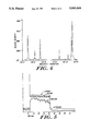
- FIG. 4 is a graphic representation of the output spectrum of one example of the pulsed light source.
- FIG. 5 is a graphic representation of voltage, current and light output waveforms associated with the pulsed light source of the present invention.
- a pulsed light source 10 in accordance with the present invention is shown in FIG. 1.
- a sealed lamp tube 12 encloses a discharge region 14 that contains a rare gas or a mixture of rare gases.
- An anode electrode 16 is sealed in one end of the lamp tube 12, and a cathode electrode 18 is sealed in the opposite end of the lamp tube 12.
- the lamp tube 12 is oriented generally vertically so that the anode electrode 16 is at the top and the cathode electrode 18 is at the bottom.
- the lamp tube contains a conductive material 20 that is a liquid at or near room temperature.
- the conductive material 20 is mercury.
- the mercury is present in sufficient quantity to form a pool at the lower end of the lamp tube 12 which covers cathode electrode 18.
- a transparent sleeve 22, having a phosphor coating 24 thereon, is positioned around lamp tube 12.
- the electrodes 16 and 18 are connected by in-leads 26 and 28, respectively, to a pulse generator 30.
- the pulse generator 30 provides pulse excitation of suitable voltage and current to energize light source 10 in a pulsed mode, as described hereinafter.
- the pulsed radiation from the lamp tube 12 is ultraviolet radiation.
- the lamp tube 12 must be an ultraviolet-transmissive material such as fused silica (quartz).
- the lamp tube 12 is formed in an elongated configuration with electrodes 16 and 18 mounted near opposite ends thereof.
- the lamp tube 12 is sealed in conventional manner by press seals 32 and 34.
- the discharge region 14 preferably has cylindrical geometry with dimensions in the range of about 3 to 12 millimeters in length by 4 millimeters inside diameter, but is not limited to these dimensions.
- wall thickness is not critical, the lamp tube 12 preferably has a wall thickness of about one millimeter.
- FIG. 2 An alternate embodiment of the lamp tube is illustrated in FIG. 2.
- the light source of FIG. 2 is generally the same as the light source 10 of FIG. 1 except for the configuration of the lamp tube.
- a lamp tube 40 has electrodes 16 and 18 mounted at opposite ends thereof.
- the lower end of lamp tube 40 is shaped to define a recess 42 surrounding cathode electrode 18.
- Recess 42 is made as small in volume as possible without interfering with lamp operation.
- the purpose of the small volume recess 42 is to insure that the cathode electrode 18 is covered with mercury in the normal operating position, while minimizing the volume of mercury within lamp tube 40. It is desirable for safety and cost reasons to minimize the volume of mercury within the lamp tube 40.
- the electrode 16 is preferably tungsten, but can also be rhenium or other similar high temperature metals. Electrode 18 can be any metal compatible with mercury. Shaping of electrodes 16 and 18 is not required.
- the spacing between electrodes 16 and 18 is in the range of about 3 millimeters to 12 millimeters, although other electrode spacings can be utilized within the scope of the present invention.
- the discharge region 14 includes a low pressure rare gas or a mixture of rare gases.
- the fill gas has a pressure in the range of about 50 torr to 200 torr. At pressures above 200 torr, emission of ultraviolet radiation is quenched.
- the fill material is argon at a pressure of about 50 torr.
- Mercury is the preferred conductive material for covering cathode electrode 18, since it is a liquid at room temperature.
- Other metals, conductive compounds and alloys that are liquid in form at or near room temperature or have a flowable or viscous characteristic at room temperature can also be utilized. Examples of such materials include indium, zinc, cesium, lithium and various amalgams.
- the selected conductive material during discharge emits ultraviolet radiation for stimulation of phosphor coating 24 and, in some cases, may emit useful visible light.
- the main purpose of the mercury or other conductive material that surrounds cathode electrode 18 is to protect cathode electrode 18 from sputtering during operation. It is known that the relatively heavy ions within the discharge region 14 bombard the cathode electrode 18 in the absence of mercury 20, due to the electric fields in the lamp tube. The pool of mercury 20 surrounding cathode electrode 18 protects the cathode electrode 18 against such sputtering. Although the mercury is sputtered by ion bombardment, it returns to its original state without damage. Furthermore, the ion bombardment causes miniature droplets of mercury to be splashed into discharge region 14 and to take part in the discharge that occurs when the lamp is pulsed. As a result, more mercury is available to participate in the discharge than would otherwise be available as a result of the normal vapor pressure of mercury within the lamp tube.
- Ultraviolet radiation from the discharge region 14 passes through lamp tube 12 and stimulates emission of visible radiation from phosphor coating 24.
- Phosphor coating 24 can be any of a variety of well-known phosphors and is selected to provide a desired color. Examples of suitable phosphors include YVO 4 :Eu (red) and YAG:Ce (yellow).
- the transparent sleeve 22 that carries phosphor coating 24 is typically glass and can have any desired configuration. The mounting details of sleeve 22 are omitted for simplicity since they are routine to those skilled in the art. For example, the sleeve 22 can be part of a transparent outer lamp envelope.
- the pulsed light source of the invention is not limited to use of a phosphor coating on the transparent sleeve 22, as shown in FIG. 1.
- An alternate phosphor configuration is illustrated in FIG. 3.
- a phosphor coating 50 is adhered to the outer surface of lamp tube 12.
- the phosphor coating 50 emits visible light upon stimulation by ultraviolet radiation from discharge region 14. Since the pulsed light source of the invention remains at or near ambient temperature during operation, the phosphor coating 50 is not exposed to elevated temperatures.
- the construction of the pulsed light source shown in FIG. 3 is otherwise the same as that shown in FIG. 1 and described hereinabove.
- the pulse generator 30 supplies pulsed electrical excitation to the light source 10, and is connected so that anode electrode 16 is pulsed to a positive potential relative to cathode electrode 18.
- the operating conditions are selected to prevent the light source 10 from reaching elevated pressures and temperatures at which operating efficiency is reduced.
- Pulse widths are preferably in the range from about 1.0 millisecond to 500 milliseconds.
- the light source can be utilized to provide a continuous series of pulses.
- the light source 10 can be utilized to provide a burst of pulses, for example, a two second burst of 5 millisecond pulses having a 50% duty cycle. The pulse burst appears as a single, two-second pulse.
- the light source 10 can be utilized to send coded signals such as Morse code or the like.
- a typical operating condition utilizes a 100 millisecond pulse at a repetition rate of once per second.
- the light source 10 requires no warmup time and has a very fast recovery after the discharge is extinguished.
- the voltage drop across the light source 10 during discharge depends on the gap between electrodes 16 and 18 and on the pressure of the gas fill.
- a typical operating voltage is about 20 volts.
- the operating current is typically in the range from about 0.2 amp to more than 2 amps.
- the pulse generator 30 is a ballast-type source that limits the current through the light source 10 at a desired operating value.
- the operating voltage is established by the characteristics of the light source 10.
- the pulse generator 30 provides means for initiating the discharge within light source 10.
- the discharge is initiated by a high voltage, short duration voltage spike on the order of 200 to 2,000 volts.
- the starting voltage spike is provided at the beginning of the energizing pulse.
- Other techniques for initiating discharges in low pressure discharge lamps are well-known to those skilled in the art. Any of a number of pulse generators that are well-known in the art can be utilized for energizing the light source 10.
- FIG. 1 An example of the pulsed light source of the present invention was constructed as shown in FIG. 1.
- the electrode 16 and the surface of mercury 20 were spaced apart by a distance of 6 millimeters, and the fill material was argon at a pressure of 50 torr.
- the phosphor coating 24 was a red phosphor, type YVO 4 :Eu.
- the quantity of mercury was sufficient to cover electrode 18.
- FIG. 4 A graphic representation of the output spectrum is shown in FIG. 4, in which relative intensity of the output is plotted as a function of wavelength in nanometers. The contribution from the emission of the phosphor is primarily limited to a narrow band around 620 nanometers. The additional emission is from the mercury and argon within the lamp tube.
- the electrical and radiative characteristics are shown in FIG. 5.
- the current, voltage and light output waveforms are plotted as a function of time.
- the current pulse has an amplitude of about 0.5 ampere.
- the voltage pulse after the initial starting spike, has an amplitude of about 20 volts.
- the light emission output in the band of interest is relatively constant during the applied pulse, and a measurable persistent emission occurs after the discharge has been extinguished.
- the persistence, or afterglow, is due to the stimulation and reradiation properties of the phosphor.
- the lamp was pulsed at a rate of four times per minute with power levels of approximately 25 watts during a 2 millisecond pulse.
- the source exceeded 800,000 pulses with no observable deterioration in the light output.
- the pulsed light source of the present invention provides numerous advantages.
- the source is operated cold without auxiliary heaters or warmup time to achieve optimum performance.
- the light source of the invention is a low pressure device, thereby avoiding the potential hazards of high pressure devices.
- the light source is very simple in construction and chemical composition.
- a wide range of pulse widths and duty cycles can be utilized for operation of the light source.
- the electrode configuration of the source, wherein the cathode is immersed in a liquid conductor such as mercury, results in a long operating life without deterioration of the electrodes.
- a wide range of colors can be obtained by utilizing different phosphors with the ultraviolet light source. It will be understood that the pulsed source can be utilized without the phosphor when a pulsed ultraviolet radiation source is required.
Landscapes
- Vessels And Coating Films For Discharge Lamps (AREA)
- Discharge Lamp (AREA)
- Discharge Lamps And Accessories Thereof (AREA)
Priority Applications (5)
| Application Number | Priority Date | Filing Date | Title |
|---|---|---|---|
| US07/212,401 US5043634A (en) | 1988-06-27 | 1988-06-27 | Pulsed light source |
| JP1161020A JPH0278148A (ja) | 1988-06-27 | 1989-06-26 | パルス化光源 |
| CA000603933A CA1316976C (en) | 1988-06-27 | 1989-06-26 | Pulsed light source |
| EP19890111706 EP0348915A3 (de) | 1988-06-27 | 1989-06-27 | Blitzlichtquelle |
| AU37076/89A AU632491B2 (en) | 1988-06-27 | 1989-06-27 | Pulsed light source |
Applications Claiming Priority (1)
| Application Number | Priority Date | Filing Date | Title |
|---|---|---|---|
| US07/212,401 US5043634A (en) | 1988-06-27 | 1988-06-27 | Pulsed light source |
Publications (1)
| Publication Number | Publication Date |
|---|---|
| US5043634A true US5043634A (en) | 1991-08-27 |
Family
ID=22790852
Family Applications (1)
| Application Number | Title | Priority Date | Filing Date |
|---|---|---|---|
| US07/212,401 Expired - Fee Related US5043634A (en) | 1988-06-27 | 1988-06-27 | Pulsed light source |
Country Status (5)
| Country | Link |
|---|---|
| US (1) | US5043634A (de) |
| EP (1) | EP0348915A3 (de) |
| JP (1) | JPH0278148A (de) |
| AU (1) | AU632491B2 (de) |
| CA (1) | CA1316976C (de) |
Cited By (33)
| Publication number | Priority date | Publication date | Assignee | Title |
|---|---|---|---|---|
| US5666031A (en) * | 1994-03-16 | 1997-09-09 | Osram Sylvania Inc. | Neon gas discharge lamp and method of pulsed operation |
| KR19980043561A (ko) * | 1996-12-04 | 1998-09-05 | 조셉 에스. 로마나우 | 네온 가스 방전 램프 및 펄스 작동 방법 |
| US5907222A (en) * | 1993-11-03 | 1999-05-25 | Litton Systems, Inc. | High efficiency backlighting system for rear illumination of electronic display devices |
| US6028694A (en) * | 1997-05-22 | 2000-02-22 | Schmidt; Gregory W. | Illumination device using pulse width modulation of a LED |
| US6157130A (en) * | 1997-05-23 | 2000-12-05 | Stanley Electric Co., Ltd. | Metal halide lamp with specific internal electrode seal detail |
| US6170320B1 (en) | 1997-01-24 | 2001-01-09 | Mainstream Engineering Corporation | Method of introducing an additive into a fluid system, especially useful for leak detection, as well as an apparatus for leak detection and a composition useful for leak detection |
| US6327897B1 (en) * | 1997-01-24 | 2001-12-11 | Mainstream Engineering Corporation | Method of introducing an in situant into a vapor compression system, especially useful for leak detection, as well as an apparatus for leak detection and a composition useful for leak detection |
| US20040101802A1 (en) * | 2002-11-21 | 2004-05-27 | Scott Robert R. | Wide bandwidth led curing light |
| US20040121281A1 (en) * | 2002-12-18 | 2004-06-24 | Fischer Dan E. | Cooling system for hand-held curing light |
| US20040169456A1 (en) * | 2001-06-19 | 2004-09-02 | Scholl Robert Peter | Low-pressure gas discharge lamp with a mercury-free gas filling |
| US20040214131A1 (en) * | 2003-04-25 | 2004-10-28 | Ultradent Products, Inc., | Spot curing lens used to spot cure a dental appliance adhesive and systems and methods employing such lenses |
| US6940659B2 (en) | 2002-01-11 | 2005-09-06 | Ultradent Products, Inc. | Cone-shaped lens having increased forward light intensity and kits incorporating such lenses |
| US6994546B2 (en) | 2002-12-18 | 2006-02-07 | Ultradent Products, Inc. | Light curing device with detachable power supply |
| US7056116B2 (en) | 2004-10-26 | 2006-06-06 | Ultradent Products, Inc. | Heat sink for dental curing light comprising a plurality of different materials |
| US7074040B2 (en) | 2004-03-30 | 2006-07-11 | Ultradent Products, Inc. | Ball lens for use with a dental curing light |
| US7106523B2 (en) | 2002-01-11 | 2006-09-12 | Ultradent Products, Inc. | Optical lens used to focus led light |
| USD530013S1 (en) | 2003-02-18 | 2006-10-10 | Ultradent Products, Inc. | Dental illumination device |
| US7144250B2 (en) | 2003-12-17 | 2006-12-05 | Ultradent Products, Inc. | Rechargeable dental curing light |
| US20070020578A1 (en) * | 2005-07-19 | 2007-01-25 | Scott Robert R | Dental curing light having a short wavelength LED and a fluorescing lens for converting wavelength light to curing wavelengths and related method |
| US7192276B2 (en) | 2003-08-20 | 2007-03-20 | Ultradent Products, Inc. | Dental curing light adapted to emit light at a desired angle |
| US7195482B2 (en) | 2003-12-30 | 2007-03-27 | Ultradent Products, Inc. | Dental curing device having a heat sink for dissipating heat |
| US20070128577A1 (en) * | 2005-12-05 | 2007-06-07 | Ultradent Products, Inc. | Dental curing lights including a capacitor power source |
| US20070231769A1 (en) * | 1998-01-20 | 2007-10-04 | Jozef Kovac | Apparatus and method for curing materials with radiation |
| US20070255266A1 (en) * | 2002-02-11 | 2007-11-01 | Cumbie William E | Method and device to inactivate and kill cells and organisms that are undesirable |
| US20080208295A1 (en) * | 2007-02-28 | 2008-08-28 | Cumbie William E | Phototherapy Treatment and Device to Improve the Appearance of Nails and skin |
| KR101174153B1 (ko) * | 2005-06-29 | 2012-08-14 | 엘지디스플레이 주식회사 | 백라이트 구동장치 및 이를 구비한 액정표시장치 |
| US8384274B2 (en) | 2004-02-12 | 2013-02-26 | Mattson Technology, Inc. | High-intensity electromagnetic radiation apparatus and methods |
| US9066777B2 (en) | 2009-04-02 | 2015-06-30 | Kerr Corporation | Curing light device |
| US9072572B2 (en) | 2009-04-02 | 2015-07-07 | Kerr Corporation | Dental light device |
| US10088175B2 (en) | 2016-07-22 | 2018-10-02 | Lg Electronics Inc. | Air conditioner |
| US10105463B2 (en) | 2016-07-22 | 2018-10-23 | Lg Electronics, Inc. | Ultraviolet (UV) sterilization module and air conditioner including UV sterilization module |
| US10220110B2 (en) | 2016-07-22 | 2019-03-05 | Lg Electronics Inc. | Ultraviolet sterilization lamp, ultraviolet sterilization module, and air conditioner including ultraviolet sterilization module |
| US10551075B2 (en) | 2016-07-22 | 2020-02-04 | Lg Electronics Inc. | Air conditioner |
Families Citing this family (4)
| Publication number | Priority date | Publication date | Assignee | Title |
|---|---|---|---|---|
| DE4325718C2 (de) * | 1993-08-02 | 1999-03-11 | Xenotest Ges Fuer Die Herstell | Beleuchtungsanordnung für Licht- und Wetterechtheitsprüfgeräte mit einer Xenon-Gas-Entladungslampe |
| RU2129319C1 (ru) * | 1997-05-19 | 1999-04-20 | Виталий Львович Будович | Уф-лампа для фотоионизационного детектора |
| DE10162147B4 (de) * | 2001-12-17 | 2007-12-06 | Optomed Optomedical Systems Gmbh | UVB-Bestrahlungsanordnung |
| JP2011014541A (ja) * | 2010-07-09 | 2011-01-20 | Mattson Technology Canada Inc | 高強度の電磁放射線発生装置及び発生方法 |
Citations (10)
| Publication number | Priority date | Publication date | Assignee | Title |
|---|---|---|---|---|
| US1042565A (en) * | 1911-08-12 | 1912-10-29 | Gen Electric | Vapor electric device. |
| US1064115A (en) * | 1910-12-13 | 1913-06-10 | Gen Electric | Vapor electric device. |
| GB763446A (en) * | 1952-09-26 | 1956-12-12 | Exxon Research Engineering Co | Improvements in or relating to a methed for photochemical reaction of organlc compounds |
| US2902618A (en) * | 1954-04-14 | 1959-09-01 | Lany Beatrice Pearson De | Cathode |
| FR2276683A1 (fr) * | 1974-06-26 | 1976-01-23 | Gould Inc | Dispositif a tube a decharge dans un gaz pour le couplage d'energies elevees |
| US4065688A (en) * | 1977-03-28 | 1977-12-27 | Westinghouse Electric Corporation | High-pressure mercury-vapor discharge lamp having a light output with incandescent characteristics |
| US4173728A (en) * | 1976-10-06 | 1979-11-06 | General Electric Company | Pulsed cesium discharge light source |
| US4245155A (en) * | 1978-12-22 | 1981-01-13 | General Electric Company | Pulsed cesium discharge light source |
| JPS5676157A (en) * | 1979-11-28 | 1981-06-23 | Ushio Inc | Mercury rare gas discharge lamp |
| GB2178230A (en) * | 1985-07-02 | 1987-02-04 | Tungsram Reszvenytarsasag | Discharge lamp with noble gas filling, especially for pulse operation |
-
1988
- 1988-06-27 US US07/212,401 patent/US5043634A/en not_active Expired - Fee Related
-
1989
- 1989-06-26 JP JP1161020A patent/JPH0278148A/ja active Pending
- 1989-06-26 CA CA000603933A patent/CA1316976C/en not_active Expired - Fee Related
- 1989-06-27 AU AU37076/89A patent/AU632491B2/en not_active Ceased
- 1989-06-27 EP EP19890111706 patent/EP0348915A3/de not_active Withdrawn
Patent Citations (10)
| Publication number | Priority date | Publication date | Assignee | Title |
|---|---|---|---|---|
| US1064115A (en) * | 1910-12-13 | 1913-06-10 | Gen Electric | Vapor electric device. |
| US1042565A (en) * | 1911-08-12 | 1912-10-29 | Gen Electric | Vapor electric device. |
| GB763446A (en) * | 1952-09-26 | 1956-12-12 | Exxon Research Engineering Co | Improvements in or relating to a methed for photochemical reaction of organlc compounds |
| US2902618A (en) * | 1954-04-14 | 1959-09-01 | Lany Beatrice Pearson De | Cathode |
| FR2276683A1 (fr) * | 1974-06-26 | 1976-01-23 | Gould Inc | Dispositif a tube a decharge dans un gaz pour le couplage d'energies elevees |
| US4173728A (en) * | 1976-10-06 | 1979-11-06 | General Electric Company | Pulsed cesium discharge light source |
| US4065688A (en) * | 1977-03-28 | 1977-12-27 | Westinghouse Electric Corporation | High-pressure mercury-vapor discharge lamp having a light output with incandescent characteristics |
| US4245155A (en) * | 1978-12-22 | 1981-01-13 | General Electric Company | Pulsed cesium discharge light source |
| JPS5676157A (en) * | 1979-11-28 | 1981-06-23 | Ushio Inc | Mercury rare gas discharge lamp |
| GB2178230A (en) * | 1985-07-02 | 1987-02-04 | Tungsram Reszvenytarsasag | Discharge lamp with noble gas filling, especially for pulse operation |
Cited By (41)
| Publication number | Priority date | Publication date | Assignee | Title |
|---|---|---|---|---|
| US5907222A (en) * | 1993-11-03 | 1999-05-25 | Litton Systems, Inc. | High efficiency backlighting system for rear illumination of electronic display devices |
| US5666031A (en) * | 1994-03-16 | 1997-09-09 | Osram Sylvania Inc. | Neon gas discharge lamp and method of pulsed operation |
| KR19980043561A (ko) * | 1996-12-04 | 1998-09-05 | 조셉 에스. 로마나우 | 네온 가스 방전 램프 및 펄스 작동 방법 |
| US6170320B1 (en) | 1997-01-24 | 2001-01-09 | Mainstream Engineering Corporation | Method of introducing an additive into a fluid system, especially useful for leak detection, as well as an apparatus for leak detection and a composition useful for leak detection |
| US6327897B1 (en) * | 1997-01-24 | 2001-12-11 | Mainstream Engineering Corporation | Method of introducing an in situant into a vapor compression system, especially useful for leak detection, as well as an apparatus for leak detection and a composition useful for leak detection |
| US20020007663A1 (en) * | 1997-01-24 | 2002-01-24 | Mainstream Engineering Corporation | Method of introducing an in situant into a vapor compression system, especially useful for leak detection, as well as an apparatus for leak detection and a composition useful for leak detection |
| US6028694A (en) * | 1997-05-22 | 2000-02-22 | Schmidt; Gregory W. | Illumination device using pulse width modulation of a LED |
| US6157130A (en) * | 1997-05-23 | 2000-12-05 | Stanley Electric Co., Ltd. | Metal halide lamp with specific internal electrode seal detail |
| US20070231769A1 (en) * | 1998-01-20 | 2007-10-04 | Jozef Kovac | Apparatus and method for curing materials with radiation |
| US9572643B2 (en) | 1998-01-20 | 2017-02-21 | Kerr Corporation | Apparatus and method for curing materials with radiation |
| US8568140B2 (en) | 1998-01-20 | 2013-10-29 | Jozef Kovac | Apparatus and method for curing materials with radiation |
| US9622839B2 (en) | 1998-01-20 | 2017-04-18 | Kerr Corporation | Apparatus and method for curing materials with radiation |
| US20040169456A1 (en) * | 2001-06-19 | 2004-09-02 | Scholl Robert Peter | Low-pressure gas discharge lamp with a mercury-free gas filling |
| US7106523B2 (en) | 2002-01-11 | 2006-09-12 | Ultradent Products, Inc. | Optical lens used to focus led light |
| US6940659B2 (en) | 2002-01-11 | 2005-09-06 | Ultradent Products, Inc. | Cone-shaped lens having increased forward light intensity and kits incorporating such lenses |
| US20070255266A1 (en) * | 2002-02-11 | 2007-11-01 | Cumbie William E | Method and device to inactivate and kill cells and organisms that are undesirable |
| US20040101802A1 (en) * | 2002-11-21 | 2004-05-27 | Scott Robert R. | Wide bandwidth led curing light |
| US6994546B2 (en) | 2002-12-18 | 2006-02-07 | Ultradent Products, Inc. | Light curing device with detachable power supply |
| US6890175B2 (en) | 2002-12-18 | 2005-05-10 | Ultradent Products, Inc. | Cooling system for hand-held curing light |
| US20040121281A1 (en) * | 2002-12-18 | 2004-06-24 | Fischer Dan E. | Cooling system for hand-held curing light |
| USD530013S1 (en) | 2003-02-18 | 2006-10-10 | Ultradent Products, Inc. | Dental illumination device |
| US20040214131A1 (en) * | 2003-04-25 | 2004-10-28 | Ultradent Products, Inc., | Spot curing lens used to spot cure a dental appliance adhesive and systems and methods employing such lenses |
| US7192276B2 (en) | 2003-08-20 | 2007-03-20 | Ultradent Products, Inc. | Dental curing light adapted to emit light at a desired angle |
| US7144250B2 (en) | 2003-12-17 | 2006-12-05 | Ultradent Products, Inc. | Rechargeable dental curing light |
| US7195482B2 (en) | 2003-12-30 | 2007-03-27 | Ultradent Products, Inc. | Dental curing device having a heat sink for dissipating heat |
| US8384274B2 (en) | 2004-02-12 | 2013-02-26 | Mattson Technology, Inc. | High-intensity electromagnetic radiation apparatus and methods |
| US7074040B2 (en) | 2004-03-30 | 2006-07-11 | Ultradent Products, Inc. | Ball lens for use with a dental curing light |
| US7056116B2 (en) | 2004-10-26 | 2006-06-06 | Ultradent Products, Inc. | Heat sink for dental curing light comprising a plurality of different materials |
| KR101174153B1 (ko) * | 2005-06-29 | 2012-08-14 | 엘지디스플레이 주식회사 | 백라이트 구동장치 및 이를 구비한 액정표시장치 |
| US20070020578A1 (en) * | 2005-07-19 | 2007-01-25 | Scott Robert R | Dental curing light having a short wavelength LED and a fluorescing lens for converting wavelength light to curing wavelengths and related method |
| US20070128577A1 (en) * | 2005-12-05 | 2007-06-07 | Ultradent Products, Inc. | Dental curing lights including a capacitor power source |
| US20080208295A1 (en) * | 2007-02-28 | 2008-08-28 | Cumbie William E | Phototherapy Treatment and Device to Improve the Appearance of Nails and skin |
| US9066777B2 (en) | 2009-04-02 | 2015-06-30 | Kerr Corporation | Curing light device |
| US9072572B2 (en) | 2009-04-02 | 2015-07-07 | Kerr Corporation | Dental light device |
| US9693846B2 (en) | 2009-04-02 | 2017-07-04 | Kerr Corporation | Dental light device |
| US9730778B2 (en) | 2009-04-02 | 2017-08-15 | Kerr Corporation | Curing light device |
| US9987110B2 (en) | 2009-04-02 | 2018-06-05 | Kerr Corporation | Dental light device |
| US10088175B2 (en) | 2016-07-22 | 2018-10-02 | Lg Electronics Inc. | Air conditioner |
| US10105463B2 (en) | 2016-07-22 | 2018-10-23 | Lg Electronics, Inc. | Ultraviolet (UV) sterilization module and air conditioner including UV sterilization module |
| US10220110B2 (en) | 2016-07-22 | 2019-03-05 | Lg Electronics Inc. | Ultraviolet sterilization lamp, ultraviolet sterilization module, and air conditioner including ultraviolet sterilization module |
| US10551075B2 (en) | 2016-07-22 | 2020-02-04 | Lg Electronics Inc. | Air conditioner |
Also Published As
| Publication number | Publication date |
|---|---|
| AU3707689A (en) | 1990-01-04 |
| JPH0278148A (ja) | 1990-03-19 |
| EP0348915A3 (de) | 1991-03-27 |
| CA1316976C (en) | 1993-04-27 |
| AU632491B2 (en) | 1993-01-07 |
| EP0348915A2 (de) | 1990-01-03 |
Similar Documents
| Publication | Publication Date | Title |
|---|---|---|
| US5043634A (en) | Pulsed light source | |
| KR100299151B1 (ko) | 비간섭성방출방사원의동작방법 | |
| US3319119A (en) | Metal vapor spectral lamp with mercury and a metal halide at subatmospheric pressure | |
| US8946993B2 (en) | Fluorescent excimer lamps | |
| KR100292020B1 (ko) | 방전램프 | |
| US2924733A (en) | Wall-stabilized electric high-pressure gaseous discharge lamp | |
| EP0320974B1 (de) | Pulsierend betriebene Entladungslampe mit auswählbarer Farbe | |
| KR20020064180A (ko) | 고압 방전등 및 그 시동방법 | |
| US4874988A (en) | Pulsed metal halide arc discharge light source | |
| EP0183247A2 (de) | Hochdruckmetallhalogenidbogenlampe mit Xenonpuffergas | |
| KR20100002115A (ko) | 고강도 방전 램프용 점등 보조기 | |
| US3893768A (en) | Zeeman modulated spectral source | |
| US3516012A (en) | Argon laser | |
| US4356428A (en) | Lighting system | |
| KR880001873B1 (ko) | 세그멘트 표시 시스템 | |
| US2020723A (en) | Electric gaseous discharge device | |
| WO1987003422A1 (en) | Hollow cathode assembly and lamp | |
| JPH0378735B2 (de) | ||
| US2010852A (en) | Gaseous electric discharge device | |
| US3989972A (en) | High pressure mercury vapor discharge lamp containing bismuth iodide | |
| CA1308159C (en) | High pressure sodium discharge tube support structure | |
| JP3253163B2 (ja) | 放電ランプ | |
| CA1316975C (en) | Pulsed metal halide salt source | |
| SU900349A1 (ru) | Электрод дл газоразр дной лампы | |
| US3721916A (en) | Cold cathode construction for gaseous laser |
Legal Events
| Date | Code | Title | Description |
|---|---|---|---|
| AS | Assignment |
Owner name: GTE PRODUCTS CORPORATION, A DE CORP. Free format text: ASSIGNMENT OF ASSIGNORS INTEREST.;ASSIGNORS:ROTHWELL, HAROLD L. JR.;ENGLISH, GEORGE J.;REEL/FRAME:004935/0480 Effective date: 19880627 |
|
| AS | Assignment |
Owner name: GTE PRODUCTS CORPORATION, A DE CORP. Free format text: ASSIGNMENT OF ASSIGNORS INTEREST.;ASSIGNOR:VAN PEENEN, PETER J.;REEL/FRAME:005025/0274 Effective date: 19890206 |
|
| FEPP | Fee payment procedure |
Free format text: PAYOR NUMBER ASSIGNED (ORIGINAL EVENT CODE: ASPN); ENTITY STATUS OF PATENT OWNER: LARGE ENTITY |
|
| FPAY | Fee payment |
Year of fee payment: 4 |
|
| REMI | Maintenance fee reminder mailed | ||
| LAPS | Lapse for failure to pay maintenance fees | ||
| FP | Lapsed due to failure to pay maintenance fee |
Effective date: 19990827 |
|
| STCH | Information on status: patent discontinuation |
Free format text: PATENT EXPIRED DUE TO NONPAYMENT OF MAINTENANCE FEES UNDER 37 CFR 1.362 |