US5022284A - Automatic transmission control system - Google Patents
Automatic transmission control system Download PDFInfo
- Publication number
- US5022284A US5022284A US07/587,790 US58779090A US5022284A US 5022284 A US5022284 A US 5022284A US 58779090 A US58779090 A US 58779090A US 5022284 A US5022284 A US 5022284A
- Authority
- US
- United States
- Prior art keywords
- shift
- pressure
- oil
- valve
- oil temperature
- Prior art date
- Legal status (The legal status is an assumption and is not a legal conclusion. Google has not performed a legal analysis and makes no representation as to the accuracy of the status listed.)
- Expired - Lifetime
Links
Images


Classifications
-
- F—MECHANICAL ENGINEERING; LIGHTING; HEATING; WEAPONS; BLASTING
- F16—ENGINEERING ELEMENTS AND UNITS; GENERAL MEASURES FOR PRODUCING AND MAINTAINING EFFECTIVE FUNCTIONING OF MACHINES OR INSTALLATIONS; THERMAL INSULATION IN GENERAL
- F16H—GEARING
- F16H61/00—Control functions within control units of change-speed- or reversing-gearings for conveying rotary motion ; Control of exclusively fluid gearing, friction gearing, gearings with endless flexible members or other particular types of gearing
- F16H61/04—Smoothing ratio shift
- F16H61/06—Smoothing ratio shift by controlling rate of change of fluid pressure
- F16H61/065—Smoothing ratio shift by controlling rate of change of fluid pressure using fluid control means
- F16H61/067—Smoothing ratio shift by controlling rate of change of fluid pressure using fluid control means using an accumulator
-
- F—MECHANICAL ENGINEERING; LIGHTING; HEATING; WEAPONS; BLASTING
- F16—ENGINEERING ELEMENTS AND UNITS; GENERAL MEASURES FOR PRODUCING AND MAINTAINING EFFECTIVE FUNCTIONING OF MACHINES OR INSTALLATIONS; THERMAL INSULATION IN GENERAL
- F16H—GEARING
- F16H59/00—Control inputs to control units of change-speed-, or reversing-gearings for conveying rotary motion
- F16H59/68—Inputs being a function of gearing status
- F16H59/72—Inputs being a function of gearing status dependent on oil characteristics, e.g. temperature, viscosity
-
- F—MECHANICAL ENGINEERING; LIGHTING; HEATING; WEAPONS; BLASTING
- F16—ENGINEERING ELEMENTS AND UNITS; GENERAL MEASURES FOR PRODUCING AND MAINTAINING EFFECTIVE FUNCTIONING OF MACHINES OR INSTALLATIONS; THERMAL INSULATION IN GENERAL
- F16H—GEARING
- F16H61/00—Control functions within control units of change-speed- or reversing-gearings for conveying rotary motion ; Control of exclusively fluid gearing, friction gearing, gearings with endless flexible members or other particular types of gearing
- F16H61/04—Smoothing ratio shift
- F16H61/08—Timing control
Definitions
- the invention relates to an automatic transmission control device in which gears of the transmission are shifted or changed by a plurality of friction engaging elements.
- Shift control systems of an automatic transmission are operated, on the one hand, by a combination of one-way clutches, multiple friction engaging elements (clutches, brakes) and band brakes and, the other hand, by a combination of multiple friction engaging elements (clutches, brakes).
- the shift control system includes a timing control for timing the intake and exhaust of the hydraulic operating oil supply from an operating means of a friction engaging element.
- the timing control can operate to exhaust the hydraulic operating oil when the oil pressure on the intake side of the operator of the friction element reaches a predetermined pressure value.
- This type of a timing control is operated by, for example, a shift timing valve shown in a manual for the Toyota Landcruiser New Automobile, lines 10-36, and FIG. 6 (published in 1984).
- the timing valve therein is a 2 ⁇ 3 shift timing valve which controls timing for draining the oil pressure of the brake B1 when the system is shifted from the 2nd gear to the 3rd gear so as to disengage the brake B1 and engage the clutch C3.
- the timing valve reduces the shift-shock which occurs during the shift between gear ratios.
- a spool 1 is urged to the upper position by the spring 2 while the vehicle is operated in the second gear.
- the engaging oil pressure P c2 of the rear clutch C 2 is transmitted through an orifice (not shown) from the 2 ⁇ 3 shift valve via passage L 1 .
- the spool 1 is then urged to the lower position against the oil pressure P ACC transmitted from the accumulator control valve through the passage L 2 and against the force of the spring 2.
- the oil pressure P B1 of the brake B1 transmitted through the passage L 3 only passes through the passage L 4 and the orifice 3. Therefore, the engagement of the second brake B1 is maintained.
- the engaging oil pressure PC 2 of the clutch C 2 increases further and the spool 1 moves further to a lower position, the passage L 5 provided below the orifice 3 is opened and the oil pressure P B1 is quickly reduced and the engagement of the brake B1 is released.
- the oil pressure of the rear clutch C2 is changed to a pressure, the range of which overlaps slightly with the pressure range of the second brake B1, and the rear clutch C 2 is engaged. Thereby, the shifting to the third gear ratio is completed.
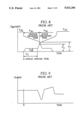
- FIG. 8 shows a characteristic of the C 2 clutch oil pressure Pc2 and the B 1 brake oil pressure P B1 at the 2 ⁇ 3 shift by the 2 ⁇ 3 shift timing valve of FIG. 7.
- FIG. 9 shows the characteristic of the output shaft torque which causes the shift shock in this shifting operation.
- the Japanese Patent Publication No. 4940585 also shows the above mentioned structure.
- the shift shock depends on the predetermined pressure value (P A in FIG. 8) to change the shift timing value for quick drain of the engaging oil pressure of the disengaging side of the multiple element friction engaging device. The lower the shift shock the better for the automobile.
- An oil circuit has a resistance to the passage of the oil flow, therefore there is a pressure difference P between the clutch oil pressure P B in the chamber of the clutch C 2 and the piston stroke oil pressure PB supplied to the 2 ⁇ 3 shift timing valve (shown in FIG. 10) and, the lower the oil temperature is, the larger the pressure difference P.
- the oil pressure P A at the changing point of the shift timing valve is a predetermined higher value than the piston stroke oil pressure P B of the multiple engaging element of the engaging side of the engaging device.
- the oil pressure P A is higher than the oil pressure P B at a low oil temperature.
- the viscosity of the oil decreases with the increase of the oil temperature
- the resistance of the oil in the oil circuit passages reduces and the pressure difference between the oil pressure P A and the oil pressure P B at the low oil temperature and the oil pressure P B at the high oil temperature increases, therefore the shift shock in the normal driving mode becomes worse.
- an automatic transmission control device is provided with a first multiple element friction engaging device, a second multiple element friction engaging device engaged for the purpose of the up-shift when the first multiple element friction engaging device is released, a shift timing valve having a return spring and a movable part so that an engaging oil pressure of the first multiple element friction engaging device is reduced quickly when the force transmitted by an engaging oil pressure of the second multiple element friction engaging device supplied to the timing valve is larger than the force transmitted by an accumulator back pressure modulated by the return spring and a throttle pressure from a throttle valve.
- a throttle valve operating means controls the throttle valve to modulate the throttle pressure
- an oil temperature sensing means is disposed in an oil control circuit of the transmission control device
- a control means operates the throttle valve operating means so that the accumulator back pressure modulated by the throttle pressure is less than that provided when the oil temperature is under a predetermined value as compared to when the oil temperature sensed by the oil temperature sensing means is greater than the predetermined value.
- FIG. 1 shows a schematic of a gear train of an automatic transmission of the invention
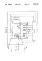
- FIG. 2 shows an embodiment of an oil pressure control circuit of the invention
- FIG. 3 shows a control system used in the embodiment of the FIG. 2,
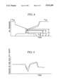
- FIG. 4 shows an oil pressure characteristic of the invention
- FIG. 5 shows a torque characteristic of an output shaft of the invention
- FIG. 6 is a flow chart showing control operations of the invention.
- FIG. 7 shows a sectional view of a shift timing valve of the prior art
- FIG. 8 shows an oil pressure characteristic of the shift timing valve according to FIG. 7;
- FIG. 9 shows a torque characteristic of the output shaft of the prior art
- FIG. 10 shows an oil pressure characteristic between the clutch chamber of the engaging side and the shift timing valve.
- number 11 indicates a manual valve
- 12 indicates a 2 ⁇ 3 shift timing valve
- 13 indicates a 1 ⁇ 2 shift valve
- 14 indicates a 2 ⁇ 3 shift valve
- 15 indicates a 3 ⁇ 4 shift valve
- 16 indicates a throttle valve
- 17 indicates a solenoid controlling throttle oil pressure
- 18 indicates a brake B 1 accumulator
- 19 indicates an accumulator control valve
- 20 indicates a primary regulator valve
- 21 indicates a secondary regulator valve
- 22 indicates a lock-up control valve. Shifting is effected by a shift control of solenoid valves SOL1 and SOL2 and on-off operations of the multiple element friction engaging devices for each gear ratio are shown in the following table 1.
- a reference number 23 indicates an engine
- 24 indicates a automatic transmission
- S1 indicates an engine rotational speed sensor
- S2 indicates a throttle sensor
- S3 indicates a C 1 clutch drum rotational speed sensor
- S4 indicates an output shaft rotational speed sensor
- S5 indicates a position sensor
- S6 indicates an oil temperature sensor disposed in a passage of the oil pressure control circuit between an oil strainer and an oil cooler.
- Signals from the sensors are transmitted to a microcomputer 25.
- a first solenoid valve SOL1, a second solenoid valve SOL2, a solenoid to control the throttle oil pressure 17, a timing solenoid valve SOL3, and a solenoid valve to control the lock-up SOL 4 are operated by signals from the microcomputer 25.
- the spool 12A of the 2 ⁇ 3 shift timing valve 12 is located in the lower position (in the left valve condition in FIG. 2) by means of the return spring 12B and the accumulator back pressure supplied from the accumulator control valve 19 to the port 12b through the passage L13. Therefore, the B 1 oil pressure supplied to the port 12a is reduced by draining the oil through the orifice 12c, and the oil pressure for actuating the brake B 1 slowly decreases.
- the 2 ⁇ 3 shift valve 14 is changed by the 2 ⁇ 3 shift-up, the port 14d is communicated with the port 14e, and the line pressure is supplied to the clutch C 2 through the passages L14 and L15.
- the line pressure (C 2 oil pressure) supplied to the clutch C 2 is supplied to the port 12d of the 2 ⁇ 3 shift timing valve 12 through the passage L16, and acts in the opposite direction to the return spring 12B and the accumulator back pressure P ACC from the port 12c against the spool 12A.
- the 2 ⁇ 3 shift timing valve 12 is changed. Namely the oil pressure P A is determined by the accumulator back pressure P ACC .
- FIGS. 4 and 5 show an oil pressure characteristic of the B 1 oil pressure (P B1 ) and the C 2 oil pressure (P c2 ) at the 2 ⁇ 3 shift-up and a torque characteristic of the output shaft, the full lines in FIGS. 4 and 5 are suitable for the oil pressure characteristics shown in FIGS. 8 and 9.
- the microcomputer 25 receives the signals form the sensors S 1 , S 2 , S 4 , senses the beginning of the 2 ⁇ 3 shifting (a), and senses the oil temperature through the oil temperature sensor S6(b) further decides whether the oil temperature is over the predetermined value (c). If the temperature is under the value ("NO" in FIG.
- the second solenoid valve SOL2 is changed to "OFF" and the 2 ⁇ 3 shift valve 14 is changed (d).
- the duty coefficient of the solenoid to control the throttle oil pressure is decided at (e), and the duty coefficient is maintained to a predetermined value ⁇ 1 until the end (g) of shift changing stops(f).
- the throttle pressure is provided by the throttle valve 16 according to the duty coefficient ⁇ 1 , and the accumulator back pressure P ACC is provided by the accumulator control valve 19 to the 2 ⁇ 3 shift timing value 12 through the passage L13 according to the throttle pressure. Therefore, if the oil temperature is under the predetermined value, the changing oil pressure P A at the low temperature is decided by the formula (1) (FIG. 4). If the oil temperature is over the predetermined value ("YES" in FIG.
- the second solenoid valve SOL2 is changed to "OFF" to change the 2 ⁇ 3 shift valve 14 (h)
- the duty coefficient of the solenoid 17 to control the throttle oil pressure is decided (i)
- the value ⁇ 1 is changed to ⁇ 2 (j).
- the throttle pressure is provided by the throttle value 16 according to the duty coefficient ⁇ 2
- the accumulator back pressure P ACC ' (P ACC >P ACC ') is provided by the accumulator control valve 19 to the 2 ⁇ 3 shift timing valve 12 through the passage L13 according to the throttle pressure. Therefore, if the oil temperature is over the predetermined value, the changing oil pressure P A ' (P A ⁇ P A ' in FIG. 4) at the high temperature is decided by the formula (1).
- the duly coefficient ⁇ 2 is changed to ⁇ 1 (1) and the shifting is accomplished.
- the oil temperature is over the predetermined value
- the oil pressure characteristics of the C 2 clutch oil pressure and B 1 brake oil pressure are shown as a dotted line in FIG. 4 and the torque characteristic of the output shaft is shown as a dotted line in FIG. 5.
- the change of the dotted line is smaller than one of the full line, therefore, the shift shock is reduced.
- the oil pressure P A at the changing point is 1.4 Kg/cm 2 when the oil temperature is less than 80° C. and a P A value of 1.7 Kg/cm 2 at temperatures over 80° C. is best for a reduction in shift shock.
- the invention is used not only for the 2 ⁇ 3 shift timing valve but also for the other shift timing valves (ex. 1 ⁇ 2 shift timing valve, 3 ⁇ 4 shift timing valve).
Landscapes
- Engineering & Computer Science (AREA)
- General Engineering & Computer Science (AREA)
- Physics & Mathematics (AREA)
- Fluid Mechanics (AREA)
- Mechanical Engineering (AREA)
- Control Of Transmission Device (AREA)
Applications Claiming Priority (2)
| Application Number | Priority Date | Filing Date | Title |
|---|---|---|---|
| JP01-253749 | 1989-09-30 | ||
| JP1253749A JP2830173B2 (ja) | 1989-09-30 | 1989-09-30 | 自動変速機の変速制御装置 |
Publications (1)
| Publication Number | Publication Date |
|---|---|
| US5022284A true US5022284A (en) | 1991-06-11 |
Family
ID=17255608
Family Applications (1)
| Application Number | Title | Priority Date | Filing Date |
|---|---|---|---|
| US07/587,790 Expired - Lifetime US5022284A (en) | 1989-09-30 | 1990-09-25 | Automatic transmission control system |
Country Status (2)
| Country | Link |
|---|---|
| US (1) | US5022284A (ja) |
| JP (1) | JP2830173B2 (ja) |
Cited By (5)
| Publication number | Priority date | Publication date | Assignee | Title |
|---|---|---|---|---|
| US5101686A (en) * | 1989-11-15 | 1992-04-07 | Mazda Motor Corporation | Automatic transmission capable of executing cutback control |
| US5133231A (en) * | 1990-04-11 | 1992-07-28 | Aisin Seiki Kabushiki Kaisha | Hydraulic control system for automatic transmission |
| US5144866A (en) * | 1988-08-11 | 1992-09-08 | Nissan Motor Co., Ltd. | Shift control system for automatic transmission |
| US5261295A (en) * | 1989-10-11 | 1993-11-16 | Nissan Motor Co., Ltd. | Temperature responsive line pressure control arrangement for automotive automatic transmission |
| US5305663A (en) * | 1992-08-10 | 1994-04-26 | Ford Motor Company | Automatic transmission control system |
Families Citing this family (1)
| Publication number | Priority date | Publication date | Assignee | Title |
|---|---|---|---|---|
| JP5136534B2 (ja) * | 2008-09-30 | 2013-02-06 | アイシン・エィ・ダブリュ株式会社 | 自動変速機の制御装置 |
Citations (5)
| Publication number | Priority date | Publication date | Assignee | Title |
|---|---|---|---|---|
| US4637281A (en) * | 1985-07-19 | 1987-01-20 | Ford Motor Company | Control valve system for a four-speed automatic power transmission transaxle |
| US4779489A (en) * | 1986-06-27 | 1988-10-25 | Borg-Warner Automotive, Inc. | Control system for controlling transmission fluid pressure |
| US4854195A (en) * | 1984-07-31 | 1989-08-08 | Aisin-Warner Limited | Hydraulic control system for vehicular automatic transmission with two accumulator control values to vary back pressure to accumulator to follow the change in engine torque |
| US4856381A (en) * | 1987-04-17 | 1989-08-15 | Toyota Jidosha Kabushiki Kaisha | Fluid pressure control system for automatic transmission |
| US4930376A (en) * | 1988-09-01 | 1990-06-05 | Ford Motor Company | Minimizing delay in low temperature engagement of automatic transmission clutch or brake |
-
1989
- 1989-09-30 JP JP1253749A patent/JP2830173B2/ja not_active Expired - Fee Related
-
1990
- 1990-09-25 US US07/587,790 patent/US5022284A/en not_active Expired - Lifetime
Patent Citations (5)
| Publication number | Priority date | Publication date | Assignee | Title |
|---|---|---|---|---|
| US4854195A (en) * | 1984-07-31 | 1989-08-08 | Aisin-Warner Limited | Hydraulic control system for vehicular automatic transmission with two accumulator control values to vary back pressure to accumulator to follow the change in engine torque |
| US4637281A (en) * | 1985-07-19 | 1987-01-20 | Ford Motor Company | Control valve system for a four-speed automatic power transmission transaxle |
| US4779489A (en) * | 1986-06-27 | 1988-10-25 | Borg-Warner Automotive, Inc. | Control system for controlling transmission fluid pressure |
| US4856381A (en) * | 1987-04-17 | 1989-08-15 | Toyota Jidosha Kabushiki Kaisha | Fluid pressure control system for automatic transmission |
| US4930376A (en) * | 1988-09-01 | 1990-06-05 | Ford Motor Company | Minimizing delay in low temperature engagement of automatic transmission clutch or brake |
Cited By (6)
| Publication number | Priority date | Publication date | Assignee | Title |
|---|---|---|---|---|
| US5144866A (en) * | 1988-08-11 | 1992-09-08 | Nissan Motor Co., Ltd. | Shift control system for automatic transmission |
| US5261295A (en) * | 1989-10-11 | 1993-11-16 | Nissan Motor Co., Ltd. | Temperature responsive line pressure control arrangement for automotive automatic transmission |
| US5101686A (en) * | 1989-11-15 | 1992-04-07 | Mazda Motor Corporation | Automatic transmission capable of executing cutback control |
| US5133231A (en) * | 1990-04-11 | 1992-07-28 | Aisin Seiki Kabushiki Kaisha | Hydraulic control system for automatic transmission |
| US5305663A (en) * | 1992-08-10 | 1994-04-26 | Ford Motor Company | Automatic transmission control system |
| US5413539A (en) * | 1992-08-10 | 1995-05-09 | Ford Motor Company | Control system for controlling engagement of an automatic transmission torque converter clutch |
Also Published As
| Publication number | Publication date |
|---|---|
| JP2830173B2 (ja) | 1998-12-02 |
| JPH03117767A (ja) | 1991-05-20 |
Similar Documents
| Publication | Publication Date | Title |
|---|---|---|
| US5910068A (en) | Countershaft automatic gearbox, in particular an automatic gearbox for motor vehicles | |
| US4637281A (en) | Control valve system for a four-speed automatic power transmission transaxle | |
| US4982622A (en) | Hydraulic pressure control device for automatic transmission | |
| US4506563A (en) | Hydraulic control system for automatic transmission gear | |
| US5345843A (en) | Speed change control apparatus and method for an automotive automatic transmission | |
| US4616531A (en) | Hydraulic and electronic control system for an automatic transmission | |
| EP0366003B1 (en) | Line pressure control system for automatic transmission | |
| EP0310117A1 (en) | Lock-up control system for automatic transmission | |
| US5086668A (en) | Line pressure control system for automatic transmission | |
| US4219109A (en) | Oil pressure control means for an automatic transmission | |
| CA1168129A (en) | Hydraulic control for a power transmission | |
| JPH01295060A (ja) | 自動変速機の変速制御装置 | |
| US5421791A (en) | Shift control arrangement for automatic transmission | |
| US5079973A (en) | Hydraulic speed change stage control system | |
| GB2077373A (en) | Shift Control Mechanism in an Automatic Transmission for Vehicles | |
| US5486146A (en) | Hydraulic control circuit for automatic transmission | |
| US5109733A (en) | Hydraulic control device for an automatic transmission | |
| US5022284A (en) | Automatic transmission control system | |
| US5409421A (en) | Control apparatus for hydraulically operated vehicular transmission | |
| US5431608A (en) | Method and device for controlling clutch of automotive automatic transmission | |
| US5888171A (en) | Hydraulic pressure as a function of friction coefficient in control system for automatic transmission | |
| US5213013A (en) | Line pressure control system for automatic transmission | |
| US5707318A (en) | Automatic transmission control device | |
| US5429561A (en) | Shift control system with engagement pressure as a function of torque input and the type of shifts | |
| JP3478438B2 (ja) | 自動変速機の油圧制御装置 |
Legal Events
| Date | Code | Title | Description |
|---|---|---|---|
| AS | Assignment |
Owner name: AISIN SEIKI KABUSHIKI KAISHA, JAPAN Free format text: ASSIGNMENT OF ASSIGNORS INTEREST.;ASSIGNOR:SHIMEI, MASATO;REEL/FRAME:005455/0763 Effective date: 19900925 |
|
| STCF | Information on status: patent grant |
Free format text: PATENTED CASE |
|
| FEPP | Fee payment procedure |
Free format text: PAYOR NUMBER ASSIGNED (ORIGINAL EVENT CODE: ASPN); ENTITY STATUS OF PATENT OWNER: LARGE ENTITY |
|
| FPAY | Fee payment |
Year of fee payment: 4 |
|
| FPAY | Fee payment |
Year of fee payment: 8 |
|
| FPAY | Fee payment |
Year of fee payment: 12 |