EP0366003B1 - Line pressure control system for automatic transmission - Google Patents
Line pressure control system for automatic transmission Download PDFInfo
- Publication number
- EP0366003B1 EP0366003B1 EP89119407A EP89119407A EP0366003B1 EP 0366003 B1 EP0366003 B1 EP 0366003B1 EP 89119407 A EP89119407 A EP 89119407A EP 89119407 A EP89119407 A EP 89119407A EP 0366003 B1 EP0366003 B1 EP 0366003B1
- Authority
- EP
- European Patent Office
- Prior art keywords
- line pressure
- shift operation
- control system
- speed
- shift
- Prior art date
- Legal status (The legal status is an assumption and is not a legal conclusion. Google has not performed a legal analysis and makes no representation as to the accuracy of the status listed.)
- Expired - Lifetime
Links
Images


Classifications
-
- F—MECHANICAL ENGINEERING; LIGHTING; HEATING; WEAPONS; BLASTING
- F16—ENGINEERING ELEMENTS AND UNITS; GENERAL MEASURES FOR PRODUCING AND MAINTAINING EFFECTIVE FUNCTIONING OF MACHINES OR INSTALLATIONS; THERMAL INSULATION IN GENERAL
- F16H—GEARING
- F16H61/00—Control functions within control units of change-speed- or reversing-gearings for conveying rotary motion ; Control of exclusively fluid gearing, friction gearing, gearings with endless flexible members or other particular types of gearing
- F16H61/0021—Generation or control of line pressure
-
- F—MECHANICAL ENGINEERING; LIGHTING; HEATING; WEAPONS; BLASTING
- F16—ENGINEERING ELEMENTS AND UNITS; GENERAL MEASURES FOR PRODUCING AND MAINTAINING EFFECTIVE FUNCTIONING OF MACHINES OR INSTALLATIONS; THERMAL INSULATION IN GENERAL
- F16H—GEARING
- F16H61/00—Control functions within control units of change-speed- or reversing-gearings for conveying rotary motion ; Control of exclusively fluid gearing, friction gearing, gearings with endless flexible members or other particular types of gearing
- F16H61/04—Smoothing ratio shift
- F16H61/06—Smoothing ratio shift by controlling rate of change of fluid pressure
- F16H61/061—Smoothing ratio shift by controlling rate of change of fluid pressure using electric control means
-
- F—MECHANICAL ENGINEERING; LIGHTING; HEATING; WEAPONS; BLASTING
- F16—ENGINEERING ELEMENTS AND UNITS; GENERAL MEASURES FOR PRODUCING AND MAINTAINING EFFECTIVE FUNCTIONING OF MACHINES OR INSTALLATIONS; THERMAL INSULATION IN GENERAL
- F16H—GEARING
- F16H61/00—Control functions within control units of change-speed- or reversing-gearings for conveying rotary motion ; Control of exclusively fluid gearing, friction gearing, gearings with endless flexible members or other particular types of gearing
- F16H2061/0075—Control functions within control units of change-speed- or reversing-gearings for conveying rotary motion ; Control of exclusively fluid gearing, friction gearing, gearings with endless flexible members or other particular types of gearing characterised by a particular control method
- F16H2061/0087—Adaptive control, e.g. the control parameters adapted by learning
-
- F—MECHANICAL ENGINEERING; LIGHTING; HEATING; WEAPONS; BLASTING
- F16—ENGINEERING ELEMENTS AND UNITS; GENERAL MEASURES FOR PRODUCING AND MAINTAINING EFFECTIVE FUNCTIONING OF MACHINES OR INSTALLATIONS; THERMAL INSULATION IN GENERAL
- F16H—GEARING
- F16H61/00—Control functions within control units of change-speed- or reversing-gearings for conveying rotary motion ; Control of exclusively fluid gearing, friction gearing, gearings with endless flexible members or other particular types of gearing
- F16H61/02—Control functions within control units of change-speed- or reversing-gearings for conveying rotary motion ; Control of exclusively fluid gearing, friction gearing, gearings with endless flexible members or other particular types of gearing characterised by the signals used
- F16H61/0202—Control functions within control units of change-speed- or reversing-gearings for conveying rotary motion ; Control of exclusively fluid gearing, friction gearing, gearings with endless flexible members or other particular types of gearing characterised by the signals used the signals being electric
- F16H61/0251—Elements specially adapted for electric control units, e.g. valves for converting electrical signals to fluid signals
- F16H2061/0255—Solenoid valve using PWM or duty-cycle control
-
- F—MECHANICAL ENGINEERING; LIGHTING; HEATING; WEAPONS; BLASTING
- F16—ENGINEERING ELEMENTS AND UNITS; GENERAL MEASURES FOR PRODUCING AND MAINTAINING EFFECTIVE FUNCTIONING OF MACHINES OR INSTALLATIONS; THERMAL INSULATION IN GENERAL
- F16H—GEARING
- F16H59/00—Control inputs to control units of change-speed-, or reversing-gearings for conveying rotary motion
- F16H59/68—Inputs being a function of gearing status
- F16H59/72—Inputs being a function of gearing status dependent on oil characteristics, e.g. temperature, viscosity
-
- F—MECHANICAL ENGINEERING; LIGHTING; HEATING; WEAPONS; BLASTING
- F16—ENGINEERING ELEMENTS AND UNITS; GENERAL MEASURES FOR PRODUCING AND MAINTAINING EFFECTIVE FUNCTIONING OF MACHINES OR INSTALLATIONS; THERMAL INSULATION IN GENERAL
- F16H—GEARING
- F16H61/00—Control functions within control units of change-speed- or reversing-gearings for conveying rotary motion ; Control of exclusively fluid gearing, friction gearing, gearings with endless flexible members or other particular types of gearing
- F16H61/04—Smoothing ratio shift
- F16H61/08—Timing control
Definitions
- the present invention relates to a control system for an automatic transmission of motor vehicle, more specifically to a line pressure control for a hydraulic control mechanism of the transmission.
- an automatic transmission of a motor vehicle is provided with a torque converter, a transmitting mechanism employing a planetary gear mechanism.
- the transmission is also provided with a plurality of frictional elements such as clutches, brakes for establishing a desirable shift gear stage among the plurality of shift gear stages provided in the transmission.
- a hydraulic control circuit is provided with a plurality of solenoid valves for switching hydraulic passages in the circuit so that the frictional elements are engaged and disengaged to perform a desirable shift operation.
- Japanese Patent publication No. 54-2349 issued to Ford Motor corporation and published for opposition on February 6, 1979 discloses a basic electrical hydraulic control system for an automatic transmission in which regulator valves are provided for controlling a line pressure of hydraulic passages of circuit of the transmission, and pilot pressures of the regulator valves are controlled by solenoid valves.
- the frequency of control signal for the solenoid valves is determined taking account of reliability of operation, durability thereof and the like. It should be noted that as the frequency of the control signal is decreased, the response in the line pressure control is deteriorated but that if the frequency is too high, the durability and the reliability of the solenoid is badly affected.
- a known control system for controlling the transmission fluid pressure controls the pressure of a transmission fluid in order to hydraulically actuate appropriate elements to change the ratio between a driving input shaft and a driven output shaft.
- Pressurized transmission fluid is supplied to a solenoid valve which is operated by a pulse width modulated signal.
- the duty cycle of the pulse width modulated signal is adjusted to produce an appropriate transmission fluid pressure to perfom several functions as actuating a clutch, shifting gears.
- the known control system is further provided with temperature sensing means for sensing the temperature of the transmission fluid. Further, means are provided, responsive to the temperature sensing means for adjusting the characteristic of the electrical signal as a function of the temperature of the transmission fluid, that is by changing the frequency of the pulse width modulated signal.
- this known control system is particularly useful in maintaining a proper pressure control under cold weather conditions when the transmission fluid thickens and its viscosity increases. If the temperature of the transmission fluid is high, the pulse width modulated signal will be set to a high frequency, thereby achieving a fast response time. If the temperature is low, the frequency will be decreased preventing an insufficient fluid flow but still providing a satisfactory operation.
- the frequency control device may be provided in a control section in the solenoid valve.
- the control signal may be a duty signal of a certain duty ratio determined by a control unit as constituted by a microcomputer.
- the frequency of the control signal for the solenoid valve is maintained at a proper value in view of the durability and the reliability in operation when the transmission is not under a shift operation.
- the frequency is increased to accomplish a responsive switching operation during the shift operation to reduce a torque shock.
- an automatic transmission AT is provided with a torque converter 2, a multiple stage transmission gear mechanism 10 and a hydraulic control circuit 30 therefor.
- the transmission gear mechanism 10 is provided with a plurality of frictional elements, such as clutches and brakes for switching power transmitting path therein. The engagement and disengagement of the frictional elements are controlled by the hydraulic control circuit 30.
- the hydraulic control circuit 30 is provided with a pressure regulating valve 32 for adjusting a line pressure introduced into the frictional elements and a duty solenoid valve 33 for controlling the regulating valve 32, which constitute a line pressure control mechanism.
- an electronic control unit (ECU) 100 constituted by a microcomputer and the like for controlling the hydraulic control circuit 30.
- the control unit 100 receives a signal from a throttle sensor 101 for detecting an opening of throttle valve (not shown), turbine speed sensor 102 for detecting turbine speed or rotation speed of input element of the transmission gear mechanism 10 and the like.
- the control unit 100 controls solenoid valve 37, 40 and 42 to perform a shift control in accordance with an engine operating condition obtained through the throttle opening and the turbine speed or vehicle speed based on a predetermined shift pattern and also controls a lock-up solenoid valve 51 to thereby control a lock-up clutch 29 for establishing a lock-up condition.
- the control signal applied to the duty solenoid valve 33 is of a duty signal constituted by a continuous on-off signal wherein a ratio of on-period to a single cycle of the signal is defined as a duty ratio.
- the duty ratio is controlled in accordance with engine operating condition.
- the frequency of the control signal for the duty solenoid valve 33 is also changed during the shift operation of the transmission AT. According to the illustrated embodiment of the present invention, the frequency is increased from 30 Hz to 70 Hz during the shift operation as shown in Figure 2.
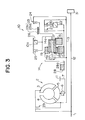
- FIG. 3 there is shown a structure of the automatic transmission AT in which the torque converter 2 is joined with an engine output shaft 1 and the multiple transmission gear mechanism 10 is connected with an output member of the torque converter 2.
- the torque converter 2 is provided with a pump 3 connected with the engine output shaft 1, a turbine 4 and a stator 5 mounted on a shaft 7 through one-way clutch 6.
- the gear mechanism 10 comprises an oil pump drive shaft 12 connected with the engine output shaft 1 at base end and with an oil pump 31 at a tip end thereof, a hollow turbine shaft 13 connected with the turbine 4 at base end outside of the oil pump drive shaft 12 and Ravigneaux-type planetary gear mechanism 14 around the turbine shaft 13.
- the planetary gear mechanism 14 is provided with a small sun gear 15 and a large sun gear 16 which are disposed side by side in a longitudinal direction of the transmission gear mechanism 10.
- the planetary gear mechanism 14 is also provided with a short pinion gear 18, a long pinon gear 17 meshed with the large sun gear 16 and the short pinion gear 18, and a ring gear 19 meshed with the long pinion gear 17.
- a 2-4 brake 23 provided with a brake drum 23a connected with the large sun gear 16 and a brake band 23b adapted to be engaged with the brake drum 23a so that when the 2-4 brake is engaged, the large sun gear is fixed.
- a reverse clutch 24 is arranged rearward of the brake 23 for controlling a power transmission between the large sun gear 16 and the turbine shaft 13 through the brake drum 23a to thereby establish a reverse shift stage.
- a low & reverse brake 25 between a carrier 14a of the planetary gear mechanism 14 and a casing 10a of the transmission gear mechanism 10 for controlling the engagement and disengagement between the carrier 14a and the casing 10a.
- the long pinion 17 is connected with the low & reverse brake 25 for fixing the long pinion 17 and with a second one-way clutch 26 arranged in a row with the brake 25 for allowing a rotation of the long pinion 17 in the same direction as the engine output shaft 1.
- a 3-4 clutch 27 is arranged in front of the planetary gear mechanism 14 for controlling the engagement and disengagement of between the carrier 14a and the turbine shaft 13.
- An output gear 28 disposed in front of the 3-4 clutch 27 is connected with the ring gear 19 through an output shaft 28a.
- Numerals 29 denote a lock-up clutch for directly connecting the engine output shaft 1 with the turbine shaft 13.
- the table 1 shows operations of the respective clutches and brakes in the respective shift gear stages of the transmission.
- reference O means that the corresponding element is under operation for transmitting a torque but the corresponding element to reference (O) is effected to transmit the power only when it functions as a driving element.
- the oil pump 31 discharges a hydraulic fluid to the hydraulic passage L1.
- the hydraulic pressure of the fluid is introduced into the pressure regulating valve 32.
- the pressure regulating valve 32 is controlled by the duty solenoid valve 33 to adjust the line pressure of the hydraulic control circuit 30.
- the hydraulic pressure from the pump 31 is reduced in a reducing valve 34 to a predetermined value.
- the hydraulic pressure is adjusted by virtue of a duty control of the solenoid valve 33 by controlling an amount of drain and introduced into the pressure regulating valve 32 as a pilot pressure therefor.
- the line pressure control of the hydraulic control circuit 30 is established.
- the regulated line pressure is introduced into a port g of a manual shift valve 35.
- the manual shift valve 35 is provided with a spool 35a connected with a select lever and associated with the lever so that the spool 35a can be moved in accordance with a manual operation for the select lever by a driver to the range D in which the gear shift operation is automatically made among the four forward gear stages, range 2 in which the gear shift operation is automatically made among the first through a third gear stages of the transmission, the range 1 in which the gear shift operation is automatically made between the first and second gear stages and a reverse range R, a parking range P, a neutral range N.
- the port g is communicated with ports a and e when set at the range 1, with ports a and c when set in the range 2 and D, and with a port f when set at the reverse range R.
- the port a of the manual shift valve 35 is connected with a 1-2 shift valve 36 through the hydraulic line L2.
- the 1-2 shift valve 36 is subjected to a pilot pressure which is adapted to be controlled by a 1-2 solenoid valve 37.
- the 1-2 solenoid valve 37 is turned off so that a spool 36a thereof is moved toward the left end to connect a hydraulic passage L3 communicated with an apply chamber 23c of the 2-4 brake 23 to a draining port.
- the 1-2 solenoid valve 37 is turned on so that the spool 36a is moved toward the right end in the drawing.
- the hydraulic pressure is introduced from the port a into the apply chamber 23c of the 2-4 brake 23.
- the 1-2 shift valve introduces the hydraulic pressure supplied from the port e of the manual shift valve 35 through a low reducing valve 38 into the low & reverse brake 25.
- the hydraulic pressure from the port a of the manual shift valve 35 is applied to a 2-3 shift valve 39 as a pilot pressure as well.
- the 2-3 shift valve 39 is connected with the port c of the manual valve 35 through a hydraulic passage L4.
- the pilot pressure therefor is controlled by a 2-3 solenoid valve 40.
- the 2-3 solenoid valve 40 When in the first and second stages, the 2-3 solenoid valve 40 is turned on causing a spool 39a of the valve 40 to be moved rightward so that a hydraulic passage L5 communicated with the 3-4 clutch 27 is connected with a draining passage to release the 3-4 clutch 27.
- the 2-3 solenoid valve 40 When in the third and fourth stages, the 2-3 solenoid valve 40 is turned off causing the spool 39a to be moved leftward so that the hydraulic pressure from the port c introduced into the hydraulic passage L5 establishes an engagement of the 3-4 clutch 27.
- the hydraulic passage L5 is also connected with a 3-4 shift valve 41 subjected to a pilot pressure controlled by a 3-4 solenoid valve 42.
- the 3-4 solenoid valve 42 is turned on causing a spool 41a of the valve 42 to be moved rightward so that a hydraulic passage L6 communicated with a release chamber 23d of the 2-4 brake 23 is connected with a draining passage.
- the 3-4 solenoid valve 42 is turned off causing the spool 42a to be moved leftward so that the hydraulic passage L6 is connected with the passage L5 connected with the 2-3 shift valve 39.
- the introduction of the hydraulic pressure is controlled in accordance with the operation of the 2-3 shift valve 39.
- the 3-4 shift valve 41 controls a communication between a hydraulic passage L7 connected with the port a of the manual shift valve 35 and a hydraulic passage L8 connected with the coast clutch 21 to thereby control the engagement and disengagement of the coast clutch 21.
- the operation of the 2-4 brake and 3-4 clutch 27 as frictional element can be accomplished through the control of solenoid valves 37, 40 and 42 as shown in Table 1.
- the control circuit 30 is provided with a 1-2 accumulator 43, a 2-3 accumulator 44, a 2-3 timing valve 45, a 3-2 timing valve 46 and a bypass valve 47 between the shift valves 36, 39 and 41 and the 2-4 brake 23 and the 3-4 clutch 27 for reducing a torque shock caused by switching operations thereof.
- control circuit 30 is provided with a N-D accumulator 48 connected with a hydraulic passage L9 which supplies the hydraulic pressure from the port a of the manual shift valve 35 so as to engage the forward clutch 20 in the first and second stages of the range D, a N-R accumulator connected with a hydraulic passage L10 which supplies the hydraulic pressure from the port f of the manual shift valve 35 so as to engage the reverse clutch 24 in the reverse range R, a lock-up control valve 50 for controlling the lock-up valve 29, a lock-up solenoid valve 51 for controlling the lock-up control valve 50 and a converter relief valve 52.
- the control unit 100 controls the line pressure of the control circuit 30 in accordance with flow charts shown in Figures 4 through 6, Figure 10, Figure 11 and Figure 14.
- the line pressure control is carried out by compensating the line pressure through a learning control and differently provided for the shift-up operation and the shift-down operation.
- the control unit 100 judges as to whether or not the transmission AT is in a shift operation in light of the shift pattern in step S1. If the judgment is No or the transmission AT is not in the shift operation, the control unit 100 carries out in step S2 a line pressure control in accordance with a routine provided for no-shift operation as shown in Figure 6. If the judgment is Yes in step S1, the control unit 100 carries out a routine for the shift operation as shown in Figure 7. Next, the control unit 100 judges whether or not a shift-up operation is made in step S4. If the judgment is Yes or the transmission AT is in the shift-up operation, the control unit 100 carries out a routine as shown in Figure 12 in which the line pressure is controlled based on a learning of shift operation time period.
- control unit 100 carries out a routine as shown in Figure 15 in which the line pressure is changed based on a learning control of a turbine speed increase. Then, the control unit 100 returns to the step S1.
- the control unit 100 reads the throttle opening and turbine speed from the sensors 101 and 102 respectively in step S11 and S12.
- the control unit 100 obtains the line pressure of the control circuit 30 in light of a map stored in a memory of the unit 100 in accordance with the throttle opening and the turbine speed.
- the control unit 100 determines a duty ratio DU for the duty solenoid valve 33 in accordance with the line pressure obtained in step S13.
- the control unit 100 sets a frequency for actuating the solenoid valve 33, for instance 35 Hz in the illustrated embodiment in step S15.
- step S16 the control unit 100 determines on-period in a single cycle by multiplying the duty ratio DU into a operating cycle.
- step S17 the control unit 100 actuates the solenoid valve 33 in accordance with the result of step S16 so as to accomplish the line pressure obtained in step S13 by applying a duty signal of normal frequency 35 Hz.
- the control unit 100 judges whether or not the shift operation is a shift-up operation in step S21.
- the control unit 100 reads the throttle opening in step S22 and determines the line pressure Pl in accordance with the throttle opening and gear stages involved in the shift-up operation. It will be understood that according to the illustrated embodiment, in determining the line pressure Pl, the gear stages are taken into account.
- the control unit 100 is provided in memory thereof with a map for obtaining the line pressure Pl in accordance with the throttle opening and the gear stages involved in the shift-up operation as shown in Figure 8(a).
- the line pressure obtained through step 23 will be further modified through the compensating procedure in Figure 12 in order to optimize the value.
- step S21 If the judgment of the step S21 is No or the transmission AT is in a shift-down operation, the control unit 100 further judges whether or not the shift-down operation is third to second stages in step S24. If Yes, the control unit 100 carries out steps S25 through S28. If No, the control in accordance with Figure 6 is carried out. It is necessary to make a timing control for engagement of the 2-4 brake 23 when the shift-down is made from the third to second stages by controlling the line pressure. In other shift-down operations, there is no need to control the line pressure because only disengagement action occurs on the 3-4 clutch 27 and the 2-4 brake 23 in this embodiment.
- control unit 100 reads the turbine speed in step S25 and determines a base line pressure Pl0 in accordance with the turbine speed in step 26.
- the control unit 100 determines the base line pressure Pl0 based on a map stored in a memory thereof in which the base line pressure Pl0 is provided in accordance with the turbine speed as shown in Figure 9.
- the base line pressure will be modified through a procedure of Figure 15 in order to optimize the value.
- the control unit 100 compensates the base line pressure Pl0 in accordance with a change speed in the throttle opening by employing and multiplying a compensation coefficient Ca into the base line pressure P10 in steps S27, S28.
- the coefficient is provided in accordance with the change speed in the throttle opening as shown in Figure 10.
- the control unit 100 determines the duty ratio DU of the solenoid valve 33 in step S29, sets the actuating frequency for actuating the valve 33 in step S30, calculates on-period of the solenoid in step S31 and actuates the valve 33 in step S32 so as to accomplish the line pressure value obtained through the step S23 or S28.
- the solenoid actuating frequency is set at 70 Hz higher than the value of step S15 in Figure 6 so as to get a responsive operation of the solenoid valve 33 .
- the control unit 100 reads the line pressure in step S35 and reads a temperature of the hydraulic fluid in the transmission AT in step S36. In step S37, the control unit 100 determines a base duty ratio DU0 in accordance with the hydraulic fluid temperature.
- the control unit 100 is provided with maps providing the base duty ratio DU0 based on the line pressure. Several maps are prepared with regard to respective temperatures of the hydraulic fluid since the relationship between the line pressure and the base duty ratio DU0 is changed in accordance with the temperature of the hydraulic fluid for better control. An accurate value of the base duty ratio DU0 can be obtained by means of a linear interpolation utilizing two maps even when the temperature of the hydraulic fluid takes an intermediate value.
- step S38 a time period is detected after starting engine.
- a compensation coefficient Cdu is obtained through a map in accordance with the time period after starting engine.
- the control unit 100 calculates the duty ratio DU by multiplying the coefficient Cdu into the base duty ratio DU0.
- This procedure is carried out for modifying the value of the line pressure obtained through step S23 of Figure 7 and stored in the memory of the control unit 100 in accordance with the shift operation time period.
- the turbine speed gradually decreases as the engaging force of the frictional elements increases.
- the engaging speed or the change speed of the engaging force of the frictional elements relates to the shift operation time period.
- the line pressure is compensated in accordance with the shift operation time period.
- the control unit 100 reads the turbine speed in step S41 and calculates a target turbine speed after the shift operation based on the actual turbine speed before the shift operation in step S42.
- step S43 the control unit 100 finds the termination of the shift operation when the difference between the target turbine speed and the actual turbine speed is smaller than a predetermined value and a change rate of the turbine speed is smaller than a predetermined value.
- the control unit 100 calculates the shift operation time period T in step S44.
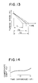
- step S45 the control unit 100 calculates a difference dT between the time period T and a target time period T0 which provides an appropriate speed change property of the turbine speed as shown by real line in Figure 13.
- step S46 the control unit 100 determines a coefficient Ct in accordance with the difference dT as shown in Figure 14. As the difference dT approaches 0, the coefficient Ct approaches 1. As the difference dT increases in a negative direction or the shift operation time period T takes a value T1 smaller than the value T0 as shown by a broken line in Figure 13, the coefficient Ct is reduced. When the difference dT increases in a positive direction or the shift operation time period T takes a value T2 larger than the target value T0 as shown in Figure 14, the coefficient Ct is increased.
- step S47 the line pressure Pl stored in the memory of the control unit 100 is replaced by a value obtained by multiplying the line pressure Pl into the coefficient Ct and renewed.
- the renewed value Pl is employed in the subsequent line pressure control.
- the learning control can be based on the turbine speed change during the shift operation.
- the learning control of the line pressure can be applied to the shift-down operation as well.
- the control unit 100 reads the turbine speed in step S51 and sets a target turbine speed N0 based on the turbine speed just before the shift operation in step S52.
- the control unit 100 calculates turbine speed change rate in step S53 and judges whether or not the turbine speed change rate is smaller than a predetermined value in step S54. If the turbine speed change rate is not smaller than the predetermined value, the control unit 100 returns to the step S53. When the turbine speed change rate is smaller than the predetermined value, the control unit 100 reads the turbine speed Ns just after the turbine speed change rate reduces below the predetermined value in step S55 and calculates a speed difference dN between the actual turbine speed Ns and the target turbine speed N0. In the illustrated embodiment, the turbine speed Ns exists in the vicinity of points x1, x0, x2 which are extreme points in respective turbine speed curves in Figure 16.
- the control unit 100 determines a compensating coefficient Cn in light of a map as shown Figure 17 in accordance with the speed difference dN in step S57.
- the coefficient approaches 1. If the speed difference dN increases in a positive direction as shown by a chain line in Figure 16, the coefficient Cn is increased. If the speed difference dN increases in a negative direction as shown by a broken line in Figure 16, the coefficient Cn is reduced as shown in Figure 17.
- step S58 the control unit 100 replaces the value of the base line pressure Pl0 by a new value which is obtained by multiplying the coefficient Cn into the value Pl0.
- the renewed line pressure Pl0 is stored in the memory and utilized for the subsequent control.
- the line pressure is modified to be increased when the turbine speed is increased as shown by the chain line in Figure 16.
- the line pressure is modified to be reduced when the turbine speed is decreased as shown by the broken line.
- the modified value of the line pressure is used for the subsequent line pressure control as a base value.
- the learning control according to the illustrated embodiment functions to lead the turbine speed change during the shift operation to a smaller value.
- the torque shock due to the shift operation can be effectively reduced by utilizing the above mentioned line pressure learning control.
- the duty solenoid valve 33 When the transmission is not under a shift operation, the duty solenoid valve 33 is actuated by a control signal of a normal frequency or 35 Hz in the illustrated embodiment so that an improved durability and reliable operation of the valve can be obtained.
- the solenoid valve 33 is actuated by a control signal of an increased frequency or 70 Hz in the illustrated embodiment during the shift-up and shift-down operation of the transmission so that a responsive operation of the solenoid valve 33 can be obtained.
- This facilitates the line pressure regulating valve 32 to control the line pressure of the hydraulic circuit 30 to enable a highly responsive switching action of the friction elements of the transmission. Such properly timed switching action of the friction elements is effected to reduce the torque shock during the shift operation.
Landscapes
- Engineering & Computer Science (AREA)
- General Engineering & Computer Science (AREA)
- Mechanical Engineering (AREA)
- Physics & Mathematics (AREA)
- Fluid Mechanics (AREA)
- Control Of Transmission Device (AREA)
- Structure Of Transmissions (AREA)
Description
- The present invention relates to a control system for an automatic transmission of motor vehicle, more specifically to a line pressure control for a hydraulic control mechanism of the transmission.
- Generally, an automatic transmission of a motor vehicle is provided with a torque converter, a transmitting mechanism employing a planetary gear mechanism. The transmission is also provided with a plurality of frictional elements such as clutches, brakes for establishing a desirable shift gear stage among the plurality of shift gear stages provided in the transmission. For this purpose, a hydraulic control circuit is provided with a plurality of solenoid valves for switching hydraulic passages in the circuit so that the frictional elements are engaged and disengaged to perform a desirable shift operation.
- Japanese Patent publication No. 54-2349 issued to Ford Motor corporation and published for opposition on February 6, 1979 discloses a basic electrical hydraulic control system for an automatic transmission in which regulator valves are provided for controlling a line pressure of hydraulic passages of circuit of the transmission, and pilot pressures of the regulator valves are controlled by solenoid valves.
- Switching operation of the hydraulic passages of the hydraulic circuit is necessary to be timely done, otherwise, there might be produced a torque shock resulting from unusual change in engine and/or turbine speed.
- In view of the above, there has been proposed controlling engaging force of the frictional elements to obviate the torque shock during shift operation of the transmission. For instance, published document GB-A-2 051 979 discloses a hydraulic control in which the hydraulic pressure introduced into the frictional element is controlled to gradually change the engaging force of the frictional elements and controlled to reduce the difference between a target time period for shift operation and an actual time period thereof.
- Published documents GB-A-2 160 264 and US-A-4 502 354 disclose similar control systems for obviating the torque shock due to the shift operation.
- Meanwhile, the frequency of control signal for the solenoid valves is determined taking account of reliability of operation, durability thereof and the like. It should be noted that as the frequency of the control signal is decreased, the response in the line pressure control is deteriorated but that if the frequency is too high, the durability and the reliability of the solenoid is badly affected.
- A known control system for controlling the transmission fluid pressure (EP-A-0 251 479) controls the pressure of a transmission fluid in order to hydraulically actuate appropriate elements to change the ratio between a driving input shaft and a driven output shaft. Pressurized transmission fluid is supplied to a solenoid valve which is operated by a pulse width modulated signal. The duty cycle of the pulse width modulated signal is adjusted to produce an appropriate transmission fluid pressure to perfom several functions as actuating a clutch, shifting gears. The known control system is further provided with temperature sensing means for sensing the temperature of the transmission fluid. Further, means are provided, responsive to the temperature sensing means for adjusting the characteristic of the electrical signal as a function of the temperature of the transmission fluid, that is by changing the frequency of the pulse width modulated signal. Thus, this known control system is particularly useful in maintaining a proper pressure control under cold weather conditions when the transmission fluid thickens and its viscosity increases. If the temperature of the transmission fluid is high, the pulse width modulated signal will be set to a high frequency, thereby achieving a fast response time. If the temperature is low, the frequency will be decreased preventing an insufficient fluid flow but still providing a satisfactory operation.
- It is therefore an object of the present invention to provide a line pressure control system of a hydraulic circuit for an automatic transmission which can suppress a torque shock during shift operation of the transmission effectively.
- It is another object of the present invention to provide a line pressure control system which can provide solenoid valves for controlling the line pressure of a hydraulic circuit of the transmission with an improved durability and reliability in operation.
- It is still another object of the present invention to provide a hydraulic control system for an automatic transmission which can provide a responsive line pressure control of hydraulic circuit to reduce the torque shock effectively during a shift operation.
- It is further object of the present invention to provide a hydraulic control system which controls the frequency of control signal for solenoid valves which controls the line pressure of the hydraulic control system so as to provide a desirable switching operation in the transmission during the shift operation.
- The above and other objects of the present invention can be accomplished by a hydraulic pressure control system for an automatic transmission comprising the features of
claim 1. - The frequency control device may be provided in a control section in the solenoid valve. The control signal may be a duty signal of a certain duty ratio determined by a control unit as constituted by a microcomputer.
- According to the present invention, the frequency of the control signal for the solenoid valve is maintained at a proper value in view of the durability and the reliability in operation when the transmission is not under a shift operation. The frequency is increased to accomplish a responsive switching operation during the shift operation to reduce a torque shock.
- The above and other features of the present invention will be apparent from the following description taking reference to the accompanying drawings.
-
- Figure 1 is a schematic view of a hydraulic control system in accordance with the present invention;
- Figure 2 is a view showing a control signal applied to a duty solenoid valve controlling a line pressure through a regulating valve;
- Figure 3 is a sectional view showing an automatic transmission provided with torque converter and a hydraulic circuit to which the present invention can be applied;
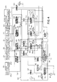
- Figure 4 is a hydraulic control circuit in accordance with a preferred embodiment of the present invention;
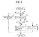
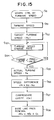
- Figure 5 is a flow chart of a main routine of a line pressure control;
- Figure 6 is a flow chart of a routine of a line pressure control under a no-shift operation;
- Figure 7 is a flow chart of a routine of a line pressure control during a shift operation;
- Figure 8(a) shows a map providing a relationship between the line pressure, throttle opening and the gear stages involved in the shift operation;
- Figure 8(b) is a graphical representation showing a relationship between the throttle opening and the line pressure;
- Figure 9 shows a map providing a relationship between the line pressure, turbine speed and the gear stages involved in the shift operation;
- Figure 10 is a graphical representation showing a relationship between a throttle opening change speed and a coefficient for compensating the line pressure;
- Figure 11 is a flow chart of a routine for determining a duty ratio for a solenoid valve;
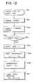
- Figure 12 is a flow chart of a routine for compensating the line pressure by means of a learning control based on a shift operation time period;
- Figure 13 is a graphical representation showing a turbine speed change during a shift-up operation;
- Figure 14 is a graphical representation showing a property of a compensating coefficient based on the shift operation time period;
- Figure 15 is a flow chart of a routine for compensating the line pressure by means of a learning control based on the turbine speed change in a shift-down operation;
- Figure 16 is a graphical representation showing the turbine speed change during the shift-down operation;
- Figure 17 is a graphical representation showing a property of a compensating coefficient based on the turbine speed change in the shift-down operation.
- Referring to the drawings, specifically to Figure 1, an automatic transmission AT is provided with a
torque converter 2, a multiple stagetransmission gear mechanism 10 and ahydraulic control circuit 30 therefor. Thetransmission gear mechanism 10 is provided with a plurality of frictional elements, such as clutches and brakes for switching power transmitting path therein. The engagement and disengagement of the frictional elements are controlled by thehydraulic control circuit 30. Thehydraulic control circuit 30 is provided with apressure regulating valve 32 for adjusting a line pressure introduced into the frictional elements and aduty solenoid valve 33 for controlling the regulatingvalve 32, which constitute a line pressure control mechanism. - There is provided an electronic control unit (ECU) 100 constituted by a microcomputer and the like for controlling the
hydraulic control circuit 30. Thecontrol unit 100 receives a signal from athrottle sensor 101 for detecting an opening of throttle valve (not shown),turbine speed sensor 102 for detecting turbine speed or rotation speed of input element of thetransmission gear mechanism 10 and the like. - The
control unit 100 includes a linepressure control device 103 for controlling theduty solenoid valve 33 to thereby control the line pressure of thehydraulic control circuit 30, andfrequency control device 104 for changing a frequency of control signal for theduty solenoid valve 33 during shift operation of thetransmission gear mechanism 10. - The
control unit 100 controlssolenoid valve up solenoid valve 51 to thereby control a lock-up clutch 29 for establishing a lock-up condition. - Referring to Figure 2, there is shown the control signal applied to the
duty solenoid valve 33. The signal is of a duty signal constituted by a continuous on-off signal wherein a ratio of on-period to a single cycle of the signal is defined as a duty ratio. The duty ratio is controlled in accordance with engine operating condition. In addition, the frequency of the control signal for theduty solenoid valve 33 is also changed during the shift operation of the transmission AT. According to the illustrated embodiment of the present invention, the frequency is increased from 30 Hz to 70 Hz during the shift operation as shown in Figure 2. - Referring to Figure 3, there is shown a structure of the automatic transmission AT in which the
torque converter 2 is joined with anengine output shaft 1 and the multipletransmission gear mechanism 10 is connected with an output member of thetorque converter 2. - The
torque converter 2 is provided with apump 3 connected with theengine output shaft 1, aturbine 4 and a stator 5 mounted on a shaft 7 through one-way clutch 6. - The
gear mechanism 10 comprises an oilpump drive shaft 12 connected with theengine output shaft 1 at base end and with anoil pump 31 at a tip end thereof, a hollow turbine shaft 13 connected with theturbine 4 at base end outside of the oilpump drive shaft 12 and Ravigneaux-typeplanetary gear mechanism 14 around the turbine shaft 13. Theplanetary gear mechanism 14 is provided with a small sun gear 15 and alarge sun gear 16 which are disposed side by side in a longitudinal direction of thetransmission gear mechanism 10. Theplanetary gear mechanism 14 is also provided with ashort pinion gear 18, along pinon gear 17 meshed with thelarge sun gear 16 and theshort pinion gear 18, and aring gear 19 meshed with thelong pinion gear 17. - There are provided a
forward clutch 20 and a coast clutch 21 side by side as frictional element between the turbine shaft 13 and the small sun gear 15. The small sun gear 15 is connected with the turbine shaft 13 through the forward clutch 20 located rearward of thelarge sun gear 16 and a first one-way clutch 22 connected with theforward clutch 20 for preventing a reverse rotation of the turbine shaft 13. Thecoast clutch 21 is also arranged between theturbine shaft 4 and the small sun gear 15 in a row with theforward clutch 20 and the one-way clutch 22. - Outside of the
coast clutch 21, there is disposed a 2-4brake 23 provided with a brake drum 23a connected with thelarge sun gear 16 and abrake band 23b adapted to be engaged with the brake drum 23a so that when the 2-4 brake is engaged, the large sun gear is fixed. A reverse clutch 24 is arranged rearward of thebrake 23 for controlling a power transmission between thelarge sun gear 16 and the turbine shaft 13 through the brake drum 23a to thereby establish a reverse shift stage. - There is provided a low &
reverse brake 25 between acarrier 14a of theplanetary gear mechanism 14 and a casing 10a of thetransmission gear mechanism 10 for controlling the engagement and disengagement between thecarrier 14a and the casing 10a. Thelong pinion 17 is connected with the low &reverse brake 25 for fixing thelong pinion 17 and with a second one-way clutch 26 arranged in a row with thebrake 25 for allowing a rotation of thelong pinion 17 in the same direction as theengine output shaft 1. - A 3-4
clutch 27 is arranged in front of theplanetary gear mechanism 14 for controlling the engagement and disengagement of between thecarrier 14a and the turbine shaft 13. Anoutput gear 28 disposed in front of the 3-4clutch 27 is connected with thering gear 19 through an output shaft 28a.Numerals 29 denote a lock-up clutch for directly connecting theengine output shaft 1 with the turbine shaft 13. - The multiple
transmission gear mechanism 10 as illustrated is provided with four shift gear stages for forward movement and one shift gear stage for reverse movement. Theclutches brakes - The table 1 shows operations of the respective clutches and brakes in the respective shift gear stages of the transmission.

- In the table 1, reference O means that the corresponding element is under operation for transmitting a torque but the corresponding element to reference (O) is effected to transmit the power only when it functions as a driving element.
- Hereinafter, the
hydraulic circuit 30 will be explained in connection with operations of the above frictional elements taking reference to Figure 4. - As shown in Figure 4, the
oil pump 31 discharges a hydraulic fluid to the hydraulic passage L1. The hydraulic pressure of the fluid is introduced into thepressure regulating valve 32. Thepressure regulating valve 32 is controlled by theduty solenoid valve 33 to adjust the line pressure of thehydraulic control circuit 30. In detail, the hydraulic pressure from thepump 31 is reduced in a reducingvalve 34 to a predetermined value. Thereafter, the hydraulic pressure is adjusted by virtue of a duty control of thesolenoid valve 33 by controlling an amount of drain and introduced into thepressure regulating valve 32 as a pilot pressure therefor. Thus, the line pressure control of thehydraulic control circuit 30 is established. The regulated line pressure is introduced into a port g of amanual shift valve 35. Themanual shift valve 35 is provided with aspool 35a connected with a select lever and associated with the lever so that thespool 35a can be moved in accordance with a manual operation for the select lever by a driver to the range D in which the gear shift operation is automatically made among the four forward gear stages,range 2 in which the gear shift operation is automatically made among the first through a third gear stages of the transmission, therange 1 in which the gear shift operation is automatically made between the first and second gear stages and a reverse range R, a parking range P, a neutral range N. - The port g is communicated with ports a and e when set at the
range 1, with ports a and c when set in therange 2 and D, and with a port f when set at the reverse range R. - The port a of the
manual shift valve 35 is connected with a 1-2shift valve 36 through the hydraulic line L2. The 1-2shift valve 36 is subjected to a pilot pressure which is adapted to be controlled by a 1-2solenoid valve 37. When the shift stage is the first stage, the 1-2solenoid valve 37 is turned off so that aspool 36a thereof is moved toward the left end to connect a hydraulic passage L3 communicated with an applychamber 23c of the 2-4brake 23 to a draining port. When the shift stage is the second to fourth stages, the 1-2solenoid valve 37 is turned on so that thespool 36a is moved toward the right end in the drawing. As a result, the hydraulic pressure is introduced from the port a into the applychamber 23c of the 2-4brake 23. When the shift stage is the first stage in therange 1, the 1-2 shift valve introduces the hydraulic pressure supplied from the port e of themanual shift valve 35 through a low reducingvalve 38 into the low &reverse brake 25. - The hydraulic pressure from the port a of the
manual shift valve 35 is applied to a 2-3shift valve 39 as a pilot pressure as well. The 2-3shift valve 39 is connected with the port c of themanual valve 35 through a hydraulic passage L4. The pilot pressure therefor is controlled by a 2-3solenoid valve 40. - When in the first and second stages, the 2-3
solenoid valve 40 is turned on causing a spool 39a of thevalve 40 to be moved rightward so that a hydraulic passage L5 communicated with the 3-4clutch 27 is connected with a draining passage to release the 3-4clutch 27. - When in the third and fourth stages, the 2-3
solenoid valve 40 is turned off causing the spool 39a to be moved leftward so that the hydraulic pressure from the port c introduced into the hydraulic passage L5 establishes an engagement of the 3-4clutch 27. - The hydraulic passage L5 is also connected with a 3-4
shift valve 41 subjected to a pilot pressure controlled by a 3-4solenoid valve 42. When the shift stage is the first, second and fourth stages in the range D, and the first in therange 2, the 3-4solenoid valve 42 is turned on causing a spool 41a of thevalve 42 to be moved rightward so that a hydraulic passage L6 communicated with arelease chamber 23d of the 2-4brake 23 is connected with a draining passage. - When the shift stage is the third stage in the range D, second and third stage in the
range 2 and the first and second stages in therange 1, the 3-4solenoid valve 42 is turned off causing the spool 42a to be moved leftward so that the hydraulic passage L6 is connected with the passage L5 connected with the 2-3shift valve 39. As a result, the introduction of the hydraulic pressure is controlled in accordance with the operation of the 2-3shift valve 39. - The 3-4
shift valve 41 controls a communication between a hydraulic passage L7 connected with the port a of themanual shift valve 35 and a hydraulic passage L8 connected with the coast clutch 21 to thereby control the engagement and disengagement of thecoast clutch 21. Thus, the operation of the 2-4 brake and 3-4clutch 27 as frictional element can be accomplished through the control ofsolenoid valves - The
control circuit 30 is provided with a 1-2accumulator 43, a 2-3accumulator 44, a 2-3timing valve 45, a 3-2timing valve 46 and abypass valve 47 between theshift valves brake 23 and the 3-4clutch 27 for reducing a torque shock caused by switching operations thereof. - In addition, the
control circuit 30 is provided with aN-D accumulator 48 connected with a hydraulic passage L9 which supplies the hydraulic pressure from the port a of themanual shift valve 35 so as to engage the forward clutch 20 in the first and second stages of the range D, a N-R accumulator connected with a hydraulic passage L10 which supplies the hydraulic pressure from the port f of themanual shift valve 35 so as to engage the reverse clutch 24 in the reverse range R, a lock-upcontrol valve 50 for controlling the lock-upvalve 29, a lock-upsolenoid valve 51 for controlling the lock-upcontrol valve 50 and aconverter relief valve 52. - The
control unit 100 controls the line pressure of thecontrol circuit 30 in accordance with flow charts shown in Figures 4 through 6, Figure 10, Figure 11 and Figure 14. - Referring to Figure 5, there is shown a main routine of the control for the
hydraulic circuit 30. - According to the illustrated embodiment, the line pressure control is carried out by compensating the line pressure through a learning control and differently provided for the shift-up operation and the shift-down operation.
- The
control unit 100 judges as to whether or not the transmission AT is in a shift operation in light of the shift pattern in step S1. If the judgment is No or the transmission AT is not in the shift operation, thecontrol unit 100 carries out in step S2 a line pressure control in accordance with a routine provided for no-shift operation as shown in Figure 6. If the judgment is Yes in step S1, thecontrol unit 100 carries out a routine for the shift operation as shown in Figure 7. Next, thecontrol unit 100 judges whether or not a shift-up operation is made in step S4. If the judgment is Yes or the transmission AT is in the shift-up operation, thecontrol unit 100 carries out a routine as shown in Figure 12 in which the line pressure is controlled based on a learning of shift operation time period. - If the judgment is No or the transmission AT is in a shift-down operation, the
control unit 100 carries out a routine as shown in Figure 15 in which the line pressure is changed based on a learning control of a turbine speed increase. Then, thecontrol unit 100 returns to the step S1. - In case of no-shift operation, the line pressure is controlled in accordance with the procedure shown in Figure 6.
- The
control unit 100 reads the throttle opening and turbine speed from thesensors - Next, the
control unit 100 obtains the line pressure of thecontrol circuit 30 in light of a map stored in a memory of theunit 100 in accordance with the throttle opening and the turbine speed. In step S14, thecontrol unit 100 determines a duty ratio DU for theduty solenoid valve 33 in accordance with the line pressure obtained in step S13. Thecontrol unit 100 sets a frequency for actuating thesolenoid valve 33, forinstance 35 Hz in the illustrated embodiment in step S15. In step S16, thecontrol unit 100 determines on-period in a single cycle by multiplying the duty ratio DU into a operating cycle. In step S17, thecontrol unit 100 actuates thesolenoid valve 33 in accordance with the result of step S16 so as to accomplish the line pressure obtained in step S13 by applying a duty signal ofnormal frequency 35 Hz. - The line pressure control during the shift operation of step S3 in Figure 5 is carried out in accordance with a routine shown in Figure 7.
- At first, the
control unit 100 judges whether or not the shift operation is a shift-up operation in step S21. In shift-up operation, thecontrol unit 100 reads the throttle opening in step S22 and determines the line pressure Pl in accordance with the throttle opening and gear stages involved in the shift-up operation. It will be understood that according to the illustrated embodiment, in determining the line pressure Pl, the gear stages are taken into account. For this purpose, thecontrol unit 100 is provided in memory thereof with a map for obtaining the line pressure Pl in accordance with the throttle opening and the gear stages involved in the shift-up operation as shown in Figure 8(a). - Resultant line pressure properties are obtained in accordance with gear stages involved in the shift operation as shown in Figure 8(b). The line pressures obtained through the above procedure are lower than the value under a conventional control as shown by a chain line. Thus, precise control of the line pressure can be accomplished by the present invention.
- The line pressure obtained through
step 23 will be further modified through the compensating procedure in Figure 12 in order to optimize the value. - If the judgment of the step S21 is No or the transmission AT is in a shift-down operation, the
control unit 100 further judges whether or not the shift-down operation is third to second stages in step S24. If Yes, thecontrol unit 100 carries out steps S25 through S28. If No, the control in accordance with Figure 6 is carried out. It is necessary to make a timing control for engagement of the 2-4brake 23 when the shift-down is made from the third to second stages by controlling the line pressure. In other shift-down operations, there is no need to control the line pressure because only disengagement action occurs on the 3-4clutch 27 and the 2-4brake 23 in this embodiment. - In the shift-down operation of the third to second stages, the
control unit 100 reads the turbine speed in step S25 and determines a base line pressure Pl0 in accordance with the turbine speed instep 26. - According to the procedure of the illustrated embodiment, the
control unit 100 determines the base line pressure Pl0 based on a map stored in a memory thereof in which the base line pressure Pl0 is provided in accordance with the turbine speed as shown in Figure 9. The base line pressure will be modified through a procedure of Figure 15 in order to optimize the value. - The
control unit 100 compensates the base line pressure Pl0 in accordance with a change speed in the throttle opening by employing and multiplying a compensation coefficient Ca into the base line pressure P10 in steps S27, S28. The coefficient is provided in accordance with the change speed in the throttle opening as shown in Figure 10. - Next, the
control unit 100 determines the duty ratio DU of thesolenoid valve 33 in step S29, sets the actuating frequency for actuating thevalve 33 in step S30, calculates on-period of the solenoid in step S31 and actuates thevalve 33 in step S32 so as to accomplish the line pressure value obtained through the step S23 or S28. In this control, the solenoid actuating frequency is set at 70 Hz higher than the value of step S15 in Figure 6 so as to get a responsive operation of thesolenoid valve 33 . - Referring to Figure 11, there is shown a procedure for determining the duty ratio DU utilized in step S15 of Figure 6 and in step S29 of Figure 7.
- The
control unit 100 reads the line pressure in step S35 and reads a temperature of the hydraulic fluid in the transmission AT in step S36. In step S37, thecontrol unit 100 determines a base duty ratio DU0 in accordance with the hydraulic fluid temperature. Thecontrol unit 100 is provided with maps providing the base duty ratio DU0 based on the line pressure. Several maps are prepared with regard to respective temperatures of the hydraulic fluid since the relationship between the line pressure and the base duty ratio DU0 is changed in accordance with the temperature of the hydraulic fluid for better control. An accurate value of the base duty ratio DU0 can be obtained by means of a linear interpolation utilizing two maps even when the temperature of the hydraulic fluid takes an intermediate value. - It is preferable to take into account of affection by air and the like in the hydraulic fluid at the initial stage of the operation of the transmission. For this purpose, in step S38, a time period is detected after starting engine. According to the illustrated control, a compensation coefficient Cdu is obtained through a map in accordance with the time period after starting engine. In
step 40, thecontrol unit 100 calculates the duty ratio DU by multiplying the coefficient Cdu into the base duty ratio DU0. - Referring to Figure 12, there is shown a procedure for compensating the line pressure by means of a learning control of shift operation time period appeared in step 5 of Figure 5.
- This procedure is carried out for modifying the value of the line pressure obtained through step S23 of Figure 7 and stored in the memory of the
control unit 100 in accordance with the shift operation time period. - In the shift-up operation, the turbine speed gradually decreases as the engaging force of the frictional elements increases. The engaging speed or the change speed of the engaging force of the frictional elements relates to the shift operation time period. In view of the above, according to the illustrated embodiment, the line pressure is compensated in accordance with the shift operation time period.
- The
control unit 100 reads the turbine speed in step S41 and calculates a target turbine speed after the shift operation based on the actual turbine speed before the shift operation in step S42. In step S43, thecontrol unit 100 finds the termination of the shift operation when the difference between the target turbine speed and the actual turbine speed is smaller than a predetermined value and a change rate of the turbine speed is smaller than a predetermined value. When the termination of the shift operation is found, thecontrol unit 100 calculates the shift operation time period T in step S44. In step S45, thecontrol unit 100 calculates a difference dT between the time period T and a target time period T0 which provides an appropriate speed change property of the turbine speed as shown by real line in Figure 13. - In step S46, the
control unit 100 determines a coefficient Ct in accordance with the difference dT as shown in Figure 14. As the difference dT approaches 0, the coefficient Ct approaches 1. As the difference dT increases in a negative direction or the shift operation time period T takes a value T1 smaller than the value T0 as shown by a broken line in Figure 13, the coefficient Ct is reduced. When the difference dT increases in a positive direction or the shift operation time period T takes a value T2 larger than the target value T0 as shown in Figure 14, the coefficient Ct is increased. - In step S47, the line pressure Pl stored in the memory of the
control unit 100 is replaced by a value obtained by multiplying the line pressure Pl into the coefficient Ct and renewed. The renewed value Pl is employed in the subsequent line pressure control. Thus, the learning control based the shift operation time period can be accomplished. - The learning control can be based on the turbine speed change during the shift operation.
- The learning control of the line pressure can be applied to the shift-down operation as well.
- Referring to Figure 15, there is shown a compensating routine in the form of flow chart. This compensating routine constitutes a content of step S6 in Figure 5 in which the line pressure is compensated in view of a fluctuation of the turbine speed in case of shift operation of the transmission AT. The compensating routine modifies the value of the base line pressure Pl0 obtained through step S26 in Figure 7 and stored in the memory of the
control unit 100 by means of a learning control based on the fluctuation of the turbine speed. - The
control unit 100 reads the turbine speed in step S51 and sets a target turbine speed N0 based on the turbine speed just before the shift operation in step S52. - The
control unit 100 calculates turbine speed change rate in step S53 and judges whether or not the turbine speed change rate is smaller than a predetermined value in step S54. If the turbine speed change rate is not smaller than the predetermined value, thecontrol unit 100 returns to the step S53. When the turbine speed change rate is smaller than the predetermined value, thecontrol unit 100 reads the turbine speed Ns just after the turbine speed change rate reduces below the predetermined value in step S55 and calculates a speed difference dN between the actual turbine speed Ns and the target turbine speed N0. In the illustrated embodiment, the turbine speed Ns exists in the vicinity of points x1, x0, x2 which are extreme points in respective turbine speed curves in Figure 16. - The
control unit 100 determines a compensating coefficient Cn in light of a map as shown Figure 17 in accordance with the speed difference dN in step S57. - As the speed difference dN approaches 0, the coefficient approaches 1. If the speed difference dN increases in a positive direction as shown by a chain line in Figure 16, the coefficient Cn is increased. If the speed difference dN increases in a negative direction as shown by a broken line in Figure 16, the coefficient Cn is reduced as shown in Figure 17.
- In step S58, the
control unit 100 replaces the value of the base line pressure Pl0 by a new value which is obtained by multiplying the coefficient Cn into the value Pl0. The renewed line pressure Pl0 is stored in the memory and utilized for the subsequent control. Thus, the learning control of the line pressure based on the turbine speed change rate can be accomplished. - According to the learning control of the illustrated embodiment in the case of shift-down operation, the line pressure is modified to be increased when the turbine speed is increased as shown by the chain line in Figure 16. On the other hand, the line pressure is modified to be reduced when the turbine speed is decreased as shown by the broken line.
- The modified value of the line pressure is used for the subsequent line pressure control as a base value. Thus, the learning control according to the illustrated embodiment functions to lead the turbine speed change during the shift operation to a smaller value. As a result, the torque shock due to the shift operation can be effectively reduced by utilizing the above mentioned line pressure learning control.
- Although the learning control of the line pressure based on the turbine speed is explained in connection with a shift-down operation, the control can be applied to the shift-up operation.
- When the transmission is not under a shift operation, the
duty solenoid valve 33 is actuated by a control signal of a normal frequency or 35 Hz in the illustrated embodiment so that an improved durability and reliable operation of the valve can be obtained. On the other hand, thesolenoid valve 33 is actuated by a control signal of an increased frequency or 70 Hz in the illustrated embodiment during the shift-up and shift-down operation of the transmission so that a responsive operation of thesolenoid valve 33 can be obtained. This facilitates the linepressure regulating valve 32 to control the line pressure of thehydraulic circuit 30 to enable a highly responsive switching action of the friction elements of the transmission. Such properly timed switching action of the friction elements is effected to reduce the torque shock during the shift operation.
Claims (14)
- A hydraulic pressure control system for an automatic transmission (AT) comprising;
a multiple transmission gear mechanism (10) having a plurality of gear stages and frictional elements for switching power transmitting paths in the transmission gear mechanism (10),
hydraulic control mechanism (30) for controlling engagement and disengagement of the frictional elements to establish one of said gear stages,
line pressure control valve means (32) for controlling line pressure (Pl) of said hydraulic control mechanism (30),
solenoid valve means (33) for receiving a control signal and controlling a pilot pressure based on the control signal allowing the line pressure control valve means (32) to control the line pressure (Pl),- shift operation detecting means (100) for detecting an actual shift operation- frequency control means (104) responsive to said shift operation detecting means (100) for increasing the frequency of the control signal for the solenoid valve means (33) during a shift operation of the transmission (AT). - A hydraulic pressure control system as recited in claim 1 further comprising speed detecting means (102) for detecting a rotation speed of an input member (13) of the transmission gear mechanism, compensation means (Cn) for compensating the line pressure based on the rotation speed of said input member.
- A hydraulic pressure control system as recited in claim 2 said compensation means comprises shift time detecting means (S44) for detecting an actual shift operation time period based on a speed change rate of said input member, and target time setting means for setting a target shift operation time period in the shift operation, the compensation means (Ct) compensating the line pressure in accordance with a time difference (dT) between the actual shift operation time period (T) and the target shift operation time period (T0).
- A hydraulic pressure control system as recited in claim 3 wherein said compensation means compensates the line pressure to be reduced when the actual shift operation time period is smaller than the target shift operation time period.
- A hydraulic pressure control system as recited in claim 3 wherein said compensation means compensates the line pressure to be increased when the actual shift operation time period is longer than the target shift operation time period.
- A hydraulic pressure control system as recited in claim 3 wherein said compensation means compensates the line pressure by means of a learning control based on the shift operation time period (S5).
- A hydraulic pressure control system as recited in claim 3 wherein the compensation means further comprises speed change rate detecting means for detecting a speed change rate of the input member (13) based on the signal from the speed detecting means, and the compensation means finding a termination of the shift operation when the speed change rate reduces below a predetermined value.
- A hydraulic pressure control system as recited in claim 3 wherein the shift operation is a shift-up operation.
- A hydraulic pressure control system as recited in claim 2 wherein said compensation means comprises target speed setting means for setting a target speed of said input member in the shift operation, the compensation means compensating the line pressure based on a speed difference (dN) between actual speed obtained through the speed detecting means (Ns) and the target speed (N0).
- A hydraulic pressure control system as recited in claim 9 wherein said compensation means compensates the line pressure by means of a learning control based on the speed of the input member (S6).
- A hydraulic pressure control system as recited in claim 9 wherein said compensation means compensates the line pressure to be reduced when the actual speed of the input member (13) is smaller than the target speed (N0).
- A hydraulic pressure control system as recited in claim 9 wherein said compensation means compensates the line pressure to be increased when the actual speed of the input member (13) is greater than the target speed (N0).
- A hydraulic pressure control system as recited in claim 9 wherein the shift operation is a shift-down operation.
- A hydraulic pressure control system as recited in claim 2 wherein said compensation means compensates the line pressure based on a temperature of a hydraulic fluid in said transmission (S36).
Applications Claiming Priority (2)
| Application Number | Priority Date | Filing Date | Title |
|---|---|---|---|
| JP63266997A JPH0633813B2 (en) | 1988-10-22 | 1988-10-22 | Line pressure control device for automatic transmission |
| JP266997/88 | 1988-10-22 |
Publications (3)
| Publication Number | Publication Date |
|---|---|
| EP0366003A2 EP0366003A2 (en) | 1990-05-02 |
| EP0366003A3 EP0366003A3 (en) | 1991-06-26 |
| EP0366003B1 true EP0366003B1 (en) | 1994-01-26 |
Family
ID=17438628
Family Applications (1)
| Application Number | Title | Priority Date | Filing Date |
|---|---|---|---|
| EP89119407A Expired - Lifetime EP0366003B1 (en) | 1988-10-22 | 1989-10-19 | Line pressure control system for automatic transmission |
Country Status (4)
| Country | Link |
|---|---|
| US (1) | US5079971A (en) |
| EP (1) | EP0366003B1 (en) |
| JP (1) | JPH0633813B2 (en) |
| DE (1) | DE68912706T2 (en) |
Families Citing this family (20)
| Publication number | Priority date | Publication date | Assignee | Title |
|---|---|---|---|---|
| KR920010906B1 (en) * | 1989-08-23 | 1992-12-21 | 마쯔다 가부시기가이샤 | Line pressure control system for automatic transmission |
| US5214984A (en) * | 1990-12-06 | 1993-06-01 | Jatco Corporation | Pressure control system for automotive automatic power transmission with feature of fluid pressure dependent actuator control |
| JP2657007B2 (en) * | 1991-04-15 | 1997-09-24 | 三菱電機株式会社 | Shift hydraulic control device for electronically controlled automatic transmission |
| JP2959284B2 (en) * | 1991-07-31 | 1999-10-06 | 三菱自動車工業株式会社 | Transmission control device for automatic transmission |
| US5349885A (en) * | 1991-09-03 | 1994-09-27 | Mazda Motor Corporation | Hydraulic control system for controlling line pressure based on backtorque and throttle rate in an automatic transmission |
| JPH05203038A (en) * | 1992-01-28 | 1993-08-10 | Jatco Corp | Control device for automatic transmission |
| US5404301A (en) * | 1993-06-07 | 1995-04-04 | Eaton Corporation | Method and apparatus of vehicle transmission control by assured minimum pulse width |
| US5505675A (en) * | 1993-11-22 | 1996-04-09 | Mazda Motor Corporation | Hydraulic control system of automatic transmission |
| GB2286641B (en) * | 1994-02-17 | 1998-01-07 | Acg France | Method and apparatus for controlling a gear change in an automatic transmission |
| JP3536533B2 (en) * | 1996-06-11 | 2004-06-14 | トヨタ自動車株式会社 | Shift control device for automatic transmission for vehicle |
| JP3536537B2 (en) * | 1996-06-28 | 2004-06-14 | トヨタ自動車株式会社 | Shift control device for automatic transmission for vehicle |
| DE19727358B4 (en) * | 1996-07-02 | 2008-02-07 | Conti Temic Microelectronic Gmbh | Pressure medium system and a method for their use |
| KR100411032B1 (en) * | 1997-06-18 | 2004-05-10 | 현대자동차주식회사 | Power train for automatic transmission |
| DE19757603B4 (en) * | 1997-12-23 | 2004-03-18 | Hyundai Motor Company | Pressure adjustment valve and hydraulic control system of an automatic transmission equipped with the same |
| KR100302809B1 (en) * | 1999-06-30 | 2001-09-22 | 이계안 | Methode for controlling shift automatic transmission of vehicle |
| US6671577B2 (en) | 2000-12-01 | 2003-12-30 | United States Postal Service | System and method for directly connecting an advanced facer canceler system to a delivery bar code sorter |
| JP2002276799A (en) * | 2001-01-11 | 2002-09-25 | Jatco Ltd | Shift control device for automatic transmission |
| JP5126144B2 (en) * | 2009-03-27 | 2013-01-23 | アイシン・エィ・ダブリュ株式会社 | Electromagnetic valve device and power transmission device having the same |
| CN104455374B (en) * | 2014-11-21 | 2016-09-07 | 湖北航天技术研究院特种车辆技术中心 | Possesses the gearshift electrohydraulic system of emergent gear automatic switching function |
| DE102015120796B4 (en) * | 2014-12-15 | 2019-07-18 | Hyundai Autron Co., Ltd. | Shift control method and shift control device for a vehicle |
Citations (1)
| Publication number | Priority date | Publication date | Assignee | Title |
|---|---|---|---|---|
| EP0251479A1 (en) * | 1986-06-27 | 1988-01-07 | Borg-Warner Automotive, Inc. | Control systeem for controlling transmission fluid pressure |
Family Cites Families (22)
| Publication number | Priority date | Publication date | Assignee | Title |
|---|---|---|---|---|
| JPS4930051A (en) * | 1972-07-17 | 1974-03-18 | ||
| JPS542349A (en) * | 1977-06-07 | 1979-01-09 | Idemitsu Kosan Co Ltd | Sublimable multi-layered composite |
| US4283970A (en) * | 1979-07-02 | 1981-08-18 | General Motors Corporation | Automatic transmission line pressure control |
| JPS5747056A (en) * | 1980-09-04 | 1982-03-17 | Nissan Motor Co Ltd | Oil pressure control device for automatic transmission |
| JPS6049793B2 (en) * | 1981-03-30 | 1985-11-05 | 日産自動車株式会社 | Lock-up control device for lock-up automatic transmission |
| JPS58137652A (en) * | 1982-02-12 | 1983-08-16 | Komatsu Ltd | Method of minimizing shift shock of transmission |
| JPS5962756A (en) * | 1982-10-01 | 1984-04-10 | Mazda Motor Corp | Automatic electronic control transmission |
| JPS6148021A (en) * | 1984-08-15 | 1986-03-08 | Toshiba Corp | Reset circuit of computer |
| JPS6184446A (en) * | 1984-09-29 | 1986-04-30 | Mitsubishi Motors Corp | Method of setting initial hydraulic pressure in vehicle automatic speed change gear unit |
| JPS6217328A (en) * | 1985-07-15 | 1987-01-26 | Diesel Kiki Co Ltd | Control device for internal-combustion vehicle |
| DE3630768C2 (en) * | 1985-09-14 | 1997-04-03 | Volkswagen Ag | Control device for an automatic motor vehicle gearbox |
| JPS62215158A (en) * | 1986-03-14 | 1987-09-21 | Mazda Motor Corp | Fluid pressure controlling device for automatic transmission |
| JPS633183A (en) * | 1986-06-20 | 1988-01-08 | Matsushita Refrig Co | Finned heat exchanger |
| JPS6314053U (en) * | 1986-07-07 | 1988-01-29 | ||
| JP2505755B2 (en) * | 1986-07-10 | 1996-06-12 | 日産自動車株式会社 | Hydraulic pressure control device for automatic transmission |
| JPS6353349A (en) * | 1986-08-20 | 1988-03-07 | Aisin Warner Ltd | Electronically controlled automatic transmission |
| JPS6367448A (en) * | 1986-09-10 | 1988-03-26 | Fuji Heavy Ind Ltd | Hydraulic control system for automatic transmission |
| US4922424A (en) * | 1987-04-20 | 1990-05-01 | Mitsubishi Jidosha Kogyo Kabushiki Kaisha | Control method for a driving system provided in a vehicle |
| JPS63303247A (en) * | 1987-05-30 | 1988-12-09 | Diesel Kiki Co Ltd | Automatic transmission device |
| JPH0781631B2 (en) * | 1987-12-25 | 1995-09-06 | 日産自動車株式会社 | Line pressure control device for automatic transmission |
| JP2591007B2 (en) * | 1988-01-29 | 1997-03-19 | 日産自動車株式会社 | Line pressure control device for automatic transmission |
| US4919012A (en) * | 1989-03-01 | 1990-04-24 | Ford Motor Company | Pilot operated solenoid valve in an automatic transmission control circuit |
-
1988
- 1988-10-22 JP JP63266997A patent/JPH0633813B2/en not_active Expired - Lifetime
-
1989
- 1989-10-19 EP EP89119407A patent/EP0366003B1/en not_active Expired - Lifetime
- 1989-10-19 DE DE68912706T patent/DE68912706T2/en not_active Expired - Fee Related
- 1989-10-20 US US07/424,763 patent/US5079971A/en not_active Expired - Fee Related
Patent Citations (1)
| Publication number | Priority date | Publication date | Assignee | Title |
|---|---|---|---|---|
| EP0251479A1 (en) * | 1986-06-27 | 1988-01-07 | Borg-Warner Automotive, Inc. | Control systeem for controlling transmission fluid pressure |
Also Published As
| Publication number | Publication date |
|---|---|
| DE68912706T2 (en) | 1994-06-09 |
| JPH02113161A (en) | 1990-04-25 |
| EP0366003A3 (en) | 1991-06-26 |
| EP0366003A2 (en) | 1990-05-02 |
| US5079971A (en) | 1992-01-14 |
| JPH0633813B2 (en) | 1994-05-02 |
| DE68912706D1 (en) | 1994-03-10 |
Similar Documents
| Publication | Publication Date | Title |
|---|---|---|
| EP0366003B1 (en) | Line pressure control system for automatic transmission | |
| EP0414547B1 (en) | Line pressure control system for automatic transmission | |
| US4751858A (en) | Device for controlling quantity of lubricating oil in automatic transmission for vehicle | |
| EP0310117B1 (en) | Lock-up control system for automatic transmission | |
| US5014575A (en) | Control systems for automatic transmissions | |
| US5086668A (en) | Line pressure control system for automatic transmission | |
| AU630834B2 (en) | Double transition downshift control method for an automatic transmission | |
| US4982622A (en) | Hydraulic pressure control device for automatic transmission | |
| US5005444A (en) | Hydraulic control apparatus for automatic transmission for motor vehicle | |
| US4843922A (en) | Hydraulic control system for automatic transmission | |
| US5800309A (en) | Hydraulic control device for automatic transmission | |
| EP0525853B1 (en) | A method of operation for an automatic transmission | |
| JP2672063B2 (en) | Control device for automatic transmission | |
| US5024125A (en) | Shift control system for an automatic transmission | |
| US4998449A (en) | Duty solenoid valve control system for an automatic transmission | |
| US5012699A (en) | Apparatus for controlling gearshifts in automatic transmission | |
| US5213013A (en) | Line pressure control system for automatic transmission | |
| EP0851153A2 (en) | Method for controlling hydraulic pressure of an automatic transmission | |
| EP0279606B1 (en) | Hydraulic control system for automatic transmission | |
| AU630833B2 (en) | Double transition upshift control method for an automatic transmission | |
| EP0503691B1 (en) | Control apparatus for regulating engagement of a fluid operated torque transmitting device | |
| US6370463B1 (en) | Strategy for controlling ratio changes in a swap-shift automatic transmission | |
| US5421791A (en) | Shift control arrangement for automatic transmission | |
| US4709596A (en) | Control of a vehicle automatic transmission | |
| EP0370425B1 (en) | System for controlling lock-up clutch |
Legal Events
| Date | Code | Title | Description |
|---|---|---|---|
| PUAI | Public reference made under article 153(3) epc to a published international application that has entered the european phase |
Free format text: ORIGINAL CODE: 0009012 |
|
| AK | Designated contracting states |
Kind code of ref document: A2 Designated state(s): DE FR GB |
|
| PUAL | Search report despatched |
Free format text: ORIGINAL CODE: 0009013 |
|
| AK | Designated contracting states |
Kind code of ref document: A3 Designated state(s): DE FR GB |
|
| 17P | Request for examination filed |
Effective date: 19910812 |
|
| 17Q | First examination report despatched |
Effective date: 19920803 |
|
| GRAA | (expected) grant |
Free format text: ORIGINAL CODE: 0009210 |
|
| AK | Designated contracting states |
Kind code of ref document: B1 Designated state(s): DE FR GB |
|
| REF | Corresponds to: |
Ref document number: 68912706 Country of ref document: DE Date of ref document: 19940310 |
|
| ET | Fr: translation filed | ||
| PLBE | No opposition filed within time limit |
Free format text: ORIGINAL CODE: 0009261 |
|
| STAA | Information on the status of an ep patent application or granted ep patent |
Free format text: STATUS: NO OPPOSITION FILED WITHIN TIME LIMIT |
|
| 26N | No opposition filed | ||
| PGFP | Annual fee paid to national office [announced via postgrant information from national office to epo] |
Ref country code: FR Payment date: 19961009 Year of fee payment: 8 |
|
| PGFP | Annual fee paid to national office [announced via postgrant information from national office to epo] |
Ref country code: GB Payment date: 19961010 Year of fee payment: 8 |
|
| PG25 | Lapsed in a contracting state [announced via postgrant information from national office to epo] |
Ref country code: GB Free format text: LAPSE BECAUSE OF NON-PAYMENT OF DUE FEES Effective date: 19971019 |
|
| PG25 | Lapsed in a contracting state [announced via postgrant information from national office to epo] |
Ref country code: FR Free format text: THE PATENT HAS BEEN ANNULLED BY A DECISION OF A NATIONAL AUTHORITY Effective date: 19971031 |
|
| GBPC | Gb: european patent ceased through non-payment of renewal fee |
Effective date: 19971019 |
|
| REG | Reference to a national code |
Ref country code: FR Ref legal event code: ST |
|
| PGFP | Annual fee paid to national office [announced via postgrant information from national office to epo] |
Ref country code: DE Payment date: 19981023 Year of fee payment: 10 |
|
| PG25 | Lapsed in a contracting state [announced via postgrant information from national office to epo] |
Ref country code: DE Free format text: LAPSE BECAUSE OF NON-PAYMENT OF DUE FEES Effective date: 20000801 |