US5020555A - Continuous washing apparatus - Google Patents
Continuous washing apparatus Download PDFInfo
- Publication number
- US5020555A US5020555A US07/376,311 US37631189A US5020555A US 5020555 A US5020555 A US 5020555A US 37631189 A US37631189 A US 37631189A US 5020555 A US5020555 A US 5020555A
- Authority
- US
- United States
- Prior art keywords
- washing
- tub
- objects
- region
- washing tub
- Prior art date
- Legal status (The legal status is an assumption and is not a legal conclusion. Google has not performed a legal analysis and makes no representation as to the accuracy of the status listed.)
- Expired - Fee Related
Links
Images


Classifications
-
- A—HUMAN NECESSITIES
- A23—FOODS OR FOODSTUFFS; TREATMENT THEREOF, NOT COVERED BY OTHER CLASSES
- A23N—MACHINES OR APPARATUS FOR TREATING HARVESTED FRUIT, VEGETABLES OR FLOWER BULBS IN BULK, NOT OTHERWISE PROVIDED FOR; PEELING VEGETABLES OR FRUIT IN BULK; APPARATUS FOR PREPARING ANIMAL FEEDING- STUFFS
- A23N12/00—Machines for cleaning, blanching, drying or roasting fruits or vegetables, e.g. coffee, cocoa, nuts
- A23N12/02—Machines for cleaning, blanching, drying or roasting fruits or vegetables, e.g. coffee, cocoa, nuts for washing or blanching
- A23N12/023—Machines for cleaning, blanching, drying or roasting fruits or vegetables, e.g. coffee, cocoa, nuts for washing or blanching for washing potatoes, apples or similarly shaped vegetables or fruit
-
- B—PERFORMING OPERATIONS; TRANSPORTING
- B08—CLEANING
- B08B—CLEANING IN GENERAL; PREVENTION OF FOULING IN GENERAL
- B08B3/00—Cleaning by methods involving the use or presence of liquid or steam
- B08B3/04—Cleaning involving contact with liquid
- B08B3/041—Cleaning travelling work
- B08B3/042—Cleaning travelling work the loose articles or bulk material travelling gradually through a drum or other container, e.g. by helix or gravity
-
- B—PERFORMING OPERATIONS; TRANSPORTING
- B08—CLEANING
- B08B—CLEANING IN GENERAL; PREVENTION OF FOULING IN GENERAL
- B08B3/00—Cleaning by methods involving the use or presence of liquid or steam
- B08B3/04—Cleaning involving contact with liquid
- B08B3/10—Cleaning involving contact with liquid with additional treatment of the liquid or of the object being cleaned, e.g. by heat, by electricity or by vibration
- B08B3/12—Cleaning involving contact with liquid with additional treatment of the liquid or of the object being cleaned, e.g. by heat, by electricity or by vibration by sonic or ultrasonic vibrations
- B08B3/123—Cleaning travelling work, e.g. webs, articles on a conveyor
Definitions
- the present invention relates to a continuous washing apparatus which is suitably used to continuously wash a large quantity of objects e.g. dishes, fruits or potatoes.
- conventional continuous dish washers generally include a moving conveyor on which disher are aligned, and upper and lower nozzle inject water continuously to the dishes.
- the washing effect is not satisfactory.
- operability is poor due to the splashing of water spray, and frequent stoppages which result in high maintenance costs.
- Japanese Patent Publication No. 51-112565 shows that washing objects fed in a water tank from a hopper are conveyed by a motor driven screw and are washed in a frame with bars. Dirty water flows between the bars to the tank and the washing objects are conveyed along the inclination of the frame with bars and dried and conveyed continuosly by a chute.
- Such prior continuous washing apparatus includes disadvantages such as that when a large quantity of washing objects are fed simultaneously from the hopper the screw must convey the objects in locally overloaded conditions so that washing effect decreases and the objects being washed are thus apt to be destroyed; and further, the motor and the screw are overloaded decreasing the service life of the washing apparatus.
- the primary object of the present invention is to provide an improved continuous washing apparatus which will solve the above mentioned disadvantages to improve the washing effect without damaging the objects being washed.
- the continuous washing apparatus includes an inclined washing tub having an inlet and an outlet for washing objects and a motor driven helical fin which is supported at both ends of the washing tub, and a large central opening is formed by the helical fin.
- the objects being washed are moved from the inlet to the outlet by the fin and the moving height of the objects is limited by the width of the fin. While moving, excess objects over the width of the fin pass rearward through the central opening formed by the fin so that the feed quantity of the fin is gradually balanced and is limited by the width of the fin.
- the washing objects are washed by a stream of washing agent and debris separated from the objects passes through many small openings in the fin and between the clearance between the fin and the tub to the inlet direction of the tub.
- FIG. 1 is a longitudinal sectional view of a continuous washing apparatus according to one embodiment of the present invention
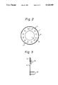
- FIG. 2 is a sectional view along line 2--2 of FIG. 1;
- FIG. 3 is a sectional view of a fin in FIG. 1, and
- FIG. 4 is a longitudinal sectional view of a continuous washing apparatus according to second embodiment of the present invention.
- the washing apparatus includes a long generally cylindrical washing tub 1.
- the washing tab 1 has an inlet 2 and an outlet 3 of washing objects W.
- the washing tub 1 is inclined so that the inlet 2 is lower and the outlet 3 is upper position.
- Transfer means is provided in the washing tub 1 to transfer the washing objects from the inlet region to the outlet region.
- the transfer means is formed by a screw assembly 4 which is rotatably mounted in the washing tub 1 and a drive means, not shown, to drive the screw assembly 4.
- the screw assembly 4 includes a band like fin 5 which is helically wound and extends longitudinally in the tub to form a central large opening 6.
- the screw assembly 4 includes shafts 7 and 8 which are secured with the both ends of the fin 5.
- the sahft 7 is rotatably supported by a bearing 9 which is mounted on a support frame 10 which forms upper end wall of the tub 1.
- the shaft 8 is connected with a drive shaft 11 which passes through and is rotatably supported by a lower end wall of the tab 1.
- the drive shaft 11 is connected with the drive means e.g. an electric motor through suitable transmission.
- connection between the shaft 7 and the bearing 9 and between the shaft 8 and the drive shaft 11 are taper connections. Such a taper connection allows easy assembly and disassembly without needing accurate realignment. By removing the support frame 10, the screw assembly 4 can be inserted and removed in and from the washing tub 1.
- the washing tub provides the washing means which includes, in the illustrated embodiment, cleaning liquid 12 stored in lower portion of the tub and air nozzles 13 to feed air in the cleaning liquid 12. Additional cleaning liquid nozzles 14 may be added. The additional nozzles 14 spray hot or cold water through a pipe which passes through central openings of the bearing 9 and the shaft 7 from outside.
- the fin 5 As shown in FIG. 2, large central opening 6 is formed to convey the washing objects of the height only corresponding to the width of the fin 5 and excessive objects pass rearward from the central opening 6 so that overloading of the fin is effectively prevented.
- the fin 5 itself has many small openings 17 to allow to pass cleaning liquid and debris from the openings 17 when the fin moves upward along the inclination of the tab 1.
- many small rods 18 pivotably mounted on the surface of the fin 5 to agitate or tumble the washing objects while conveying the objects.
- the bottom portion of the tab 1 has a reservoir 15 to store debris after washing.
- the reservoir 15 has a discharge pipe 16.
- washing objects W are fed from the inlet 2, and the objects are conveyed by the screw assembly 4 upwards from the inlet region to the outlet region.
- the washing objects are washed by the cleaning liquid and the washed objects are discharged from the outlet 3.
- FIG. 4 shows second embodiment of the present invention.
- the continuous washing apparatus includes a first washing apparatus A, a second washing apparatus B and a rinse and drying apparatus C.
- the first washing apparatus A is similar to that shown in FIG. 1.
- the second washing apparatus B is arranged adjacent to the first washing apparatus A and includes a generally semi-circular sectioned washing tub 20 in which a fin 5 similar with that shown in FIG. 1 is arranged.
- a drive shaft 21 of the fin 5 is driven by a suitable motor, not shown. Washing water is sprayed from opening of the stationary pipe shaft 23.
- One or more supersonic wave generators 22 are mounted at bottom plate of the washing tub 20.
- the rinse and drying apparatus C is arranged adjacent to the second washing apparatus B and includes a cylindrical drying tub 25 in which a fin 5, a reservoir 15 and a discharge pipe 16 which are similar with those shown in the first washing apparatus A are arranged and a drive shaft 26 of the fin 5 is driven by a motor, not shown.
- a stationary pipe 28 is mounted and through which hot air supplied from a hot air pipe 29 is injected.
- first washing objects W are fed from the inlet 1 of the first washing apparatus A and the fin 5 is rotated.
- the washing objects are washed by cleaning liquid which is agitated by the air supplied from the air nozzles 13 and are conveyed by the fin 5 generally for the height corresponding to the width of the fin 5 and excess objects over the height pass through the large opening 6 formed by the fin 5 and remain on the downstream side of the fin 5 so that the conveyed washing objects are limited to generally constant flow by the width of the fin 5.
- the washing objects are floated or tumbled by a liquid flow induced by air stream from the air nozzles 13.
- Washing objects change the attitude by rotation of the fin 5 to improve washing effect, and also, by many pivotably mounted rods 18 on the fin 5, washing objects reverse the attitude to further improve the washing effect.
- This feature is effective to wash planar objects such as dishes. Debris separate from the washing objects returns downwards through the many small openings 17 and clearance between the fin and the inner wall of the washing tub 1 to the reservoir 15 and is discharged through the discharge pipe 16. Washed objects are conveyed upwards by the fin 5 sequentially and are rinsed by hot or cold water from the nozzles 14 and are conveyed to the second washing apparatus B from the outlet 3.
- washing objects W are washed by the supersonic wave generator 22 and are conveyed to the rinse and drying apparatus C in which hot water from the hot water nozzles 27 at the bottom of the tub 25 assists drying of the objects, and then hot air from hot air nozzles 30 drys the washing objects.
- the washing apparatus includes the inclined cylindrical washing tub having the inlet for washing objects, the rotatable helical fin supported in the tub at both ends and the large central opening formed by the fin so that the advantages described below are attained.
- the illustrated second embodiment includes the first washing apparatus A, the second washing apparatus B and the rinse and drying apparatus C, whereas, the washing tub of the first washing apparatus A may be long enough to involve functions of the second washing apparatus B and/or the rinse and drying apparatus C so that one long apparatus can perform washing to drying processes.
Abstract
Description
Claims (4)
Applications Claiming Priority (2)
| Application Number | Priority Date | Filing Date | Title |
|---|---|---|---|
| JP63-246541 | 1988-09-30 | ||
| JP63246541A JPH0665395B2 (en) | 1988-09-30 | 1988-09-30 | Continuous cleaning device |
Publications (1)
| Publication Number | Publication Date |
|---|---|
| US5020555A true US5020555A (en) | 1991-06-04 |
Family
ID=17149944
Family Applications (1)
| Application Number | Title | Priority Date | Filing Date |
|---|---|---|---|
| US07/376,311 Expired - Fee Related US5020555A (en) | 1988-09-30 | 1989-07-06 | Continuous washing apparatus |
Country Status (3)
| Country | Link |
|---|---|
| US (1) | US5020555A (en) |
| JP (1) | JPH0665395B2 (en) |
| FR (1) | FR2637202B1 (en) |
Cited By (11)
| Publication number | Priority date | Publication date | Assignee | Title |
|---|---|---|---|---|
| US5119721A (en) * | 1990-08-27 | 1992-06-09 | Satake Engineering Co., Ltd. | Apparatus for producing washed rice |
| US5173122A (en) * | 1991-01-04 | 1992-12-22 | Tilby Sydney E | Apparatus for washing sugarcane billets |
| US5353822A (en) * | 1992-01-29 | 1994-10-11 | Restaurant Technology, Inc. | Apparatus and method for washing balls |
| WO1995019854A1 (en) * | 1994-01-21 | 1995-07-27 | Discovery Zone, Inc. | Apparatus and method for washing balls |
| US5439655A (en) * | 1992-06-19 | 1995-08-08 | Fedegari Autoclavi S.P.A. | Apparatus for washing and sterilizing rubber plugs or the like which may be used in pharmaceutical containers |
| US5858116A (en) * | 1996-11-19 | 1999-01-12 | Samsung Electronics Co., Ltd. | Bowl cleansing device having fruit and vegetable cleansing mode and fruit and vegetable cleansing method using the same |
| EP1018306A1 (en) * | 1998-12-28 | 2000-07-12 | Kibbutz Lotan Technology Center Ltd., Kibbutz Lotan, D.N. Chevel Eilot | Machine for prolonging the shelf-life of vegetables and fruits |
| US20030089386A1 (en) * | 2001-09-15 | 2003-05-15 | Alois Muller | Modular treatment plant having horizontal drum machines |
| US6923102B1 (en) * | 1999-06-29 | 2005-08-02 | Potato Processing Machinery Ab | Washing device |
| US20100146713A1 (en) * | 2008-11-21 | 2010-06-17 | Yoav Medan | Method and Apparatus for Washing Fabrics Using Focused Ultrasound |
| RU2787788C1 (en) * | 2022-01-11 | 2023-01-12 | Федеральное государственное бюджетное образовательное учреждение высшего образования "Иркутский государственный аграрный университет имени А.А. Ежевского" | Device for washing root crops |
Families Citing this family (2)
| Publication number | Priority date | Publication date | Assignee | Title |
|---|---|---|---|---|
| JPH06254515A (en) * | 1993-02-15 | 1994-09-13 | Nippon Guriisu Nitsupuru Kk | Article washing device and cage cylinder and fully automatic work processing system |
| FR2776542B1 (en) * | 1998-03-31 | 2004-06-11 | Suzuki Motor Co | ULTRASONIC CLEANING APPARATUS |
Citations (13)
| Publication number | Priority date | Publication date | Assignee | Title |
|---|---|---|---|---|
| US549097A (en) * | 1895-11-05 | Machine for cleaning and scalding tomatoes | ||
| US1530415A (en) * | 1923-05-24 | 1925-03-17 | William H Roussel | Egg-processing apparatus |
| US2314871A (en) * | 1939-08-12 | 1943-03-30 | Chisholm Ryder Co Inc | Apparatus for treating foodstuffs |
| US2555908A (en) * | 1949-04-28 | 1951-06-05 | Gen Mills Inc | Starch gluten separation |
| US2925821A (en) * | 1956-02-20 | 1960-02-23 | Michigan Foundry Supply Compan | Apparatus for treating metal borings |
| US3498839A (en) * | 1966-05-12 | 1970-03-03 | Leiner & Sons P | Washing apparatus and method |
| US3658072A (en) * | 1969-11-28 | 1972-04-25 | Vincent J Santucci | Apparatus for treating foodstuff |
| US4073301A (en) * | 1975-09-26 | 1978-02-14 | Huntington Alloys, Inc. | Liquid treatment of small articles |
| US4098225A (en) * | 1974-07-30 | 1978-07-04 | Maurice Norman | Environmental, small-part continuous washing apparatus |
| DE2806126A1 (en) * | 1978-02-14 | 1979-08-16 | Friedrich Epple | Machine for washing small mass produced articles - directs jets of cleaning fluid on articles inside perforated tube |
| JPS5940437A (en) * | 1982-08-27 | 1984-03-06 | Toshiba Corp | Production process for cathode-ray tube |
| US4611612A (en) * | 1984-05-01 | 1986-09-16 | Chicagoland Processing Corp. | Apparatus for continuously treating solids with liquids |
| SU1298151A1 (en) * | 1985-04-03 | 1987-03-23 | Симферопольский Филиал Научно-Производственного Объединения "Агроприбор" | Screw conveyer for transporting loose materials |
Family Cites Families (13)
| Publication number | Priority date | Publication date | Assignee | Title |
|---|---|---|---|---|
| DE1078406B (en) * | 1957-08-06 | 1960-03-24 | Siemens Ag | Device for cleaning metal and non-metal parts under the action of ultrasonic vibrations |
| GB1035852A (en) * | 1964-01-17 | 1966-07-13 | Sheet Metal Shapes Ltd | Washing machines, particularly for cleaning machine parts |
| JPS4421451Y1 (en) * | 1965-06-23 | 1969-09-11 | ||
| JPS459563Y1 (en) * | 1965-07-14 | 1970-05-04 | ||
| US3544369A (en) * | 1967-12-26 | 1970-12-01 | Fmc Corp | Method for the cleaning of metal waste and the recovery of oil therefrom |
| DE2804729C2 (en) * | 1978-02-01 | 1985-03-07 | Buckau-Walther AG, 4048 Grevenbroich | Device for washing and drying bulk goods, in particular shredded plastic waste |
| JPS56102649U (en) * | 1980-01-10 | 1981-08-12 | ||
| JPS5746024U (en) * | 1980-08-25 | 1982-03-13 | ||
| JPS57136951A (en) * | 1981-02-18 | 1982-08-24 | Kokudo Tetsukou Kk | Continuous type granular body washing machine |
| JPS59196790A (en) * | 1983-04-22 | 1984-11-08 | ジャパン・フイ−ルド株式会社 | Method and apparatus for washing long article |
| JPH0666261B2 (en) * | 1984-07-03 | 1994-08-24 | 日本電気株式会社 | Thin film formation method |
| JPS63162084A (en) * | 1986-12-26 | 1988-07-05 | ジヤパン・フイ−ルド株式会社 | Washer |
| JPH045456Y2 (en) * | 1987-01-24 | 1992-02-17 |
-
1988
- 1988-09-30 JP JP63246541A patent/JPH0665395B2/en not_active Expired - Lifetime
-
1989
- 1989-07-06 US US07/376,311 patent/US5020555A/en not_active Expired - Fee Related
- 1989-07-20 FR FR8909801A patent/FR2637202B1/en not_active Expired - Fee Related
Patent Citations (13)
| Publication number | Priority date | Publication date | Assignee | Title |
|---|---|---|---|---|
| US549097A (en) * | 1895-11-05 | Machine for cleaning and scalding tomatoes | ||
| US1530415A (en) * | 1923-05-24 | 1925-03-17 | William H Roussel | Egg-processing apparatus |
| US2314871A (en) * | 1939-08-12 | 1943-03-30 | Chisholm Ryder Co Inc | Apparatus for treating foodstuffs |
| US2555908A (en) * | 1949-04-28 | 1951-06-05 | Gen Mills Inc | Starch gluten separation |
| US2925821A (en) * | 1956-02-20 | 1960-02-23 | Michigan Foundry Supply Compan | Apparatus for treating metal borings |
| US3498839A (en) * | 1966-05-12 | 1970-03-03 | Leiner & Sons P | Washing apparatus and method |
| US3658072A (en) * | 1969-11-28 | 1972-04-25 | Vincent J Santucci | Apparatus for treating foodstuff |
| US4098225A (en) * | 1974-07-30 | 1978-07-04 | Maurice Norman | Environmental, small-part continuous washing apparatus |
| US4073301A (en) * | 1975-09-26 | 1978-02-14 | Huntington Alloys, Inc. | Liquid treatment of small articles |
| DE2806126A1 (en) * | 1978-02-14 | 1979-08-16 | Friedrich Epple | Machine for washing small mass produced articles - directs jets of cleaning fluid on articles inside perforated tube |
| JPS5940437A (en) * | 1982-08-27 | 1984-03-06 | Toshiba Corp | Production process for cathode-ray tube |
| US4611612A (en) * | 1984-05-01 | 1986-09-16 | Chicagoland Processing Corp. | Apparatus for continuously treating solids with liquids |
| SU1298151A1 (en) * | 1985-04-03 | 1987-03-23 | Симферопольский Филиал Научно-Производственного Объединения "Агроприбор" | Screw conveyer for transporting loose materials |
Cited By (17)
| Publication number | Priority date | Publication date | Assignee | Title |
|---|---|---|---|---|
| US5119721A (en) * | 1990-08-27 | 1992-06-09 | Satake Engineering Co., Ltd. | Apparatus for producing washed rice |
| US5173122A (en) * | 1991-01-04 | 1992-12-22 | Tilby Sydney E | Apparatus for washing sugarcane billets |
| US5542440A (en) * | 1992-01-29 | 1996-08-06 | Discovery Zone, Inc | Apparatus and method for washing balls |
| US5353822A (en) * | 1992-01-29 | 1994-10-11 | Restaurant Technology, Inc. | Apparatus and method for washing balls |
| US5546967A (en) * | 1992-01-29 | 1996-08-20 | Discovery Zone, Inc. | Apparatus and method for washing balls |
| US5482565A (en) * | 1992-01-29 | 1996-01-09 | Discovery Zone, Inc. | Method for washing balls |
| US5499641A (en) * | 1992-01-29 | 1996-03-19 | Discovery Zone, Inc. | Apparatus and method for washing balls |
| US5439655A (en) * | 1992-06-19 | 1995-08-08 | Fedegari Autoclavi S.P.A. | Apparatus for washing and sterilizing rubber plugs or the like which may be used in pharmaceutical containers |
| WO1995019854A1 (en) * | 1994-01-21 | 1995-07-27 | Discovery Zone, Inc. | Apparatus and method for washing balls |
| US5858116A (en) * | 1996-11-19 | 1999-01-12 | Samsung Electronics Co., Ltd. | Bowl cleansing device having fruit and vegetable cleansing mode and fruit and vegetable cleansing method using the same |
| EP1018306A1 (en) * | 1998-12-28 | 2000-07-12 | Kibbutz Lotan Technology Center Ltd., Kibbutz Lotan, D.N. Chevel Eilot | Machine for prolonging the shelf-life of vegetables and fruits |
| US6923102B1 (en) * | 1999-06-29 | 2005-08-02 | Potato Processing Machinery Ab | Washing device |
| US20030089386A1 (en) * | 2001-09-15 | 2003-05-15 | Alois Muller | Modular treatment plant having horizontal drum machines |
| US7066187B2 (en) * | 2001-09-15 | 2006-06-27 | Mueller Alois | Modular treatment plant having horizontal drum machines |
| US20060236728A1 (en) * | 2001-09-15 | 2006-10-26 | Mueller Alois | Modular treatment plant having horizontal drum machines |
| US20100146713A1 (en) * | 2008-11-21 | 2010-06-17 | Yoav Medan | Method and Apparatus for Washing Fabrics Using Focused Ultrasound |
| RU2787788C1 (en) * | 2022-01-11 | 2023-01-12 | Федеральное государственное бюджетное образовательное учреждение высшего образования "Иркутский государственный аграрный университет имени А.А. Ежевского" | Device for washing root crops |
Also Published As
| Publication number | Publication date |
|---|---|
| FR2637202A1 (en) | 1990-04-06 |
| FR2637202B1 (en) | 1994-11-04 |
| JPH0665395B2 (en) | 1994-08-24 |
| JPH0295486A (en) | 1990-04-06 |
Similar Documents
| Publication | Publication Date | Title |
|---|---|---|
| US5020555A (en) | Continuous washing apparatus | |
| US5549759A (en) | Method and apparatus for cleaning cylindrical components which are transversely rotated in a drum during liquid treatment | |
| KR102026687B1 (en) | Pepper Foreign Material Washer | |
| US5000205A (en) | Method of pre-washing and after-washing tuberous products of peeling thereof and an apparatus for performing the method | |
| US4719933A (en) | Machine for washing particulate workpieces | |
| JP4224770B2 (en) | Grain washer and dryer connected to it | |
| US5148566A (en) | Continuous washing apparatus | |
| US5331702A (en) | Golf ball washing apparatus and method | |
| SE468787B (en) | DEVICE FOR TREATMENT OF CIRCULAR GOODS, eg WASHING OF GOLF BALLS | |
| US3056414A (en) | Article washing machine | |
| KR100401953B1 (en) | dry type rice not wash polished rice device | |
| CN208850617U (en) | A kind of potato peeler structure and peeling machine | |
| US5862821A (en) | Apparatus for washing leafy plant products | |
| US1215596A (en) | Fruit-washer. | |
| JPH05199975A (en) | Continuous cleaner | |
| CN208494405U (en) | A kind of cereal dedusting baking grinding all-in-one machine | |
| WO1995009696A1 (en) | A method, device and composition in material spraying | |
| KR920001664B1 (en) | Washing devices | |
| USRE25421E (en) | nolte | |
| KR960014857B1 (en) | Apparatus for washing seaweeds | |
| KR200357288Y1 (en) | Drying machine for eating plate and automatic washer using the same | |
| KR102474535B1 (en) | Grain washer | |
| CN214638521U (en) | Cylinder washs air dryer | |
| CN217487582U (en) | Automatic nut cleaning machine | |
| JP2984785B2 (en) | Centrifugal separation type juicer and method for cleaning the juicer |
Legal Events
| Date | Code | Title | Description |
|---|---|---|---|
| AS | Assignment |
Owner name: NARUHISA NISHIBAYASHI, 408-290, KANAGASAKU, MATSUD Free format text: ASSIGNMENT OF ASSIGNORS INTEREST.;ASSIGNOR:NISHIBAYASHI, SEITARO;REEL/FRAME:005099/0517 Effective date: 19890626 |
|
| FEPP | Fee payment procedure |
Free format text: PAT HLDR NO LONGER CLAIMS SMALL ENT STAT AS INDIV INVENTOR (ORIGINAL EVENT CODE: LSM1); ENTITY STATUS OF PATENT OWNER: LARGE ENTITY Free format text: PAYOR NUMBER ASSIGNED (ORIGINAL EVENT CODE: ASPN); ENTITY STATUS OF PATENT OWNER: LARGE ENTITY |
|
| FPAY | Fee payment |
Year of fee payment: 4 |
|
| REMI | Maintenance fee reminder mailed | ||
| LAPS | Lapse for failure to pay maintenance fees | ||
| FP | Lapsed due to failure to pay maintenance fee |
Effective date: 19990604 |
|
| STCH | Information on status: patent discontinuation |
Free format text: PATENT EXPIRED DUE TO NONPAYMENT OF MAINTENANCE FEES UNDER 37 CFR 1.362 |