US4984330A - Nozzle assembly for a vacuum device - Google Patents
Nozzle assembly for a vacuum device Download PDFInfo
- Publication number
- US4984330A US4984330A US07/385,966 US38596689A US4984330A US 4984330 A US4984330 A US 4984330A US 38596689 A US38596689 A US 38596689A US 4984330 A US4984330 A US 4984330A
- Authority
- US
- United States
- Prior art keywords
- inlet opening
- nozzle
- generally cylindrical
- vacuum conduit
- coupling section
- Prior art date
- Legal status (The legal status is an assumption and is not a legal conclusion. Google has not performed a legal analysis and makes no representation as to the accuracy of the status listed.)
- Expired - Lifetime
Links
Images


Classifications
-
- F—MECHANICAL ENGINEERING; LIGHTING; HEATING; WEAPONS; BLASTING
- F16—ENGINEERING ELEMENTS AND UNITS; GENERAL MEASURES FOR PRODUCING AND MAINTAINING EFFECTIVE FUNCTIONING OF MACHINES OR INSTALLATIONS; THERMAL INSULATION IN GENERAL
- F16L—PIPES; JOINTS OR FITTINGS FOR PIPES; SUPPORTS FOR PIPES, CABLES OR PROTECTIVE TUBING; MEANS FOR THERMAL INSULATION IN GENERAL
- F16L37/00—Couplings of the quick-acting type
- F16L37/50—Couplings of the quick-acting type adjustable; allowing movement of the parts joined
- F16L37/53—Couplings of the quick-acting type adjustable; allowing movement of the parts joined allowing adjustment or movement only about the axis of one pipe
-
- A—HUMAN NECESSITIES
- A47—FURNITURE; DOMESTIC ARTICLES OR APPLIANCES; COFFEE MILLS; SPICE MILLS; SUCTION CLEANERS IN GENERAL
- A47L—DOMESTIC WASHING OR CLEANING; SUCTION CLEANERS IN GENERAL
- A47L9/00—Details or accessories of suction cleaners, e.g. mechanical means for controlling the suction or for effecting pulsating action; Storing devices specially adapted to suction cleaners or parts thereof; Carrying-vehicles specially adapted for suction cleaners
- A47L9/02—Nozzles
-
- A—HUMAN NECESSITIES
- A47—FURNITURE; DOMESTIC ARTICLES OR APPLIANCES; COFFEE MILLS; SPICE MILLS; SUCTION CLEANERS IN GENERAL
- A47L—DOMESTIC WASHING OR CLEANING; SUCTION CLEANERS IN GENERAL
- A47L9/00—Details or accessories of suction cleaners, e.g. mechanical means for controlling the suction or for effecting pulsating action; Storing devices specially adapted to suction cleaners or parts thereof; Carrying-vehicles specially adapted for suction cleaners
- A47L9/24—Hoses or pipes; Hose or pipe couplings
- A47L9/242—Hose or pipe couplings
Definitions
- the present invention relates to a nozzle assembly for a vacuum device such as a vacuum cleaner, and more particularly to an arrangement for attachment of a rigid vacuum conduit to a nozzle.
- Vacuum devices such as vacuum cleaners typically include a nozzle to which a flexible vacuum hose is attached.
- a rigid vacuum conduit is typically used as an intermediate connection between the flexible vacuum hose and the nozzle. It is often desirable that a high degree of rotational freedom exist between the rigid vacuum conduit and the nozzle to permit the nozzle to rotate as necessary over surfaces of changing contour.
- vacuum efficiency requires that the coupling between the rigid vacuum conduit and the nozzle be reasonably airtight. It would, thus, be desirable to provide a nozzle assembly achieving a desirable balance between rotational freedom of a nozzle relative to a rigid vacuum conduit, and the airtightness of the connection between the vacuum conduit and the nozzle.
- a further object of the invention is to provide an arrangement for coupling between a rigid vacuum conduit and a nozzle for a vacuum device wherein the arrangement is resistant to jamming due to dirt particles entrapped in the connection region.
- a further object of the invention is to provide an arrangement for coupling between a rigid vacuum conduit and a nozzle of a vacuum device in which a high degree of rotational freedom is maintained between the rigid conduit and the nozzle where the rigid conduit comprises metallic material.
- a nozzle assembly for a vacuum device in accordance with one version of the invention includes a nozzle and a suction conduit.
- the nozzle has an inlet opening of generally cylindrical shape.
- the suction conduit has a coupling section of generally cylindrical shape for insertion into the inlet opening.
- the adjacent portions of the coupling section and the inlet opening define an interface region.
- the interface region is provided with a plurality of spaced openings for receiving and harmlessly containing debris that otherwise would tend to jam the rigid vacuum conduit in fixed relation to the nozzle.
- a nozzle assembly for a vacuum device comprises a nozzle with an inlet opening of generally cylindrical shape, and a rigid suction conduit having a coupling section of generally cylindrical shape for insertion into the inlet opening.
- the suction conduit includes an annular band encircling a substantial extent of the coupling section and comprising nonmetallic material.
- the annular band may comprise a pair of half-round sections.
- the suction conduit includes a collar around the circumference of the coupling section, providing a stop against movement of the annular band.
- FIG. 1 is a rear view of a nozzle assembly in accordance with the invention, and is partially in cross-section.
- FIG. 2 is detail view of the nozzle assembly of FIG. 1 illustrating how a rigid vacuum conduit is rotated in an inlet opening of the nozzle for locking the conduit to the nozzle.
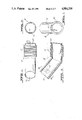
- FIG. 3 is cross-sectional view taken at line III--III in FIG. 4 and illustrating a rigid vacuum conduit in accordance with the invention.
- FIG. 4 is an upper plan view of the rigid vacuum conduit of FIG. 3.
- FIG. 5 is a cross-sectional view taken at line V--V in FIG. 1 and illustrating a coupling arrangement between the rigid vacuum conduit of FIGS. 3 and 4 and the nozzle of FIG. 1.
- FIG. 6 is a cross-sectional view of the rigid vacuum conduit of FIG. 3 and is taken at lines VI--VI thereof.
- FIG. 7 is an end plan view of the rigid vacuum conduit of FIG. 4 as viewed from the right-hand side of FIG. 4.
- FIG. 8 is a cross-sectional view taken at line VIII--VIII in FIG. 9 and illustrating a rigid vacuum conduit in accordance with a further embodiment of the invention.
- FIG. 9 is an upper plan view of the rigid vacuum conduit of FIG. 8.
- FIG. 10 is an end view of a pair of annular band sections that together are used to encircle a portion of the rigid vacuum conduit of FIGS. 8 and 9.
- FIG. 11 is an end plan view of the rigid vacuum conduit of FIG. 9 as viewed from the right-hand side of FIG. 9.
- FIG. 12 is a cross-sectional view taken at lines XII--XII in FIG. 1 and illustrating a coupling arrangement between the rigid vacuum conduit of FIGS. 8 and 9 and the nozzle of FIG. 1.
- FIG. 13 is an upper plane view of a rigid vacuum conduit like the conduit illustrated in FIG. 4, but with spiral grooves.
- FIG. 1 illustrates a nozzle 10 such as is typically used in a vacuum cleaner.
- the nozzle may include an auxiliary attachment such as a squeegee or brush 12, located rearwardly of a suction channel (not shown) extending from the left to the right of the illustrated nozzle.
- the squeegee o brush 12 may be attached to the frame of nozzle 10 by the use of projections 12a and 12b extending upwardly respectively through apertures 14a and 14b in the nozzle frame.
- a rigid suction conduit 16 is schematically illustrated in FIG. 1 and described in detail below. Vacuum conduit 16 is adapted to be received within an inlet opening 18 in nozzle 10.
- a retaining ring 20 on vacuum conduit 16 is adapted to be received through a gap 22 in a cooperating retaining ring 24 mounted on the nozzle.
- retaining ring 20 of vacuum conduit 16 is shown extending through gap 22 in retaining ring 24. Thereafter, vacuum conduit 16 is rotated clockwise or counterclockwise as indicated by double-headed arrow 26. Accordingly, retaining ring 20 is secured behind retaining ring 24 of the nozzle in normal usage when the exterior portion of rigid vacuum conduit 16 is rotated upwardly, as shown in FIG. 1, for example.
- FIGS. 3 through 7 illustrate various features of a vacuum conduit 16' in accordance with a first embodiment of the invention.
- FIGS. 3 and 4 illustrate a coupling section 30 included in conduit 16'.
- Coupling section 30 is generally cylindrical in shape. It is preferred that coupling section 30 taper slightly from left to right as illustrated in FIGS. 3 and 4, or from without to within in inlet opening 18 (FIG. 1) of nozzle 10.
- Inlet portion 18 is also preferred to be generally cylindrical in shape and to have a cooperating taper in the same direction as does coupling section 30 so that a reasonably tight fit can be maintained between the vacuum conduit and the nozzle of FIG. 1.
- coupling section 30 comprises a plurality of annular grooves encircling the coupling section and opening outwardly.
- Grooves 32 may be spaced side-by-side as illustrated or may be in the form of spiral grooves 32' (FIG. 13), for example.
- the provision of grooves 32 in coupling section 30 reduces the amount of material required to implement vacuum conduit 16'. Additional benefits realized by inclusion of grooves 32 in coupling section 30 are now discussed with reference to FIG. 5.
- grooves 32 can be seen to reduce the surface area of contact between coupling section 30 and inlet opening wall 18' of nozzle 10. This reduces the friction load between the vacuum conduit and the nozzle so that the vacuum conduit can rotate more freely within inlet opening 18 during use.
- the provision of grooves 32 furthermore, provides space for dirt particles, which may accumulate between coupling section 30 and inlet opening wall 18', to be deposited into the grooves. In this manner, the likelihood of jamming of vacuum conduit 16 in inlet opening 18 is reduced. Openings of different configurations than grooves 32 could be provided to fulfill the foregoing functions.
- interface region 34 comprising the adjacent portions of coupling section 30 and input opening wall 18', could be provided with openings, which could be solely in the wall, or partially in the wall and partially in coupling section 30.
- FIG. 5 additionally illustrates a vacuum conduit 36 within nozzle 10 which, in the illustrated device, has a downwardly extending opening as is typical of vacuum cleaner devices.
- FIGS. 3 and 6 illustrate an aperture 40 in the side wall of vacuum conduit 16' remote from coupling section 30.
- Aperture 40 is adapted to receive a projection from a coupling section of a vacuum hose, not illustrated herein, of conventional construction.
- Aperture 40 is preferably recessed to a flat face 42 of vacuum conduit 16'.
- Retaining ring 20' is preferably an arcuate segment of about 40° or 50°, while the corresponding gap 22 (FIG. 1) in retaining ring 24 of the nozzle is several degrees greater in arcuate extent so as to be able to readily receive retaining ring 20' therethrough.
- Retaining ring 20' could, however, be modified to occupy a greater arcuate extent if desired.
- FIGS. 8-12 illustrate a further vacuum conduit 16" in accordance with another version of the invention.
- vacuum conduit 16" can be seen to include a coupling section 50 of generally cylindrical configuration.
- an annular band 52 which preferably is formed of two sections 52a and 52b. Together, annular band sections 52a and 52b surround at least a substantial portion of the circumference of coupling section 50.
- FIGS. 8 and 9 are preferably implemented with vacuum conduit 16" comprising a metallic or high friction material, while annular band 52 comprises a nonmetallic or low friction material.
- the provision of annular band 52 then assures free rotational movement of vacuum conduit 16" within input opening 18 (FIG. 1) of nozzle 10.
- coupling section 50 preferably includes an outward projection 54.
- annular band portion 52a Cooperating with outward projection 54 is an aperture 56, preferably contained in annular band portion 52a.
- a collar 58 can be seen included within coupling section 50 of vacuum conduit 16" and located outwardly of annular band 52 with respect to nozzle 10 (FIG. 1). Collar 58 provides a stop against outward movement of annular band 52.
- coupling section 50 is preferably tapered slightly from left to right as illustrated in FIGS. 8 and 9.
- inlet opening 18 (FIG. 1) of nozzle 10 is preferably tapered in the same manner.
- Vacuum conduit 16" of FIG. 8 preferably includes an aperture 60 extending inwardly from a flat face 62 in the same manner as aperture 40 and face 42 described above in connection with FIG. 3.
- vacuum conduit 16" may include a retaining ring 20" of substantially similar function as retaining ring 20' described above in connection with FIGS. 3 and 7.
- FIG. 12 illustrates the inserted position of vacuum conduit 16" in inlet opening 18 of nozzle 10. It can be seen that annular bands 52a and 52b provide the major bearing surface against inlet opening wall 18' of the nozzle. Accordingly, non-jamming rotational movement of vacuum conduit 16" within inlet opening 18 is achieved.
- a metal vacuum conduit can be accommodated by the invention.
- One embodiment is particularly resistant to jamming of rotational movement between the vacuum conduit and the nozzle in the presence of dirt particles in the region of attachment.
Landscapes
- Engineering & Computer Science (AREA)
- Mechanical Engineering (AREA)
- General Engineering & Computer Science (AREA)
- Electric Vacuum Cleaner (AREA)
Abstract
Description
Claims (3)
Priority Applications (2)
| Application Number | Priority Date | Filing Date | Title |
|---|---|---|---|
| US07/385,966 US4984330A (en) | 1986-12-08 | 1989-07-27 | Nozzle assembly for a vacuum device |
| US07/628,708 US5079796A (en) | 1986-12-08 | 1990-12-17 | Nozzle assembly for a vacuum device |
Applications Claiming Priority (3)
| Application Number | Priority Date | Filing Date | Title |
|---|---|---|---|
| US93885086A | 1986-12-08 | 1986-12-08 | |
| US17114588A | 1988-03-16 | 1988-03-16 | |
| US07/385,966 US4984330A (en) | 1986-12-08 | 1989-07-27 | Nozzle assembly for a vacuum device |
Related Parent Applications (1)
| Application Number | Title | Priority Date | Filing Date |
|---|---|---|---|
| US17114588A Continuation | 1986-12-08 | 1988-03-16 |
Related Child Applications (1)
| Application Number | Title | Priority Date | Filing Date |
|---|---|---|---|
| US07/628,708 Division US5079796A (en) | 1986-12-08 | 1990-12-17 | Nozzle assembly for a vacuum device |
Publications (1)
| Publication Number | Publication Date |
|---|---|
| US4984330A true US4984330A (en) | 1991-01-15 |
Family
ID=27389932
Family Applications (1)
| Application Number | Title | Priority Date | Filing Date |
|---|---|---|---|
| US07/385,966 Expired - Lifetime US4984330A (en) | 1986-12-08 | 1989-07-27 | Nozzle assembly for a vacuum device |
Country Status (1)
| Country | Link |
|---|---|
| US (1) | US4984330A (en) |
Cited By (3)
| Publication number | Priority date | Publication date | Assignee | Title |
|---|---|---|---|---|
| US5967563A (en) * | 1995-10-03 | 1999-10-19 | Wci Canada, Inc. | Quick release for a vacuum cleaner powerhead |
| USD439711S1 (en) | 2000-04-27 | 2001-03-27 | Shop Vac Corporation | Nozzle |
| US20240401729A1 (en) * | 2022-08-25 | 2024-12-05 | Todd Sixtoes | Swivel hose connection device |
Citations (25)
| Publication number | Priority date | Publication date | Assignee | Title |
|---|---|---|---|---|
| US607105A (en) * | 1898-07-12 | Brush | ||
| GB482347A (en) * | 1936-09-26 | 1938-03-28 | Sidney Herbert Smith | Improvements relating to extension tubes of vacuum cleaners |
| GB637468A (en) * | 1946-08-15 | 1950-05-17 | Hoover Ltd | Improvements relating to spigot and socket joints |
| GB659656A (en) * | 1948-06-10 | 1951-10-24 | Hoover Ltd | Improvements relating to cleaning tools for suction cleaners |
| US2586145A (en) * | 1948-05-21 | 1952-02-19 | Breuer Electric Mfg Company | Draft applying tool for portable motor-blower units |
| GB963910A (en) * | 1960-01-18 | 1964-07-15 | Albert Stulz | Improvements in and relating to pipe joints |
| GB1025096A (en) * | 1962-05-24 | 1966-04-06 | Le Super | Tube for vacuum cleaners |
| NL6513575A (en) * | 1964-12-18 | 1966-06-20 | ||
| US3286295A (en) * | 1964-12-04 | 1966-11-22 | Westinghouse Electric Corp | Vacuum cleaner nozzle |
| US3306634A (en) * | 1963-02-07 | 1967-02-28 | Pul Vac Inc | Articulate joint |
| US3309113A (en) * | 1966-02-24 | 1967-03-14 | Hoover Co | Coupling for suction cleaner attachments |
| US3314039A (en) * | 1965-03-09 | 1967-04-11 | Dayco Corp | Vacuum cleaner connector |
| GB1215980A (en) * | 1968-09-11 | 1970-12-16 | Dunlop Co Ltd | Improvements in hose end fittings |
| GB1315750A (en) * | 1970-02-06 | 1973-05-02 | Wessel H | Suction nozzles for use with suction cleaners |
| US3739422A (en) * | 1971-09-28 | 1973-06-19 | Whirlpool Co | Shag rug cleaning tool for use with vacuum cleaners |
| GB1362096A (en) * | 1971-09-13 | 1974-07-30 | Electrolux Ltd | Method of manufacturing hoses and hose made according to the method |
| US3832753A (en) * | 1972-09-12 | 1974-09-03 | Whirlpool Co | Vacuum cleaner structure |
| US3869751A (en) * | 1973-11-16 | 1975-03-11 | Hoover Co | Interlocked conversion for a convertible cleaner |
| GB1506610A (en) * | 1975-11-04 | 1978-04-05 | Wessel H | Sealing elements |
| WO1981000748A1 (en) * | 1979-09-17 | 1981-03-19 | Plastiflex Co Int | Self-sealing vacuum hose swivel fitting |
| US4449737A (en) * | 1982-04-21 | 1984-05-22 | The Hoover Company | Hose coupler locking arrangement |
| GB2140673A (en) * | 1983-05-30 | 1984-12-05 | Hans Wessel | Vacuum cleaner nozzles |
| US4558889A (en) * | 1984-10-26 | 1985-12-17 | Action Technology | Aquatic vacuum hose swivel cuff |
| US4564972A (en) * | 1983-05-17 | 1986-01-21 | Etablissements Georges Olivier | Roller or skid type vacuum cleaner nozzle attachment |
| US4625998A (en) * | 1984-04-02 | 1986-12-02 | Draudt Donald A | Swivel hose couplings |
-
1989
- 1989-07-27 US US07/385,966 patent/US4984330A/en not_active Expired - Lifetime
Patent Citations (25)
| Publication number | Priority date | Publication date | Assignee | Title |
|---|---|---|---|---|
| US607105A (en) * | 1898-07-12 | Brush | ||
| GB482347A (en) * | 1936-09-26 | 1938-03-28 | Sidney Herbert Smith | Improvements relating to extension tubes of vacuum cleaners |
| GB637468A (en) * | 1946-08-15 | 1950-05-17 | Hoover Ltd | Improvements relating to spigot and socket joints |
| US2586145A (en) * | 1948-05-21 | 1952-02-19 | Breuer Electric Mfg Company | Draft applying tool for portable motor-blower units |
| GB659656A (en) * | 1948-06-10 | 1951-10-24 | Hoover Ltd | Improvements relating to cleaning tools for suction cleaners |
| GB963910A (en) * | 1960-01-18 | 1964-07-15 | Albert Stulz | Improvements in and relating to pipe joints |
| GB1025096A (en) * | 1962-05-24 | 1966-04-06 | Le Super | Tube for vacuum cleaners |
| US3306634A (en) * | 1963-02-07 | 1967-02-28 | Pul Vac Inc | Articulate joint |
| US3286295A (en) * | 1964-12-04 | 1966-11-22 | Westinghouse Electric Corp | Vacuum cleaner nozzle |
| NL6513575A (en) * | 1964-12-18 | 1966-06-20 | ||
| US3314039A (en) * | 1965-03-09 | 1967-04-11 | Dayco Corp | Vacuum cleaner connector |
| US3309113A (en) * | 1966-02-24 | 1967-03-14 | Hoover Co | Coupling for suction cleaner attachments |
| GB1215980A (en) * | 1968-09-11 | 1970-12-16 | Dunlop Co Ltd | Improvements in hose end fittings |
| GB1315750A (en) * | 1970-02-06 | 1973-05-02 | Wessel H | Suction nozzles for use with suction cleaners |
| GB1362096A (en) * | 1971-09-13 | 1974-07-30 | Electrolux Ltd | Method of manufacturing hoses and hose made according to the method |
| US3739422A (en) * | 1971-09-28 | 1973-06-19 | Whirlpool Co | Shag rug cleaning tool for use with vacuum cleaners |
| US3832753A (en) * | 1972-09-12 | 1974-09-03 | Whirlpool Co | Vacuum cleaner structure |
| US3869751A (en) * | 1973-11-16 | 1975-03-11 | Hoover Co | Interlocked conversion for a convertible cleaner |
| GB1506610A (en) * | 1975-11-04 | 1978-04-05 | Wessel H | Sealing elements |
| WO1981000748A1 (en) * | 1979-09-17 | 1981-03-19 | Plastiflex Co Int | Self-sealing vacuum hose swivel fitting |
| US4449737A (en) * | 1982-04-21 | 1984-05-22 | The Hoover Company | Hose coupler locking arrangement |
| US4564972A (en) * | 1983-05-17 | 1986-01-21 | Etablissements Georges Olivier | Roller or skid type vacuum cleaner nozzle attachment |
| GB2140673A (en) * | 1983-05-30 | 1984-12-05 | Hans Wessel | Vacuum cleaner nozzles |
| US4625998A (en) * | 1984-04-02 | 1986-12-02 | Draudt Donald A | Swivel hose couplings |
| US4558889A (en) * | 1984-10-26 | 1985-12-17 | Action Technology | Aquatic vacuum hose swivel cuff |
Cited By (4)
| Publication number | Priority date | Publication date | Assignee | Title |
|---|---|---|---|---|
| US5967563A (en) * | 1995-10-03 | 1999-10-19 | Wci Canada, Inc. | Quick release for a vacuum cleaner powerhead |
| USD439711S1 (en) | 2000-04-27 | 2001-03-27 | Shop Vac Corporation | Nozzle |
| US20240401729A1 (en) * | 2022-08-25 | 2024-12-05 | Todd Sixtoes | Swivel hose connection device |
| US12449076B2 (en) * | 2022-08-25 | 2025-10-21 | Todd Sixtoes | Swivel hose connection device |
Similar Documents
| Publication | Publication Date | Title |
|---|---|---|
| US5031266A (en) | Vacuum cleaner wand seal | |
| US4941689A (en) | Coupling device for vacuum cleaner | |
| EP0145781B1 (en) | Means for sealing the gap between two axially displaceable sealing surfaces | |
| US4477109A (en) | Connector for hoses and the like | |
| EP0824928A3 (en) | Tracheostomy tube assemblies | |
| EP1000579A3 (en) | Vacuum cleaner having a dual filter assembly | |
| SK283617B6 (en) | Suction tube connection plug | |
| US5079796A (en) | Nozzle assembly for a vacuum device | |
| US4984330A (en) | Nozzle assembly for a vacuum device | |
| US4747179A (en) | Nozzle with improved coupling for a vacuum device | |
| CA1302669C (en) | Nozzle assembly for a vacuum device | |
| EP0827238A3 (en) | Self-aligning and locking shielded connector | |
| JPH09322361A (en) | Grommet | |
| US7578413B2 (en) | Single-piece sealing cover | |
| US5676313A (en) | Regulating cap with protection covers | |
| EP1039206A3 (en) | Hose connector | |
| HU9903847D0 (en) | Telescopic suction of vacuum cleaner | |
| JPH043160Y2 (en) | ||
| JP2000065257A (en) | hose | |
| JPH06159566A (en) | Coming-off preventive pipe joint | |
| KR950006709B1 (en) | Extension pipe of vacuum cleaner | |
| JPH06159565A (en) | Coming-off preventive pipe joint | |
| KR950000269Y1 (en) | Extension tube of vacuum cleaner | |
| JPH04277170A (en) | Cord reel | |
| JPH0435669Y2 (en) |
Legal Events
| Date | Code | Title | Description |
|---|---|---|---|
| AS | Assignment |
Owner name: FIRST UNION NATIONAL BANK OF NORTH CAROLINA, NORTH Free format text: ASSIGNMENT OF ASSIGNORS INTEREST.;ASSIGNOR:SHOP VAC CORPORATION;REEL/FRAME:005321/0501 Effective date: 19900530 |
|
| STCF | Information on status: patent grant |
Free format text: PATENTED CASE |
|
| FEPP | Fee payment procedure |
Free format text: PAYOR NUMBER ASSIGNED (ORIGINAL EVENT CODE: ASPN); ENTITY STATUS OF PATENT OWNER: LARGE ENTITY |
|
| FPAY | Fee payment |
Year of fee payment: 4 |
|
| AS | Assignment |
Owner name: SHOP VAC CORPORATION, PENNSYLVANIA Free format text: RELEASE OF PATENT COLLATERAL;ASSIGNOR:FIRST UNION NATIONAL BANK OF NORTH CAROLINA;REEL/FRAME:008274/0624 Effective date: 19960930 |
|
| FPAY | Fee payment |
Year of fee payment: 8 |
|
| AS | Assignment |
Owner name: LEHMAN COMMERCIAL PAPER INC., AS ADMINISTRATIVE AG Free format text: SECURITY AGREEMENT;ASSIGNOR:SHOP VAC CORPORATION;REEL/FRAME:010231/0454 Effective date: 19990708 |
|
| FPAY | Fee payment |
Year of fee payment: 12 |
|
| AS | Assignment |
Owner name: WACHOVIA BANK, N.A., AS ADMINISTRATIVE AGENT, NORT Free format text: NOTICE OF GRANT OF SECURITY INTEREST;ASSIGNOR:SHOP VAC CORPORATION;REEL/FRAME:013727/0608 Effective date: 20021217 |
|
| AS | Assignment |
Owner name: WACHOVIA BANK, NATIONAL ASSOCIATION, AS ADMINISTRA Free format text: SECURITY AGREEMENT;ASSIGNOR:SHOP VAC CORPORATION;REEL/FRAME:019668/0529 Effective date: 20070618 |