US4973163A - Method for measuring birefringence - Google Patents
Method for measuring birefringence Download PDFInfo
- Publication number
- US4973163A US4973163A US07/417,177 US41717789A US4973163A US 4973163 A US4973163 A US 4973163A US 41717789 A US41717789 A US 41717789A US 4973163 A US4973163 A US 4973163A
- Authority
- US
- United States
- Prior art keywords
- light
- sample
- analyzer
- polarizer
- wavelength
- Prior art date
- Legal status (The legal status is an assumption and is not a legal conclusion. Google has not performed a legal analysis and makes no representation as to the accuracy of the status listed.)
- Expired - Lifetime
Links
Images


Classifications
-
- G—PHYSICS
- G01—MEASURING; TESTING
- G01N—INVESTIGATING OR ANALYSING MATERIALS BY DETERMINING THEIR CHEMICAL OR PHYSICAL PROPERTIES
- G01N21/00—Investigating or analysing materials by the use of optical means, i.e. using sub-millimetre waves, infrared, visible or ultraviolet light
- G01N21/17—Systems in which incident light is modified in accordance with the properties of the material investigated
- G01N21/21—Polarisation-affecting properties
- G01N21/23—Bi-refringence
Definitions
- the present invention relates to a method for determining the birefringence of various materials based on optical measurements.
- birefringence may be measured by placing the sample between a polarizer and an analyzer intersecting the polarizer at right angles therewith, causing white light to irradiate on the arrangement, and determining the retardation of the sample (difference between the optical path lengths for normal light and abnormal light through the sample) from the interference color of the transmitted light with reference to an interference color diagram.
- this method is experimental, low in accuracy and difficult to practice automatically since the color must be identified. Accordingly, methods of measuring birefringence accurately and automatically are proposed in Unexamined Japanese Patent Publications SHO 60-13245 and SHO 52-65489, etc.
- the sample which permits double refraction has a direction in which the sample has a maximum refractive index and a direction, perpendicular to the above direction, in which the sample exhibits a minimum refractive index.
- the maximum refractive index and the minimum refractive index which are termed main refractive indexes, are n1 and n2, respectively, and the thickness of the sample is T.
- the retardation Rt is then given by T(n1-n1).
- the value directly given by the proposed methods is not Rt or (n1-n2) but a fraction obtained by dividing Rt by the wavelength, i.e., a fraction corresponding to the phase difference between the normal light transmitted by the sample and abnormal light therethrough.
- the phase difference merely varies periodically from 0 to 2 ⁇ , so that it is impossible to determine Rt straightforwardly.
- Rt is determined from T which is calculated from the attenuation of transmitted light using the absorption coefficient of the sample.
- the method of the publication SHO 62-65489 is employed only for thin samples with a retardation value generally of not greater than one-half the wavelength.
- the main object of the present invention is to provide a method for accurately determining the birefringence of samples by a simple procedure free of limitations to the thickness of the sample.
- the present invention provides a method for measuring the birefringence of a sample characterized by inserting the sample between a polarizer and an analyzer in combination therewith, the polarizer and the analyzer having their directions of polarization fixed at a specified angle with each other, determining the relationship between the angle of rotation and the intensity of light transmitted through the polarizer, the sample and the analyzer when the polarizer and the analyzer are rotated relative to the sample, for two kinds of light which are close to each other in wavelength so as to exhibit substantially the same refractive index, selecting a pair of values closest to each other respectively from a multiplicity of retardation values calculated from the result of the determination for the light of one of the wavelengths and from a multiplicity of retardation values calculated from the result of the determination for the light of the other wavelength, and calculating the birefringence from the selected values.
- the most suitable retardation value Rt can be determined from numerous calculated retardation values in the following manner.
- two kinds of light are selected which are suitably close to each other in wavelength because if two kinds of light which differ greatly in wavelength are used, the difference in refractive index due to the wavelength difference influences the measurements. Accordingly, the two kinds of light to be selected are close to each other in wavelength so that they can be regarded as substantially identical in refractive index. Owing to the difference in wavelength, in this case, the two kinds of light differ in the number of waves within the sample when the light passes through the sample and are consequently different in the sequence of numerous calculated retardation values obtained.
- a more accurate retardation value can be obtained with the difference in refractive index due to wavelength considered as will be described in detail with reference to the embodiment to follow.
- This can be accomplished by (i) performing the same measurement and calculation as described above for the three or more kinds of light to obtain at least three kinds of calculated retardation values each as a function of the wavelength concerned, (ii) applying Cauchy' formula established between the refractive index and the wavelength of visible light to the functions of at least three kinds of retardation values to obtain sequences (distribution curves) of retardation values for the light of different wavelengths, and (iii) finding a set of values most approximate to one another from these sequences. Since variations in retardation value are small relative to variations in wavelength, the different kinds of light with varying wavelengths are close to one another in retardation value. Accordingly, the set of values affords a proper retardation value at a particular wavelength.
- birefringence can be determined with great ease.
- the present invention also provides a method for measuring the birefringence of a sample characterized by inserting the sample between a polarizer and an analyzer in combination therewith, the polarizer and the analyzer having their directions of polarization fixed at a specified angle with each other, determining the relationship between the angle of rotation and the intensity of light transmitted through the polarizer, the sample and the analyzer when the polarizer and the analyzer are rotated ralative to the sample, for at least three kinds of light, selecting a set of values closest to one another from a multiplicity of retardation values calculated from the result of the determination for the light of each wavelength, determining a retardation value for each wavelength, and calculating the birefringence for each wavelength from the resulting value.
- the birefringence can be determined for each wavelength.
- variations in birefringence are very small relative to variations in wavelength, such that the main refractive indexes directly measured by conventional Abbe's refractometer are low in accuracy and are not useful.
- the methods of the invention described above are free of this problem and provide many items of data for checking materials for characteristics and for the quality control in working processes, etc. utilizing the dependence of the birefringence on wavelength.
- FIG. 1 is a block diagram showing a device for practicing the method of the invention
- FIG. 2 is a graph showing the result of measurement obtained at a wavelength
- FIG. 3 is a diagram for illustrating angles, directions, etc. for use in the description of the present method
- FIG. 4 is a block diagram showing another device for practicing the method of the invention.
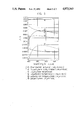
- FIG. 5 is a graph showing exemplary results of measurement.
- FIG. 1 shows an embodiment of the invention which comprises a light source 1 and a filter plate 2 having changeably attached thereto two monochromatic filters 2a and 2b each for passing light of a single wavelength therethrough. These filters differ from each other in the wavelength of light passing therethrough, such that one of two kinds of light, ⁇ 1 and ⁇ 2 in wavelength, is available from the light source 1 selectively.
- a polarizer 3 and an analyzer 5 are rotatable together by a motor 7 with their directions of polarization maintained at a specified angle with each other, e.g., in parallel to each other in the present embodiment.
- Indicated at 4 is a sample interposed between the polarizer 3 and the analyzer 5, and at 6 a photodetector for receiving the light through the anaylizer 5 to produce a signal in accordance with the intensity of the light.
- a computer 10 receives through an interface 9 the output signal from the photodetector 6 and an output signal from a rotation angle sensor 8 attached to the motor shaft for data processing and controlling the motor 7. The result of data processing by the computer 10 is displayed on a CRT 11 and recorded by a printer 12.
- a keyboard 13 is used for giving the computer 10 various commands and parameters required for data processing.
- FIG. 2 is a graph obtained from an output of the device wherein the filter 2a is selected with a sample placed at the illustrated position, by expressing the output on a polar coordinate system as a function ⁇ of the angle of rotation of the polarizer 3 and the analyzer 5 rotatable together.
- the light transmitted through the sample is generally ellipically polarized light, and the ratio between the major axis and the minor axis thereof and the direction of the major axis vary with the thickness of the sample.
- FIG. 3 shows the indicatrix of the sample, in which X-axis and Y-axis are coordinate axes on a plane perpendicular to the optical Z-axis of the device.
- n1 and n2 are two main refractive indexes
- AA' and BB' are the directions of the respective main refractive indexes n1, n2,
- PP' are the direction of polarization of the polarizer and the analyzer.
- the direction of polarization PP' is a direction QQ' which is intermediate between the directions AA' and BB' and at 45° with the directions AA' and BB'
- the component in the direction AA' and the component in the direction BB' of the linearly polarized light incident on the sample are equal to each other in amplitude, and the amplitude is 1 ⁇ 2 of the amplitude of the incident light, A.
- the emergent light becomes linearly polarized light in the direction QQ' which is equal to the incident light in amplitude, and the output of the photodetector is the same as that obtained when the direction of polarization of the polarizer and the analyzer is the direction AA' or BB'.
- the phase difference between the components of the light transmitted through the sample in the two directions of main refractive indexes is 90° when the direction of polarization, PP', is the direction QQ', the transmitted light is circularly polarized light with an amplitude of A/ ⁇ 2, and the intensity of light detected is 1/2 of the maximum.
- the transmitted light is linearly polarized in a direction perpendicular to the direction of the polarized light obtained when the phase difference is 0 and is prevented by the analyzer to give a light detection signal of 0.
- the phase difference involved in the transmitted light in the two directions of the main refractive indexes can be known from the ratio of the light detection signal value in the direction at an angle of 45° with the direction in which the maximal value is obtained in FIG. 2 to the maximum value of the light detection signal.
- the two main refractive indexes n1, n2 to be determined from the phase difference involved in the transmitted light will be considered. Since there are two unknowns, the two main refractive indexes can not be determined if the data as to the phase difference is a single item. Accordingly, the second filter 2b is selected to perform the same measurement as above.
- the direction of polarization of the polarizer and the analyzer is the direction QQ', the phase difference between the components in the two directions of main refractive indexes of the sample transmitted light differs from the value obtained with the filter 2a.
- two kinds of light with wavelengths ⁇ 1, ⁇ 2 are selected which are so close to each other in wavelength that they can be regarded as substantially identical in main refractive indexes. It is then possible to determine the two main refractive indexes n1 and n2 in the following manner.
- the number of waves, N1, of light with the wavelength ⁇ 1 within the sample at the refractive index n1 is given by
- the phase difference ⁇ 1 involved in the light emanating from the sample in the two ##EQU1##
- the direction of polarization of the polarizer and the analyzer is the direction QQ' in FIG. 3
- the components of the incident light in the two directions of main refractive indexes have the same phase and the same amplitude, so that the amplitude of the emanating light with the phase difference of ⁇ 1 can be determined by the following method.
- the absorption coefficient of the sample is not different with the direction of polarization.
- the amplitude of the component in the direction of main refractive index n1 is A/ ⁇ 2
- the amplitude of the component thereof in the direction QQ' is A/2.
- the amplitude of this component is expressed as (A/2)cos ⁇ t
- the component in the direction QQ' of the component in the direction of main refractive index n2 is expressed by
- the absorption coefficient of the sample does not vary with the direction of polarization.
- the ratio of the absorption coefficient a1 to the absorption coefficient a2, i.e., a1/a2 is assumed to be ⁇ .
- the absorption coefficient ratio is dependent on the photodetector output ratio when the direction of polarization of the polarizer and the analyzer is the directions AA' and BB' and the square root thereof is assumed to be ⁇ .
- R1, R2, ⁇ 1 and ⁇ 2 in the equations (5) and (6) are actual measurements, so that T(n1-n2) can be determined in the same manner as above.
- Each of R1 and R2 used is the ratio of the photodetector output in the direction of the main refractive index n1, i.e., the direction AA' in FIG. 3, to the photodetector output in the direction QQ', because the above calculations are based on these directions.
- the six samples used were PET (polyethylene terephthalate; 58/ ⁇ m), FEP (fluorinated polymer; 148/ ⁇ m), PS (polystyrene; 48/ ⁇ m), PP (polypropylene; 28/ ⁇ m), PS (polystyrene; 111/ ⁇ m) and PP (polypropylene; 28/ ⁇ m).
- PET polyethylene terephthalate
- FEP fluorinated polymer
- PS polystyrene
- PP polypropylene
- PS polystyrene; 111/ ⁇ m
- PP polypropylene; 28/ ⁇ m
- the use of the Berek compensator has the drawback that the error increases as Rt increases because of the characteristics thereof and that different measurers produce different values.
- the standard deviation of Rt was up to 0.1 nm, hence high accuracy.
- FIG. 4 shows another embodiment of the invention wherein a filter plate 2 has replaceably attached thereto three monochromatic filters 2a, 2b and 2c which are different in the wavelength of light to be passed therethrough, and the light of one of three wavelengths ⁇ 1, ⁇ 2 and ⁇ 3 form a light source 1 is made available selectively.
- the device is the same as the one shown in FIG. 1.
- Like parts are designated by like reference numerals. This device is used in the same manner as the device of FIG. 1.
- the two main refractive indexes of the sample are n11 and n12 for the light of wavelength ⁇ 1, n21 and n22 for the light of wavelength ⁇ 2, and n31 and n32 for the light of wavelength ⁇ 3, and the thickness of the sample is T.
- the light absorption coefficient of the sample does not differ with the direction of polarization. It is assumed that the light incident on the sample is linealy polarized light in the direction QQ' with an amplitude of A and that the component of light emanating from the sample in the direction QQ' has an amplitude of Aq.
- the ratio between the maximum and the minimum of the photodetector output Aq 2 /A 2 i.e., R1
- R1 the ratio between the maximum and the minimum of the photodetector output Aq 2 /A 2
- R2 and R3 for the measurement with wavelengths ⁇ 2 and ⁇ 3 are expressed by ##EQU16## which are obtained by changing the adscript in the equation (11) to 2 and 3, respectively.
- R1, R2 and R3 in the equations (11), (12) and (13) are measured values, and ⁇ 1, ⁇ 2 and ⁇ 3 and the thickness of the sample, T, are known, so that n11, n12, etc. can be calculated from the equations (11) to (13).
- ⁇ 2 and ⁇ 3 are obtained on the basis of a21, a22 and a31, a32.
- the ratio of absorption coefficients is dependent on the ratio between the photodectector outputs when the direction of polarization of the polarizer and the analyzer is AA' and BB'.
- Rl, R2, R3, ⁇ 1, ⁇ 2, and ⁇ 3 in the equations (17), (18) and (19) are actual measurements, so that T(n11-n12), etc. can be determined in the same manner as above.
- Each of Rl, R2 and R3 used is the ratio of the photodetector output in the direction of the main refractive index n11 or the like, i.e., the direction AA' in FIG. 3, to the photodetector output in the direction QQ', because the above calculations are based on these directions.
- the retardation values T(n11-n12), etc. of the sample are determined for the respective kinds of light with the wavelengths ⁇ 1, ⁇ 2 and ⁇ 3.
- the relation between the wavelength and the difference between the two main refractive indexes, i.e. birefringence n1-n2 is then determined in the following manner.
- the relation between the refractive index n and the wavelength ⁇ of visible light can be expressed approximately by Cauchy's formula, i.e., by ##EQU24## where a, b and c are constants dependent on the substance concerned. Considering that these values differ in the respective directions of major axis and minor axis of the indicatrix as a1, a2; b1, b2; and c1, c2, we obtain ##EQU25## Assuming that the birefringence is ⁇ n( ⁇ ), this value can be expressed as ##EQU26## where p, q and Y are coefficients relating to the wavelength dependence of the birefringence.
- FIG. 5 shows the wavelength dependence of birefringence of the samples as determined with use of the values p, q and ⁇ over the wavelength range of 400 nm to 750 nm.
- the six samples used were films of FEP (fluorinated polymer), PS (polystyrene), PET (polyethylene terephthalate) or PP (polypropylene).
- FIG. 5 reveals that the wavelength dependence of double refraction differs with different samples. In this way, it is possible according to the present invention to determine the dispersion of birefringence and the value of birefringence at an optional wavelength in the visible region.
Landscapes
- Physics & Mathematics (AREA)
- Health & Medical Sciences (AREA)
- Life Sciences & Earth Sciences (AREA)
- Chemical & Material Sciences (AREA)
- Analytical Chemistry (AREA)
- Biochemistry (AREA)
- General Health & Medical Sciences (AREA)
- General Physics & Mathematics (AREA)
- Immunology (AREA)
- Pathology (AREA)
- Investigating Or Analysing Materials By Optical Means (AREA)
Abstract
Description
N1=n1×T/λ1
N2=n2×T/λ1
(A/2)cos (ωt-Δ1)
              TABLE 1
______________________________________
             Retardation value measured (nm)
       Thickness
               With
       of      Berek
       sample  comp-   Method of invention
No.  Sample  (μm)   ensator
                             λ = 590.0 nm
                                      λ = 657.3 nm
______________________________________
1    PET     58         51    50.8     48.4
2    FEP     148       102   102.4    101.2
3    PS      48        221   219.0    215.4
4    PP      28        431   417.6    417.7
5    PS      111       637   623.7    608.2
6    PP      28        804   791.7    790.4
______________________________________
                                  TABLE 2
__________________________________________________________________________
Sample      Birefringence
Thickness   Δn measured (nm)
                                 Coefficient of Eq. (22)
No.
   Kind
      (μm)
            λ = 487.5 nm
                   λ = 590.0 nm
                          λ = 657.3 nm
                                 P   q (m.sup.2)
                                               r (m.sup.4)
__________________________________________________________________________
1  FEP
      148   0.00072
                   0.00069
                          0.00068
                                 0.00066
                                     3.0195 × 10.sup.-18
                                                2.2183 × 10.sup.-30
                                               8
2  PET
      58    0.00086
                   0.00088
                          0.00083
                                 0.00036
                                     3.1266 × 10.sup.-16
                                               -4.5981 × 10.sup.-29
                                               1
3  PS 60    0.00566
                   0.00541
                          0.00518
                                 0.00351
                                     9.7996 × 10.sup.-16
                                               1.1178 × 10.sup.-28
4  PET
      15    0.00733
                   0.00690
                          0.00680
                                 0.00688
                                     -2.0563 × 10.sup.-16
                                                7.4179 × 10.sup.-29
                                               2
5  PET
      44    0.00703
                   0.00712
                          0.00680
                                 0.00328
                                     2.2894 × 10.sup.-15
                                               -3.3223 × 10.sup.-28
                                               .
6  PP 59    0.01221
                   0.01235
                          0.01238
                                 0.01237
                                     5.4630 × 10.sup.-17
                                               -2.2239 × 10.sup.-29
__________________________________________________________________________
Claims (4)
Applications Claiming Priority (4)
| Application Number | Priority Date | Filing Date | Title |
|---|---|---|---|
| JP63-254484 | 1988-10-08 | ||
| JP63254484A JP2791480B2 (en) | 1988-10-08 | 1988-10-08 | How to measure retardation, etc. |
| JP63-254483 | 1988-10-08 | ||
| JP63254483A JP2791479B2 (en) | 1988-10-08 | 1988-10-08 | Retardation measurement method |
Publications (1)
| Publication Number | Publication Date |
|---|---|
| US4973163A true US4973163A (en) | 1990-11-27 |
Family
ID=26541701
Family Applications (1)
| Application Number | Title | Priority Date | Filing Date |
|---|---|---|---|
| US07/417,177 Expired - Lifetime US4973163A (en) | 1988-10-08 | 1989-10-04 | Method for measuring birefringence |
Country Status (1)
| Country | Link |
|---|---|
| US (1) | US4973163A (en) |
Cited By (33)
| Publication number | Priority date | Publication date | Assignee | Title |
|---|---|---|---|---|
| US5141110A (en) * | 1990-02-09 | 1992-08-25 | Hoover Universal, Inc. | Method for sorting plastic articles |
| GB2265458A (en) * | 1992-03-28 | 1993-09-29 | Rover Group | Multi-wavelength photoelastic stress analysis |
| US5311284A (en) * | 1991-07-12 | 1994-05-10 | Casio Computer Co., Ltd. | Method of measuring optical characteristics of thin film and apparatus therefor |
| US5406371A (en) * | 1991-07-29 | 1995-04-11 | New Oji Paper Co., Ltd. | Apparatus for measuring birefringence and retardation |
| US5434671A (en) * | 1992-12-25 | 1995-07-18 | Nec Corporation | Birefringent member cell gap measurement method and instrument |
| US5450200A (en) * | 1993-03-31 | 1995-09-12 | New Oji Paper Co., Ltd. | Method of and apparatus for measuring birefringence |
| WO1996010168A1 (en) * | 1994-09-27 | 1996-04-04 | Bestsénse Oy | Method and device for determining the orientation angle of the optical axis and the relative phase retardation of a birefringent specimen |
| US5532823A (en) * | 1993-03-08 | 1996-07-02 | Matsushita Electric Industrial Co., Ltd. | Method of measuring optical characteristics of liquid crystal cells, measurement equipment therefor and method for manufacturing liquid crystal devices |
| US5627645A (en) * | 1994-09-30 | 1997-05-06 | New Oji Paper Co., Ltd. | Method of and apparatus for measuring retardation of composite layer |
| US5661560A (en) * | 1993-08-23 | 1997-08-26 | Nippon Telegraph And Telephone Public Corporation | Elliptical light measuring method |
| WO1998006059A1 (en) * | 1996-07-18 | 1998-02-12 | Medar, Inc. | Method and system for detecting localized birefringence defects in a dynamic global birefringence field |
| US5825492A (en) * | 1996-04-26 | 1998-10-20 | Jaton Systems Incorporated | Method and apparatus for measuring retardation and birefringence |
| US5864403A (en) * | 1998-02-23 | 1999-01-26 | National Research Council Of Canada | Method and apparatus for measurement of absolute biaxial birefringence in monolayer and multilayer films, sheets and shapes |
| US5917598A (en) * | 1995-12-05 | 1999-06-29 | Jatom Systems Incorporated | Method and apparatus for measuring the orientation of optical axes |
| US6014197A (en) * | 1995-02-28 | 2000-01-11 | U.S. Philips Corporation | Electro-optical device wherein orientation layers have grating structure and comprises birefringent material with refractive indices equal to electro-optic medium |
| US6268914B1 (en) | 2000-01-14 | 2001-07-31 | Hinds Instruments, Inc. | Calibration Process For Birefringence Measurement System |
| US6473179B1 (en) | 1998-02-20 | 2002-10-29 | Hinds Instruments, Inc. | Birefringence measurement system |
| US6473181B1 (en) | 1997-07-28 | 2002-10-29 | Hinds Instruments, Inc. | Measurement of waveplate retardation using a photoelastic modulator |
| US20030076487A1 (en) * | 2001-08-03 | 2003-04-24 | Cannon Bret D. | System and method for glass processing and stress measurement |
| US6693710B1 (en) | 2000-06-16 | 2004-02-17 | Cambridge Research & Instrumentation Inc. | Polarization imaging system |
| US6697157B2 (en) * | 1999-05-24 | 2004-02-24 | Hinds Instruments | Birefringence measurement |
| US20040114142A1 (en) * | 2001-06-18 | 2004-06-17 | Hinds Instruments, Inc. | Birefringence measurement at deep-ultraviolet wavelengths |
| US20050068530A1 (en) * | 2003-09-25 | 2005-03-31 | Montarou Carole C. | Performing retardation measurements |
| US20050068529A1 (en) * | 2003-09-25 | 2005-03-31 | Montarou Carole C. | Performing retardation measurements |
| US20050068531A1 (en) * | 2003-09-25 | 2005-03-31 | Montarou Carole C. | Performing retardation measurements |
| DE102004051247B3 (en) * | 2004-10-20 | 2006-04-06 | Thüringisches Institut für Textil- und Kunststoff-Forschung e.V. | Fast measurement of high path differences of birefringent media with and without false colors by simultaneous combination of the multicolor Senarmont method with discrete Fourier analysis |
| US20070146723A1 (en) * | 2005-06-20 | 2007-06-28 | Chuss David T | Interferometric polarization control |
| US20080001055A1 (en) * | 2006-05-26 | 2008-01-03 | Hinds Instruments, Inc | Support for vibrating optical assembly |
| DE102006062157A1 (en) * | 2006-12-22 | 2008-06-26 | Thüringisches Institut für Textil- und Kunststoff-Forschung e.V. | Birefringent and transparent optical media/probe retardation measuring and optical axis orientation position detecting method, involves aborting rotation of measuring system after reaching light intensity minimum, where system is measurable |
| US11643355B2 (en) | 2016-01-12 | 2023-05-09 | Corning Incorporated | Thin thermally and chemically strengthened glass-based articles |
| US11697617B2 (en) | 2019-08-06 | 2023-07-11 | Corning Incorporated | Glass laminate with buried stress spikes to arrest cracks and methods of making the same |
| US11891324B2 (en) | 2014-07-31 | 2024-02-06 | Corning Incorporated | Thermally strengthened consumer electronic glass and related systems and methods |
| US12064938B2 (en) | 2019-04-23 | 2024-08-20 | Corning Incorporated | Glass laminates having determined stress profiles and methods of making the same |
Citations (5)
| Publication number | Priority date | Publication date | Assignee | Title |
|---|---|---|---|---|
| US3177761A (en) * | 1963-09-09 | 1965-04-13 | Photolastic Inc | Polariscope having simultaneously rotatable waveplates |
| US3376652A (en) * | 1966-06-17 | 1968-04-09 | Luis A. Hernandez Jr. | Low temperature freeze drying process and apparatus therefor |
| US4554449A (en) * | 1982-04-30 | 1985-11-19 | Matsushita Electric Industrial Co., Ltd. | Fiber optic magnetic field sensor |
| SU1402857A1 (en) * | 1986-07-07 | 1988-06-15 | Львовский Государственный Университет | Method of orienting gyrotropic crystals in polarization-optical system |
| US4849623A (en) * | 1985-12-30 | 1989-07-18 | Kanzaki Paper Manufacturing Co., Ltd. | System and method for determining anisotropy of light-transmitting sheet specimen |
-
1989
- 1989-10-04 US US07/417,177 patent/US4973163A/en not_active Expired - Lifetime
Patent Citations (5)
| Publication number | Priority date | Publication date | Assignee | Title |
|---|---|---|---|---|
| US3177761A (en) * | 1963-09-09 | 1965-04-13 | Photolastic Inc | Polariscope having simultaneously rotatable waveplates |
| US3376652A (en) * | 1966-06-17 | 1968-04-09 | Luis A. Hernandez Jr. | Low temperature freeze drying process and apparatus therefor |
| US4554449A (en) * | 1982-04-30 | 1985-11-19 | Matsushita Electric Industrial Co., Ltd. | Fiber optic magnetic field sensor |
| US4849623A (en) * | 1985-12-30 | 1989-07-18 | Kanzaki Paper Manufacturing Co., Ltd. | System and method for determining anisotropy of light-transmitting sheet specimen |
| SU1402857A1 (en) * | 1986-07-07 | 1988-06-15 | Львовский Государственный Университет | Method of orienting gyrotropic crystals in polarization-optical system |
Cited By (47)
| Publication number | Priority date | Publication date | Assignee | Title |
|---|---|---|---|---|
| US5141110A (en) * | 1990-02-09 | 1992-08-25 | Hoover Universal, Inc. | Method for sorting plastic articles |
| US5311284A (en) * | 1991-07-12 | 1994-05-10 | Casio Computer Co., Ltd. | Method of measuring optical characteristics of thin film and apparatus therefor |
| US5406371A (en) * | 1991-07-29 | 1995-04-11 | New Oji Paper Co., Ltd. | Apparatus for measuring birefringence and retardation |
| GB2265458A (en) * | 1992-03-28 | 1993-09-29 | Rover Group | Multi-wavelength photoelastic stress analysis |
| US5400131A (en) * | 1992-03-28 | 1995-03-21 | Rover Group Limited | Photoelastic stress analysis |
| US5434671A (en) * | 1992-12-25 | 1995-07-18 | Nec Corporation | Birefringent member cell gap measurement method and instrument |
| US5532823A (en) * | 1993-03-08 | 1996-07-02 | Matsushita Electric Industrial Co., Ltd. | Method of measuring optical characteristics of liquid crystal cells, measurement equipment therefor and method for manufacturing liquid crystal devices |
| US5450200A (en) * | 1993-03-31 | 1995-09-12 | New Oji Paper Co., Ltd. | Method of and apparatus for measuring birefringence |
| US5661560A (en) * | 1993-08-23 | 1997-08-26 | Nippon Telegraph And Telephone Public Corporation | Elliptical light measuring method |
| WO1996010168A1 (en) * | 1994-09-27 | 1996-04-04 | Bestsénse Oy | Method and device for determining the orientation angle of the optical axis and the relative phase retardation of a birefringent specimen |
| US5627645A (en) * | 1994-09-30 | 1997-05-06 | New Oji Paper Co., Ltd. | Method of and apparatus for measuring retardation of composite layer |
| US6014197A (en) * | 1995-02-28 | 2000-01-11 | U.S. Philips Corporation | Electro-optical device wherein orientation layers have grating structure and comprises birefringent material with refractive indices equal to electro-optic medium |
| US5917598A (en) * | 1995-12-05 | 1999-06-29 | Jatom Systems Incorporated | Method and apparatus for measuring the orientation of optical axes |
| US5825492A (en) * | 1996-04-26 | 1998-10-20 | Jaton Systems Incorporated | Method and apparatus for measuring retardation and birefringence |
| WO1998006059A1 (en) * | 1996-07-18 | 1998-02-12 | Medar, Inc. | Method and system for detecting localized birefringence defects in a dynamic global birefringence field |
| US5757978A (en) * | 1996-07-18 | 1998-05-26 | Medar, Inc. | Method and system for detecting localized birefringence defects in a dynamic global birefringence field |
| US6473181B1 (en) | 1997-07-28 | 2002-10-29 | Hinds Instruments, Inc. | Measurement of waveplate retardation using a photoelastic modulator |
| US6473179B1 (en) | 1998-02-20 | 2002-10-29 | Hinds Instruments, Inc. | Birefringence measurement system |
| US5864403A (en) * | 1998-02-23 | 1999-01-26 | National Research Council Of Canada | Method and apparatus for measurement of absolute biaxial birefringence in monolayer and multilayer films, sheets and shapes |
| US6697157B2 (en) * | 1999-05-24 | 2004-02-24 | Hinds Instruments | Birefringence measurement |
| US6268914B1 (en) | 2000-01-14 | 2001-07-31 | Hinds Instruments, Inc. | Calibration Process For Birefringence Measurement System |
| US6693710B1 (en) | 2000-06-16 | 2004-02-17 | Cambridge Research & Instrumentation Inc. | Polarization imaging system |
| US20040114142A1 (en) * | 2001-06-18 | 2004-06-17 | Hinds Instruments, Inc. | Birefringence measurement at deep-ultraviolet wavelengths |
| US6985227B2 (en) | 2001-06-18 | 2006-01-10 | Hinds Instruments, Inc. | Birefringence measurement at deep-ultraviolet wavelengths |
| US20030076487A1 (en) * | 2001-08-03 | 2003-04-24 | Cannon Bret D. | System and method for glass processing and stress measurement |
| US20050068530A1 (en) * | 2003-09-25 | 2005-03-31 | Montarou Carole C. | Performing retardation measurements |
| US20050068529A1 (en) * | 2003-09-25 | 2005-03-31 | Montarou Carole C. | Performing retardation measurements |
| US20050068531A1 (en) * | 2003-09-25 | 2005-03-31 | Montarou Carole C. | Performing retardation measurements |
| US7075648B2 (en) | 2003-09-25 | 2006-07-11 | Georgia Tech Research Corporation | Performing retardation measurements |
| US7224457B2 (en) | 2003-09-25 | 2007-05-29 | Georgia Tech Research Corporation | Performing retardation measurements |
| US7233395B2 (en) | 2003-09-25 | 2007-06-19 | Georgia Tech Research Corporation | Performing retardation measurements |
| DE102004051247B3 (en) * | 2004-10-20 | 2006-04-06 | Thüringisches Institut für Textil- und Kunststoff-Forschung e.V. | Fast measurement of high path differences of birefringent media with and without false colors by simultaneous combination of the multicolor Senarmont method with discrete Fourier analysis |
| US20070146723A1 (en) * | 2005-06-20 | 2007-06-28 | Chuss David T | Interferometric polarization control |
| US7616903B2 (en) | 2005-06-20 | 2009-11-10 | The United States Of America As Represented By The Administrator Of The National Aeronautics And Space Administration | Interferometric polarization control |
| US7412175B2 (en) | 2005-06-20 | 2008-08-12 | The United States Of America As Represented By The Administrator Of The National Aeronautics And Space Administration | Interferometric polarization control |
| US20080231529A1 (en) * | 2005-06-20 | 2008-09-25 | U.S.A. as represented by the Administrator of the National Aeronautics and Space Admi | Interferometric polarization control |
| US20080238791A1 (en) * | 2005-06-20 | 2008-10-02 | United States Of America As Represented By The Administrator Of The National Aeronautics And Spac | Interferometric polarization control |
| US7609978B2 (en) | 2005-06-20 | 2009-10-27 | The United States Of America As Represented By The National Aeronautics And Space Administration | Interferometric polarization control |
| US7800845B2 (en) | 2006-05-26 | 2010-09-21 | Hinds Instruments, Inc. | Support for vibrating optical assembly |
| US20080001055A1 (en) * | 2006-05-26 | 2008-01-03 | Hinds Instruments, Inc | Support for vibrating optical assembly |
| DE102006062157B4 (en) * | 2006-12-22 | 2008-09-04 | Thüringisches Institut für Textil- und Kunststoff-Forschung e.V. | Simultaneous measurement of high path differences and the rotation of the optical axis of birefringent media |
| DE102006062157A1 (en) * | 2006-12-22 | 2008-06-26 | Thüringisches Institut für Textil- und Kunststoff-Forschung e.V. | Birefringent and transparent optical media/probe retardation measuring and optical axis orientation position detecting method, involves aborting rotation of measuring system after reaching light intensity minimum, where system is measurable |
| US11891324B2 (en) | 2014-07-31 | 2024-02-06 | Corning Incorporated | Thermally strengthened consumer electronic glass and related systems and methods |
| US11643355B2 (en) | 2016-01-12 | 2023-05-09 | Corning Incorporated | Thin thermally and chemically strengthened glass-based articles |
| US12064938B2 (en) | 2019-04-23 | 2024-08-20 | Corning Incorporated | Glass laminates having determined stress profiles and methods of making the same |
| US11697617B2 (en) | 2019-08-06 | 2023-07-11 | Corning Incorporated | Glass laminate with buried stress spikes to arrest cracks and methods of making the same |
| US12043575B2 (en) | 2019-08-06 | 2024-07-23 | Corning Incorporated | Glass laminate with buried stress spikes to arrest cracks and methods of making the same |
Similar Documents
| Publication | Publication Date | Title |
|---|---|---|
| US4973163A (en) | Method for measuring birefringence | |
| US4647207A (en) | Ellipsometric method and apparatus | |
| US5864403A (en) | Method and apparatus for measurement of absolute biaxial birefringence in monolayer and multilayer films, sheets and shapes | |
| US4668086A (en) | Stress and strain measuring apparatus and method | |
| Hawranek et al. | The control of errors in ir spectrophotometry—IV. Corrections for dispersion distortion and the evaluation of both optical constants | |
| US5151752A (en) | Method of measuring refractive indices of lens and sample liquid | |
| US3902805A (en) | Automatic birefringence measuring apparatus | |
| Redner | Photoelastic measurements by means of computer-assisted spectral-contents analysis | |
| CA2293369A1 (en) | Extended range interferometric refractometer | |
| KR100195397B1 (en) | Method and apparatus for measuring thickness of birefringence layer | |
| US3797940A (en) | Refractometer with displacement measured polarimetrically | |
| US5517022A (en) | Apparatus for measuring an ambient isotropic parameter applied to a highly birefringent sensing fiber using interference pattern detection | |
| EP0737856B1 (en) | A method of investigating samples by changing polarisation | |
| JP2791479B2 (en) | Retardation measurement method | |
| Okabe et al. | Error-reduced channeled spectroscopic ellipsometer with palm-size sensing head | |
| EP0144115B1 (en) | An ellipsometer | |
| CN110631805A (en) | Device and method for measuring performance of broadband wave plate by using AOTF monochromatic light | |
| Salik | Quantitative investigation of Fresnel reflection coefficients by polarimetry | |
| Rosa | The inverse problem of ellipsometry: a bootstrap approach | |
| JPH02116732A (en) | Method and apparatus for optical measurement | |
| US5946096A (en) | Heterodyne interferometry method for measuring physical parameters of medium | |
| JP2791480B2 (en) | How to measure retardation, etc. | |
| UA77409C2 (en) | Method for measuring the parameters of a transparent liquid-crystal cell | |
| JP2927019B2 (en) | Birefringence measurement method | |
| CN210863099U (en) | Device for measuring performance of broadband wave plate by using AOTF monochromatic light |
Legal Events
| Date | Code | Title | Description |
|---|---|---|---|
| AS | Assignment |
Owner name: KANZAKI PAPER MANUFACTURING CO., LTD., JAPAN Free format text: ASSIGNMENT OF ASSIGNORS INTEREST.;ASSIGNORS:SAKAI, KIYOKAZU;OSAKI, SHIGEYOSHI;REEL/FRAME:005243/0881 Effective date: 19890925 |
|
| STCF | Information on status: patent grant |
Free format text: PATENTED CASE |
|
| FEPP | Fee payment procedure |
Free format text: PAYER NUMBER DE-ASSIGNED (ORIGINAL EVENT CODE: RMPN); ENTITY STATUS OF PATENT OWNER: LARGE ENTITY Free format text: PAYOR NUMBER ASSIGNED (ORIGINAL EVENT CODE: ASPN); ENTITY STATUS OF PATENT OWNER: LARGE ENTITY |
|
| FPAY | Fee payment |
Year of fee payment: 4 |
|
| AS | Assignment |
Owner name: NEW OJI PAPER CO., LTD., JAPAN Free format text: CHANGE OF NAME;ASSIGNOR:KANZAKI PAPER MANUFACTURING CO., LTD.;REEL/FRAME:007007/0605 Effective date: 19940308 |
|
| FPAY | Fee payment |
Year of fee payment: 8 |
|
| FPAY | Fee payment |
Year of fee payment: 12 |