US4949620A - Edge-reinforced packing for use in steam service - Google Patents
Edge-reinforced packing for use in steam service Download PDFInfo
- Publication number
- US4949620A US4949620A US07/287,916 US28791688A US4949620A US 4949620 A US4949620 A US 4949620A US 28791688 A US28791688 A US 28791688A US 4949620 A US4949620 A US 4949620A
- Authority
- US
- United States
- Prior art keywords
- packing
- wire
- reinforced
- yarns
- valve stem
- Prior art date
- Legal status (The legal status is an assumption and is not a legal conclusion. Google has not performed a legal analysis and makes no representation as to the accuracy of the status listed.)
- Expired - Lifetime
Links
Images


Classifications
-
- F—MECHANICAL ENGINEERING; LIGHTING; HEATING; WEAPONS; BLASTING
- F16—ENGINEERING ELEMENTS AND UNITS; GENERAL MEASURES FOR PRODUCING AND MAINTAINING EFFECTIVE FUNCTIONING OF MACHINES OR INSTALLATIONS; THERMAL INSULATION IN GENERAL
- F16J—PISTONS; CYLINDERS; SEALINGS
- F16J15/00—Sealings
- F16J15/16—Sealings between relatively-moving surfaces
- F16J15/18—Sealings between relatively-moving surfaces with stuffing-boxes for elastic or plastic packings
- F16J15/20—Packing materials therefor
- F16J15/22—Packing materials therefor shaped as strands, ropes, threads, ribbons, or the like
-
- D—TEXTILES; PAPER
- D04—BRAIDING; LACE-MAKING; KNITTING; TRIMMINGS; NON-WOVEN FABRICS
- D04C—BRAIDING OR MANUFACTURE OF LACE, INCLUDING BOBBIN-NET OR CARBONISED LACE; BRAIDING MACHINES; BRAID; LACE
- D04C1/00—Braid or lace, e.g. pillow-lace; Processes for the manufacture thereof
- D04C1/06—Braid or lace serving particular purposes
- D04C1/12—Cords, lines, or tows
-
- D—TEXTILES; PAPER
- D10—INDEXING SCHEME ASSOCIATED WITH SUBLASSES OF SECTION D, RELATING TO TEXTILES
- D10B—INDEXING SCHEME ASSOCIATED WITH SUBLASSES OF SECTION D, RELATING TO TEXTILES
- D10B2505/00—Industrial
- D10B2505/06—Packings, gaskets, seals
Definitions
- This invention relates to packing material for steam service and more particularly to a method and apparatus for minimizing steam leakage and extending packing life by providing a wire-reinforced packing material which results in minimum valve-stem wear, and a convenient orientation-independent installation.
- prior steam service packings have been made on round braiders. Typically they use a resilient or pliable core material completely surrounded by a braided material in which the braid contains wire, usually Inconnel.
- the packing is surrounded with reinforcing wire, which under pressure slices through the braid, contacts the valve stem and scores it because the Inconnel wire is harder than the commonly used steel or stainless steel valve stems. This causes leakage and subsequent catastrophic failure if the packing is not replaced frequently.
- the abraided particles from the valve stem also can cause packing failure, which with high pressure steam presents a very serious hazard, especially to those employed to repair a leak.
- Prior steam service packings include Crane style 187-I or Chesterton style 1500 which utilize a so-called "plastic" or flexible core of high purity asbestos, graphite flake, rubber, zinc and oil surrounded by wire-reinforced asbestos which is braided around the plastic core.
- the circumferential wire reinforcement of these packings and packing of similar construction present an overly abundant amount of wire to the valve stem, and with constant cycling of the valve stem requires repacking and valve reconstruction as early as three months due to valve stem wear.
- non-wire reinforced packings are used for low pressure applications in which a sturdier secondary yarn is braided on diagonal tracks to give packings strength, especially at their edges.
- Such diagonally-reinforced packings are described in U.S. Pat. Application Ser. No. 943,950, filed Dec. 18, 1986 and now U.S. Pat. No. 4,802,398 assigned to the assignee hereof. Whether single or double diagonals are reinforced, none of the packings described in this Patent Application are used for steam service. Nor are they wire-reinforced.
- the Subject System involves a reinforced non-asbestos packing in which the wire utilized is provided only on packing edges. This eliminates the use of wire between the inner edges, which reduces the amount of wire contacting the valve stem by as much as 80%. It has been found that edge reinforcing is all that is necessary for preventing steam leakage. By using a interlocking braider and a double diagonal wire-reinforced braid all edges are reinforced so that there can be no problem with backward or upside down installation of the packing. A single diagonal can be reinforced with wire, as long as there are markings on the packing so that it can be installed with the reinforced edge properly presented to the steam at the stem surface.
- an alternating double diagonal braid is used to reduce the amount of wire which contacts the valve stem to only 18% of the braid touching the valve stem, thus minimizing abrasion.
- alternating carriers on both diagonal tracks carry the wire-reinforced secondary yarn.
- the wire-reinforced braid As opposed to the Parker braid, here there is an offset in the wire-reinforced braid which results in complete circumferential sealing. This is produced by selecting which of the alternating carriers on each diagonal track carry the wire-reinforced yarn, such that the offset occurs. Should there be insufficient offset to provide a completely circumferential reinforced barrier to the steam due to an incomplete overlap of offset wire-reinforced yarns, this deficiency can be overcome using the keystone-resisting techniques of U.S. Pat.
- all core and braid yarns are made of graphite or carbon. This eliminates, shrinkage, hardening or disintegration associated with asbestos packing previously used.
- the use of carbon or graphite also eliminates the problems of using fiberglass in high temperature, high pressure service.
- a double diagonally-reinforced packing does eliminate the problem of backwards mounting of packing in a stuffing box adjacent a valve stem because there is no preferential direction. It will of course be appreciated that since the aforementioned prior double diagonal braid contained no metal reinforcement and has been made from materials which have thermal limitations of 600° F., such braid was not heretofore considered for utilization in high temperature steam applications.
- edge-reinforced packing for steam service, with wire-reinforced secondary yarns at one or more pairs of diagonally opposed corners of the packing to provide the edge-reinforcing which reduces valve stem abrasion while providing sufficient resistance to high pressure, high temperature steam leakage.
- Wire-reinforcing only the edges of the packing minimizes the amount of reinforcing wire necessary to counteract high pressure steam and thus minimizes valve stem wear.
- An offset, alternating braid embodiment further reduces wire usage at the packing edges, while at the same time providing complete circumferential reinforced sealing around the valve stem.
- selected alternating yarn carriers along a diagonal track are provided with secondary yarn reinforced with wire.
- the relationship of the carriers provided with reinforcing wire is such as to provide an offset, alternating braid in which the foot print along the surface of a valve stem is such as to provide a continuous reinforced barrier to steam pressure.
- the packing is a non-asbestos packing which eliminates both hardening and packing disintegration.
- the diagonal symmetry alleviates problems associated with installing the packing backwards.
- FIG. 1A is a sectional and diagrammatic illustration of an automatic control valve for use in steam service, illustrating the utilization of the subject packing to prevent steam leakage around the valve stem;
- FIG. 1B is a diagrammatic and sectional illustration of a manual steam valve utilizing the Subject packing
- FIG. 2A is a diagrammatic illustration of a number of rings of packing having a plastic core made on a typical round braider, in which the inside surfaces of the rings are illustrated as carrying an overage of wire which contacts the surface of a valve stem shown here in dotted outline;
- FIG. 2B is a diagrammatic illustration of edge reinforcement for a packing made in accordance with the Subject Invention on a four track braider, illustrating the inside surfaces of a pair of rings and a reduction of exposed wire;
- FIG. 2C is a diagrammatic illustration of the four track braided packing of FIG. 2B in which an offset alternating braid configuration is shown in which alternating edge yarns carry reinforcing wire;
- FIG. 2D is a diagrammatic illustration of an edge-reinforced packing made in accordance with the Subject Invention on a three track braider;
- FIG. 2E is a diagrammatic illustration of an edge-reinforced packing made in accordance with the Subject Invention that can be installed with either reinforced inside edge toward the bottom of the stuffing box, in which alternating edge yarns carry reinforcing wire which presents a minimum of wire to the valve stem;
- FIG. 3 is a diagrammatic illustration of a diagonally-reinforced packing which is directionally dependent in installation in which wire is utilized along with the secondary yarn to provide diagonal edge reinforcement and which presents a minimum of wire to the valve stem;
- FIG. 4 is a diagrammatic illustration of the carriers on a single diagonal which are provided with yarn having embedded reinforcing wire for a three track interlocking braider;
- FIG. 5 is a diagrammatic illustration of a double-diagonal reinforced wire packing in which all carriers on each diagonal track are provided with yarn having embedded reinforcing wire for a three track interlocking braider;
- FIG. 6 is a diagrammatic illustration of the alternating braid embodiment in which alternating carriers are provided with yarn having embedded reinforcing wire for a three track interlocking braider;
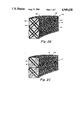
- FIG. 7A is a diagrammatic illustration of the inside surface of a prior art packing illustrating the utilization of reinforcing wires embedded in all exterior braided yarn;
- FIG. 7B is a diagrammatic illustration of the Subject Invention in which only corner yarns are provided with wire reinforcement;
- FIG. 7C is a diagrammatic illustration of an offset braid on a three track machine, illustrating the overlapping of the bottom wire-reinforced yarn with respect to the opposed top wire-reinforced yarns;
- FIG. 7D is a diagrammatic illustration of the packing of FIG. 7C illustrating longitudinal gaps which can be caused by keystoning when the braid of FIG. 7C is wrapped around a valve stem or shaft;
- FIG. 8A is a diagrammatic illustration of the effect of keystoning on the footprint of the wire-reinforced yarns on the surface of the valve stem, illustrating longitudinally running channels down the valve stem;
- FIG. 8B is an end view of the footprint pattern associated with the keystoned packing, illustrating the void channels in cross-section;
- FIG. 8C is a diagrammatic illustration of the packing of FIG. 8A in which keystoning is eliminated by a keystone-resisting original configuration, illustrating the overlapping of the alternating braids, thereby to provide a complete barrier to steam pressure;
- FIG. 8D is a diagrammatic illustration of complete circumferential protection provided by an alternating braid in which overlapping is achieved
- FIG. 8E is a diagrammatic illustration of a keystone-resisting packing for use in steam service such as illustrated in FIG. 8C;
- FIG. 9A is a diagrammatic illustration of edge reinforced packing produced on four track machine
- FIG. 9B is diagrammatic illustration of edge reinforced packing utilizing an alternating offset braid in which the bottom wire-reinforced yarn overlaps the adjacent top reinforced yarns.
- the Subject packing 10 may be utilized with a poppet control valve generally indicated by reference character 12 which includes a valve body 14 having a valve seat 16.
- a conical seal 20 is located at one end of a valve stem 22 which at its opposite end has a control rack 24 associated with a pinion 26 driven by worm gear 28.
- the worm gear is powered by motor 30 under control of a control unit 32 having as an input thereto the output of sensor 34 which, inter alia, senses either steam pressure or temperature.
- Poppet valve 12 is controlled on a continuous basis which causes the valve stem and control rack to move up and down as indicated by double ended arrow 36 in response to the rotation of pinion 26 as illustrated by double ended arrow 38.
- Valve stem 22 projects through a yoke nut 40 threaded into a yoke 42 and through a two part gland 44 and 46 in which the gland is tightened down over packing 10 via gland nuts 48 on studs 50, with the gland being secured to the stuffing box 52 that includes a flanged portion 54 through which studs 50 project.
- the packing is placed between the bottom surface 56 of gland 46 and a guide bushing 58 through which the valve stem projects and which is held in place by a set screw 60.
- valve stem 22 is threaded as can be seen at 62, with the threaded portion extending up through a yoke nut 40 to a conventional wheel 64.
- stuffing box is integrally formed in a valve bonnet 68.
- the packing typically a prior art packing ring, here illustrated at 70, is produced on a two track braider.
- the packing includes a central core 72 of resilient or plastic material completely surrounded by wire-reinforced braid consisting of yarns 72, each of which have reinforcing wire 74 embedded therein.
- the resulting braided structure is as illustrated, in which the inside surface of the packing ring is a braided structure in which wires are exposed across the entire inside surface of the packing.
- the exposed wire is illustrated by reference character 76 to present itself to the surface of a valve stem here diagrammatically illustrated at 82, in which the entire inner surface 80 of packing has wire protruding therefrom.
- What is pictured in FIG. 2A is the situation in which the packing material is placed under compression by the gland of the valve such that the Inconnel wire slices through the yarn in which it is embedded and is therefore in contact with the surface of the valve stem.
- a packing 90 made on a four track interlocking braider shows reinforcing wire 92 embedded only in yarns at the corners 94 and 96 of the packing. This is accomplished as diagrammatically illustrated by providing the bobbins on carriers running along the diagonal tracks 98 and 100 with yarns with embedded Inconnel wire. The resulting pattern illustrates that there is a central region 102 on the inside surface 104 of packing 90 which is completely devoid of wire. Because the reinforcing wire exists only at the edges of the packing, close to 80% of the wire previously thought necessary is removed. It has been demonstrated that adequate resistance to high temperature, high pressure steam is afforded by this reinforcing method.
- the packing is made of non-asbestos materials such as pure graphite filament and wire reinforced carbon fiber, with the primary yarns on a double diamond track being of pure graphite filament and with the secondary yarns used on the diagonal tracks being of carbon fiber, which yarn is available with embedded Inconnel wire. It will be noted that in FIGS. 2B and 2C the double diamond primary braid tracks are not shown for convenience.
- the amount of wire that is used can be reduced in half over that of FIG. 2B packing through an offset alternating braid so as to produce the packing illustrated at 110.
- sets of offset wires 112 and 114 create an effective reinforced barrier completely around the valve stem while at the same time using only half the wire.
- the wire content can be cut by as much as 80% over that associated with prior steam service packings. The method of producing such a braid will be discussed hereinafter.
- open track 116 and closed track 118 assuming that every other bobbin on each track is provided with reinforced yarn, the resulting pattern will be the offset overlapping structure pictured.
- the braid shown in FIG. 2C is that produced by a four track interlocking braider, whereas the corresponding three track interlocking braid is shown by packing 120 in FIG. 2D and packing 130 in FIG. 2E.
- each bobbin on each carrier running on each diagonal track 124 and 126 is provided with a secondary yarn having embedded reinforcing wire.
- the single diamond track is illustrated at 128.
- the amount of wire utilized can be reduced if the exposed wire at the edges is in an offset overlapping configuration as illustrated by wires 132 and wires 134.
- the overlapping and alternation is formed in the same manner as described in connection with FIG. 2C.
- the alternating braid is produced by virtue of having alternating bobbins carrying the wire-reinforced yarn.
- the single diamond track is illustrated by track 140.
- a diagonally reinforced packing 140 provides opposed corners or edges 142 and 144 with a wire-reinforced yarn, in which the packing is made similar to that associated with the aforementioned Patent Application, with the exception that the bobbins on diagonal track 146 carry wire-reinforced yarn as a secondary yarn, as opposed to the non-wire-reinforced secondary yarn described in the Patent Application. It is important however with respect to this embodiment, especially with respect to steam service, that the orientation of the braid be clearly marked. If the packing is put in backwards there will be immediate steam leakage because the reinforced corner adjacent surface 148 of valve stem 150 will be the trailing edge and merely flip up in the presence of steam pressure impinging on the packing from the direction indicated by arrow 152. However with appropriate marking on the packing, one can ascertain that edge 142 is adjacent surface 148, i.e. that the wire-reinforced edge 142 is presented to the steam as the leading edge of the packing.
- the diagonally reinforced braid of FIG. 3 is achieved through the utilization of bobbins 152 carrying the wire reinforced secondary yarn, in one embodiment a yarn made of carbon fiber, whereas carriers 154 on an opposed diagonal track carry only non-reinforced yarn.
- the packing shown in FIGS. 2B and 2D can be achieved by providing bobbins 160 on all diagonal tracks with wire-reinforced yarn.
- the alternating braid providing the offset wire configurations of FIGS. 2C and 2E can be produced by providing alternate bobbins on a given diagonal with the wire-reinforced yarn.
- one diagonal track is illustrated by reference character 170
- the other diagonal track is indicated by reference character 172.
- the bobbins which carry the wire-reinforced yarn are represented by the blackened "A” circles on track 170, whereas those bobbins which Carry only the secondary yarn are illustrated by the open "A” circles on this track.
- bobbins "B" which carry the wire-reinforced yarn are the blackened circles, whereas those carrying no reinforcing yarn are indicated by the open circles.
- the interior face 180 of the prior art braid includes woven yarns 182, with the shading indicating that each of the yarns carries a reinforcing wire.
- This is in contradistinction to the braid shown in FIG. 7B in which the central yarns 184 are devoid of reinforcing wire.
- This at least diagrammatically illustrates a reduction of the wire which contacts the valve stem surface.
- the braid shown in FIGS. 7A, 7B, 7C and 7D are those available from a 3 track interlocking braider.
- the alternatinq braid pattern is shown in which the shaded yarns 186 are those carrying the reinforcing wire, whereas the remainder of the yarns 188 do not carry reinforcing wire.
- longitudinal channels 190' can be left in a packing which does not have the appropriate offset of reinforced yarns 186 with respect to yarns 188.
- longitudinal channels down the valve stem which would not be reinforced and therefore subject to obstruction by the oncoming high power steam.
- This lack of overlap can be due to keystoning, when a square cross-section packing is wrapped around a cylindrical shaft.
- a valve stem 200 is provided with a conventional woven packing 202 which, when wrapped around the valve stem, assumes a keystone-type trapezoidal shape illustrated by keystoning 204.
- This provides a footprint 206 of protection which leaves channels 208 devoid of the required reinforced packing material.
- This results in the formation of longitudinal channels 208 of FIG. 8B, down the length of the valve stem 200.
- the result of the introduction of such channels is that steam leakage is virtually assured as well as eventual destruction of the packing itself.
- axial warps or warp yarns 210 conventionally used in all packings have the same density or same number, such that there is no protection against a square braid keystoning when wrapped around a cylindrical valve stem.
- FIG. 8C A method of preventing keystoning is illustrated in FIG. 8C.
- This method is described in the aforementioned patent and includes providing a packing ring 220 with a greater density of warp yarns 210 at the outer corners 212 of packing 220, whereas less dense or fewer numbers of warp yarns are used at positions 214 at the inner corners 216 of the packing.
- the resultant foot print rather than being one involving no overlap, now has the required overlap as illustrated by the relative position of leading edge reinforced yarns 220 as opposed to the corresponding trailing edge yarns 222.
- the channel 224 while existing at the leading edge, is blocked by the overlapping yarn 222 at the trailing edge.
- a complete circumferential protection is provided by virtue of the projection of the positions of the reinforced yarns onto a single plane as illustrated at 230.
- FIG. 8E The keystone-resisting packing described in the aforementioned patent is illustrated in FIG. 8E, in which the original keystone-resisting shape of the packing is illustrated by the solid line 232 which provides the packing 220 with a trapezoidal cross section equal to and opposite that which would be expected when a straight walled packing is wrapped around a cylindrical surface.
- packing 138 with the subject wire-reinforced edge is shown made on a four track interlocking braider in which all edge yarns 240 are wire-reinforced, whereas all intermediate yarns 242 carry only the secondary yarns without wire reinforcement.
- a packing 139 is shown with the subject offset braid, in which yarns 244 are wire-reinforced at the leading edge 246 of the packing, whereas an overlapping yarn 248 is wire-reinforced on the trailing edge of the packing. It will be noted as indicated by dotted lines 250 that there are no longitudinal voids in the packing such as indicated in FIG. 7D by dotted lines 190'.
- offset alternating braid is applicable to two track plait braiders which can produce the alternating weave, with four, eight or twelve carriers.
Abstract
Description
Claims (5)
Priority Applications (1)
| Application Number | Priority Date | Filing Date | Title |
|---|---|---|---|
| US07/287,916 US4949620A (en) | 1988-12-21 | 1988-12-21 | Edge-reinforced packing for use in steam service |
Applications Claiming Priority (1)
| Application Number | Priority Date | Filing Date | Title |
|---|---|---|---|
| US07/287,916 US4949620A (en) | 1988-12-21 | 1988-12-21 | Edge-reinforced packing for use in steam service |
Publications (1)
| Publication Number | Publication Date |
|---|---|
| US4949620A true US4949620A (en) | 1990-08-21 |
Family
ID=23104920
Family Applications (1)
| Application Number | Title | Priority Date | Filing Date |
|---|---|---|---|
| US07/287,916 Expired - Lifetime US4949620A (en) | 1988-12-21 | 1988-12-21 | Edge-reinforced packing for use in steam service |
Country Status (1)
| Country | Link |
|---|---|
| US (1) | US4949620A (en) |
Cited By (11)
| Publication number | Priority date | Publication date | Assignee | Title |
|---|---|---|---|---|
| EP0587153A2 (en) * | 1992-09-11 | 1994-03-16 | Mtu Motoren- Und Turbinen-Union MàNchen Gmbh | Sealing device between spaces of different fluidic pressions for relatively movable housings of aircraft engines |
| US5794504A (en) * | 1995-09-20 | 1998-08-18 | Chesterton International, Inc. | Lubricated braided packing and method of making same |
| US6020276A (en) * | 1996-03-06 | 2000-02-01 | Flexitallic Investments, Inc. | Seal material |
| US6234490B1 (en) * | 1999-07-09 | 2001-05-22 | George B. Champlin | Leakfree pumpback packing |
| US20030042691A1 (en) * | 2001-08-28 | 2003-03-06 | Katsuro Tsukamoto | Packing material and gland packing used the material |
| US20100194058A1 (en) * | 2009-02-05 | 2010-08-05 | Acs Industries, Inc. | Hybrid seals |
| US20130075978A1 (en) * | 2011-09-26 | 2013-03-28 | A.W. Chesterton Company | Methods and apparatuses for producing a braided dual-sided compression packing seal and methods of using the same |
| CN104696528A (en) * | 2013-12-05 | 2015-06-10 | 日本皮拉工业株式会社 | Gland packing |
| US9388903B2 (en) | 2012-09-26 | 2016-07-12 | A.W. Chesterton Company | Methods and apparatuses for producing a compression packing seal including a dual-sided braided jacket and methods of using the same |
| US10100444B2 (en) * | 2014-11-18 | 2018-10-16 | Nippon Pillar Packing Co., Ltd. | Yarn and gland packing |
| CN112391732A (en) * | 2020-10-27 | 2021-02-23 | 南京玻璃纤维研究设计院有限公司 | Three-dimensional woven special-shaped beam and preparation method thereof |
Citations (5)
| Publication number | Priority date | Publication date | Assignee | Title |
|---|---|---|---|---|
| US239287A (en) * | 1881-03-22 | Herman w | ||
| US741056A (en) * | 1903-04-18 | 1903-10-13 | Marshall Montgomery | Piston-packing. |
| US2562262A (en) * | 1946-01-26 | 1951-07-31 | Johns Manville | Packing |
| US3403595A (en) * | 1966-02-24 | 1968-10-01 | Garlock Inc | Graphite braided packing |
| US4550639A (en) * | 1982-12-17 | 1985-11-05 | The Seal Company Of New England | Shaped mechanical compression packing |
-
1988
- 1988-12-21 US US07/287,916 patent/US4949620A/en not_active Expired - Lifetime
Patent Citations (5)
| Publication number | Priority date | Publication date | Assignee | Title |
|---|---|---|---|---|
| US239287A (en) * | 1881-03-22 | Herman w | ||
| US741056A (en) * | 1903-04-18 | 1903-10-13 | Marshall Montgomery | Piston-packing. |
| US2562262A (en) * | 1946-01-26 | 1951-07-31 | Johns Manville | Packing |
| US3403595A (en) * | 1966-02-24 | 1968-10-01 | Garlock Inc | Graphite braided packing |
| US4550639A (en) * | 1982-12-17 | 1985-11-05 | The Seal Company Of New England | Shaped mechanical compression packing |
Cited By (21)
| Publication number | Priority date | Publication date | Assignee | Title |
|---|---|---|---|---|
| EP0587153A2 (en) * | 1992-09-11 | 1994-03-16 | Mtu Motoren- Und Turbinen-Union MàNchen Gmbh | Sealing device between spaces of different fluidic pressions for relatively movable housings of aircraft engines |
| EP0587153A3 (en) * | 1992-09-11 | 1994-12-21 | Mtu Muenchen Gmbh | Sealing device between spaces of different fluidic pressions for relatively movable housings of aircraft engines. |
| US5794504A (en) * | 1995-09-20 | 1998-08-18 | Chesterton International, Inc. | Lubricated braided packing and method of making same |
| US5979287A (en) * | 1995-09-20 | 1999-11-09 | A.W. Chesterton Company | Lubricated braided packing and method of making same |
| US6020276A (en) * | 1996-03-06 | 2000-02-01 | Flexitallic Investments, Inc. | Seal material |
| US6234490B1 (en) * | 1999-07-09 | 2001-05-22 | George B. Champlin | Leakfree pumpback packing |
| US20030042691A1 (en) * | 2001-08-28 | 2003-03-06 | Katsuro Tsukamoto | Packing material and gland packing used the material |
| US20050233143A1 (en) * | 2001-08-28 | 2005-10-20 | Katsuro Tsukamoto | Packing material and gland packing using the material and process for packing material |
| US20100194058A1 (en) * | 2009-02-05 | 2010-08-05 | Acs Industries, Inc. | Hybrid seals |
| WO2013049151A3 (en) * | 2011-09-26 | 2014-05-08 | A.W. Chesterton Company | Methods and apparatuses for producing a braided dual-sided compression packing seal and methods of using the same |
| US20130075978A1 (en) * | 2011-09-26 | 2013-03-28 | A.W. Chesterton Company | Methods and apparatuses for producing a braided dual-sided compression packing seal and methods of using the same |
| US9810324B2 (en) * | 2011-09-26 | 2017-11-07 | A.W. Chesterton Company | Methods and apparatuses for producing a braided dual-sided compression packing seal and methods of using the same |
| US10711898B2 (en) | 2011-09-26 | 2020-07-14 | A.W. Chesterton Company | Methods and apparatuses for producing a braided dual-sided compression packing seal and methods of using the same |
| US9388903B2 (en) | 2012-09-26 | 2016-07-12 | A.W. Chesterton Company | Methods and apparatuses for producing a compression packing seal including a dual-sided braided jacket and methods of using the same |
| CN104696528A (en) * | 2013-12-05 | 2015-06-10 | 日本皮拉工业株式会社 | Gland packing |
| US20150159757A1 (en) * | 2013-12-05 | 2015-06-11 | Nippon Pillar Packing Co., Ltd. | Gland packing |
| US9188230B2 (en) * | 2013-12-05 | 2015-11-17 | Nippon Pillar Packing Co., Ltd. | Gland packing |
| CN104696528B (en) * | 2013-12-05 | 2018-09-28 | 日本皮拉工业株式会社 | Gland packing |
| US10100444B2 (en) * | 2014-11-18 | 2018-10-16 | Nippon Pillar Packing Co., Ltd. | Yarn and gland packing |
| CN112391732A (en) * | 2020-10-27 | 2021-02-23 | 南京玻璃纤维研究设计院有限公司 | Three-dimensional woven special-shaped beam and preparation method thereof |
| CN112391732B (en) * | 2020-10-27 | 2022-01-11 | 南京玻璃纤维研究设计院有限公司 | Three-dimensional woven special-shaped beam and preparation method thereof |
Similar Documents
| Publication | Publication Date | Title |
|---|---|---|
| US4949620A (en) | Edge-reinforced packing for use in steam service | |
| EP0794367B1 (en) | Seal Material | |
| EP0864056B1 (en) | Sealing system | |
| KR100215681B1 (en) | Method and apparatus for reducing packing ring spin for trapezoidally shaped mechanically braided packing | |
| CA1203223A (en) | High temperature valve and seat therefor | |
| US8282106B1 (en) | Gland packing | |
| GB1563975A (en) | Braided packings | |
| US4672879A (en) | Shaped mechanical compression packing | |
| DE2412698A1 (en) | PACKING BOX FOR HIGH PRESSURE VALVES | |
| US4802398A (en) | Diagonally reinforced mechanical packing | |
| US3105672A (en) | Butterfly valve with a rubber seat | |
| US4729277A (en) | Shaped mechanical compression packing | |
| CA2416553C (en) | Rotary kiln with annular, closed end seal, annular, closed seal for a rotary kiln, and method for the production of such a seal | |
| GB2287772A (en) | Gate valve stem sealing arrangement | |
| DE2942598A1 (en) | SEALING RING | |
| CN215980808U (en) | Braided packing | |
| US2634995A (en) | High-pressure packing ring and core element therefor | |
| CN219606103U (en) | Full lining ceramic ball valve | |
| CN209800772U (en) | Ball valve with double-guide valve rod | |
| DE2411403B2 (en) | Sealing ring | |
| JPS6234052Y2 (en) | ||
| US1989903A (en) | Packing ring shape | |
| GB2310868A (en) | Seal material | |
| US20190128444A1 (en) | Packing seal for fluid regulating device | |
| CA1252806A (en) | Shaped mechanical compression packing |
Legal Events
| Date | Code | Title | Description |
|---|---|---|---|
| AS | Assignment |
Owner name: NEW ENGLAND BRAIDING COMPANY, INC., 670 COMMERCIAL Free format text: ASSIGNMENT OF ASSIGNORS INTEREST.;ASSIGNORS:SWAN, CHARLES F.;CHAMPLIN, GEORGE B.;REEL/FRAME:004999/0127 Effective date: 19881220 Owner name: NEW ENGLAND BRAIDING COMPANY, INC., NEW HAMPSHIRE Free format text: ASSIGNMENT OF ASSIGNORS INTEREST;ASSIGNORS:SWAN, CHARLES F.;CHAMPLIN, GEORGE B.;REEL/FRAME:004999/0127 Effective date: 19881220 |
|
| REMI | Maintenance fee reminder mailed | ||
| FPAY | Fee payment |
Year of fee payment: 4 |
|
| SULP | Surcharge for late payment | ||
| FPAY | Fee payment |
Year of fee payment: 8 |
|
| FEPP | Fee payment procedure |
Free format text: PETITION RELATED TO MAINTENANCE FEES FILED (ORIGINAL EVENT CODE: PMFP); ENTITY STATUS OF PATENT OWNER: SMALL ENTITY |
|
| FEPP | Fee payment procedure |
Free format text: PETITION RELATED TO MAINTENANCE FEES GRANTED (ORIGINAL EVENT CODE: PMFG); ENTITY STATUS OF PATENT OWNER: SMALL ENTITY |
|
| REMI | Maintenance fee reminder mailed | ||
| REIN | Reinstatement after maintenance fee payment confirmed | ||
| FP | Lapsed due to failure to pay maintenance fee |
Effective date: 20020821 |
|
| FPAY | Fee payment |
Year of fee payment: 12 |
|
| SULP | Surcharge for late payment | ||
| STCF | Information on status: patent grant |
Free format text: PATENTED CASE |
|
| PRDP | Patent reinstated due to the acceptance of a late maintenance fee |
Effective date: 20021125 |