US4941999A - Fuel supply device with cooled flow chamber - Google Patents
Fuel supply device with cooled flow chamber Download PDFInfo
- Publication number
- US4941999A US4941999A US07/322,290 US32229089A US4941999A US 4941999 A US4941999 A US 4941999A US 32229089 A US32229089 A US 32229089A US 4941999 A US4941999 A US 4941999A
- Authority
- US
- United States
- Prior art keywords
- casing
- heat exchanger
- chamber
- pump
- energizing
- Prior art date
- Legal status (The legal status is an assumption and is not a legal conclusion. Google has not performed a legal analysis and makes no representation as to the accuracy of the status listed.)
- Expired - Fee Related
Links
Images

Classifications
-
- F—MECHANICAL ENGINEERING; LIGHTING; HEATING; WEAPONS; BLASTING
- F02—COMBUSTION ENGINES; HOT-GAS OR COMBUSTION-PRODUCT ENGINE PLANTS
- F02M—SUPPLYING COMBUSTION ENGINES IN GENERAL WITH COMBUSTIBLE MIXTURES OR CONSTITUENTS THEREOF
- F02M5/00—Float-controlled apparatus for maintaining a constant fuel level
- F02M5/10—Float-controlled apparatus for maintaining a constant fuel level having means for preventing vapour lock, e.g. insulated float chambers or forced fuel circulation through float chamber with engine stopped
-
- Y—GENERAL TAGGING OF NEW TECHNOLOGICAL DEVELOPMENTS; GENERAL TAGGING OF CROSS-SECTIONAL TECHNOLOGIES SPANNING OVER SEVERAL SECTIONS OF THE IPC; TECHNICAL SUBJECTS COVERED BY FORMER USPC CROSS-REFERENCE ART COLLECTIONS [XRACs] AND DIGESTS
- Y10—TECHNICAL SUBJECTS COVERED BY FORMER USPC
- Y10S—TECHNICAL SUBJECTS COVERED BY FORMER USPC CROSS-REFERENCE ART COLLECTIONS [XRACs] AND DIGESTS
- Y10S261/00—Gas and liquid contact apparatus
- Y10S261/81—Percolation control
Definitions
- the invention relates to a fuel supply device for an internal combustion engine, comprising a constant level chamber formed in a casing placed in the vicinity of the engine.
- the invention is particularly suitable for use in carburetors whose constant level chamber is generally formed in the body of the carburetor itself, consisting of a casting.
- the constant level chamber of such a carburetor receives heat from the engine when the latter is hot.
- the carburetor is not cooled any more by air expansion and fuel evaporation within it through the carburetor.
- the fuel contained in the chamber can be heated to boiling point and overflow, at least partially, into the induction passage. An attempt to restart the engine may fail due to an excessive fuel/air ratio of the mixture delivered to the engine.
- the means for cooling the chamber comprises a heat exchanger in thermal contact with the chamber and means for circulating a cooling liquid through a closed circuit comprising the exchanger and a reservoir of liquid of large volume as compared with the balance of the closed circuit.
- the flow means may be devoid of active flow member and operate for example by thermo-siphon effect.
- Such flow means may for example be formed by ducts connecting the heat exchanger to the reservoir of a windscreen washer placed at a level higher than that of the exchanger. The cooling liquid is then the water of the windscreen washer.
- the flow means may also comprise an active member such as a pump.
- the pump may be a very simple electric pump when use is made of the water of the windscreen washer whose capacity will be increased with respect to the values usual at the present time.
- the electric motor is then energized when the temperature of the chamber exceeds a given volume and/or for a given time after the engine has come to rest.
- FIG. 1 is a general diagram showing an embodiment of the invention
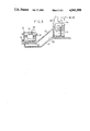
- FIG. 2 shows a method of mounting the heat exchanger on the chamber of a carburetor, in a modified embodiment of the invention
- FIG. 3 shows another embodiment.
- the fuel supply device partly shown in FIG. 1 comprises a carburetor, of which only the components concerned by the invention have been illustrated.
- the carburetor has a body in which is formed an induction passage 10 into which a main fuel jetting circuit opens through a passage 12.
- the main jetting circuit is fed with fuel from a constant level chamber 14 provided with a vent orifice 16.
- the chamber is connected to the main jetting circuit by a jet 18. It receives fuel from a tank 20 through a fuel pipe 22, a pump 24 and a duct 26.
- Duct 26 opens into chamber 14 through a seat 28 which can be closed by the needle 13 of a float 32. This arrangement makes it possible to maintain the free surface of the fuel in the chamber at a constant level N.
- the invention is also applicable to overflow constant level chambers.
- a heat exchanger through which a liquid flows is placed in thermal contact with the chamber.
- the heat exchanger is formed by a passage 40 formed in the wall of the casing defining the chamber.
- the passage may be formed during manufacture of the body of the carburetor, by casting.
- a liquid is circulated in closed circuit through the heat exchanger 40 when the temperature of the chamber exceeds a given value.
- the cooling liquid in the closed loop circuit is, for example, water contained in the windscreen washer reservoir 42 which is then given a volume greater than that which is usual (5 liters instead of 2 liters for example).
- the closed circuit comprises a circulating pump 44 whose inlet pipe 45 is immersed in the liquid, a delivery conduit from the pump to the exchanger 40 and a return duct 48 to the reservoir. It is preferable to provide the reservoir 42 with a sensor which lights a warning light on the dashboard of the vehicle when the level of water drops too much.
- Pump 44 is provided with a control circuit whose detector is a temperature sensor 50 in contact with the wall of the chamber and which may for example be a thermal switch which closes as soon as the temperature of the bottom wall of chamber 14 exceeds a predetermined limit value, for example between 40° C. and 60° C.
- a timer may also be provided for limiting the duration of operation of pump 44 from the instant the ignition switch is cut off.
- Operation is then as follows: if the temperature of the chamber of the carburetor becomes higher than a predetermined temperature, the thermal switch 50 closes. Pump 34 circulates water in the vicinity of the fuel contained in the chamber and thus avoids fuel evaporation and discharge into the intake pipe of the engine by percolation due to heat migrating from the hot engine.
- the system shown in FIG. 1 may be of very low cost if elements are used already existing in the vehicle, as for example those of a windscreen washer: the pump of the windscreen washer may even be used which should be completed by a valve normally closing the passage towards the windscreen and opening as soon as the windscreen washer is caused to operate. It is however more advantageous to provide a low cost additional pump.
- the temperature rise of the water of the windscreen washer caused by implementing the invention is of advantage since it will render cleaning of the windscreen of the vehicle more efficient.
- a special reservoir containing an antifreeze liquid may be provided and sealed so as to avoid having to fill it periodically.
- the heat exchanger may be placed against the chamber instead of being integrated in the wall thereof.
- the heat exchanger is formed as a liquid circulation box 38a, advantageously of heat conducting material (copper or brass, for example) welded to the bottom of the chamber so as to reduce the thermal impedance at the interface. It is even possible to provide two exchangers 38a and 40a side by side, one of which being swept by fuel fed to the float chamber, the other having liquid flowing therethrough in closed circuit.
- the cooling liquid flows through exchanger 52 by thermo-siphon effect.
- Exchanger 52 is connected by inlet and outlet lines 54, 56 to a reservoir of liquid 58 placed at a higher level, which may once again be the reservoir of the windscreen washer further having its usual pump 54. Circulation then takes place from the lower point of reservoir 58 to the exchanger 52 and from exchanger 52 to the higher point of the reservoir.
- An insulating wall 60 may provided between the windscreen washer and the engine to avoid heating of the liquid in the reservoir.
- An electric pump 62 may be provided for enhancing the flow when the temperature of the chamber, detected by a sensor (not shown), exceeds a predetermined value.
Landscapes
- Engineering & Computer Science (AREA)
- Chemical & Material Sciences (AREA)
- Combustion & Propulsion (AREA)
- Mechanical Engineering (AREA)
- General Engineering & Computer Science (AREA)
- Cooling, Air Intake And Gas Exhaust, And Fuel Tank Arrangements In Propulsion Units (AREA)
- Means For Warming Up And Starting Carburetors (AREA)
Abstract
Description
Claims (8)
Applications Claiming Priority (2)
| Application Number | Priority Date | Filing Date | Title |
|---|---|---|---|
| FR8803807 | 1988-03-23 | ||
| FR8803807A FR2629137A1 (en) | 1988-03-23 | 1988-03-23 | FUEL SUPPLY DEVICE WITH COOLED TANK |
Publications (1)
| Publication Number | Publication Date |
|---|---|
| US4941999A true US4941999A (en) | 1990-07-17 |
Family
ID=9364568
Family Applications (1)
| Application Number | Title | Priority Date | Filing Date |
|---|---|---|---|
| US07/322,290 Expired - Fee Related US4941999A (en) | 1988-03-23 | 1989-03-13 | Fuel supply device with cooled flow chamber |
Country Status (6)
| Country | Link |
|---|---|
| US (1) | US4941999A (en) |
| EP (1) | EP0334753B1 (en) |
| AR (1) | AR240188A1 (en) |
| BR (1) | BR8901497A (en) |
| DE (1) | DE68900696D1 (en) |
| FR (1) | FR2629137A1 (en) |
Cited By (9)
| Publication number | Priority date | Publication date | Assignee | Title |
|---|---|---|---|---|
| US5762040A (en) * | 1997-02-04 | 1998-06-09 | Brunswick Corporation | Cylinder wall fuel injection system for loop-scavenged, two-cycle internal combustion engine |
| US5791304A (en) * | 1997-02-13 | 1998-08-11 | Brunswick Corporation | Cylinder wall fuel injection system for cross-scavenged, two-cycle combustion engine |
| US5832903A (en) * | 1997-06-02 | 1998-11-10 | Brunswick Corp. | Fuel supply system for an internal combustion engine |
| US6092494A (en) * | 1998-01-27 | 2000-07-25 | Brunswick Corporation | Controlled pressure rise in two-cycle internal combustion engine having cylinder wall fuel injection |
| US6810661B2 (en) * | 2002-08-09 | 2004-11-02 | Ford Global Technologies, Llc | Method and system for freeze protecting liquid NOx reductants for vehicle application |
| US20060124113A1 (en) * | 2004-12-10 | 2006-06-15 | Roberts Forest G Sr | Marine engine fuel cooling system |
| US20080202473A1 (en) * | 2007-02-27 | 2008-08-28 | Ford Global Technologies Llc | Method and apparatus for rapidly thawing frozen nox reductant |
| US20110115106A1 (en) * | 2008-12-02 | 2011-05-19 | Tamotsu Saito | Diaphragm carburetor |
| WO2018075604A1 (en) | 2016-10-18 | 2018-04-26 | Sterilex LLC | Ambient moisture-activated surface treatment powder |
Families Citing this family (1)
| Publication number | Priority date | Publication date | Assignee | Title |
|---|---|---|---|---|
| FR2666122A1 (en) * | 1990-08-24 | 1992-02-28 | Renault | Fuel supply device for internal combustion engine |
Citations (12)
| Publication number | Priority date | Publication date | Assignee | Title |
|---|---|---|---|---|
| US1974586A (en) * | 1932-02-01 | 1934-09-25 | Bendix Aviat Corp | Carburetor |
| GB843582A (en) * | 1957-12-24 | 1960-08-04 | Sibe | Improvements in carburretors for internal combustion engines |
| US3196926A (en) * | 1962-05-28 | 1965-07-27 | Ford Motor Co | Fuel supply systems |
| FR2036327A5 (en) * | 1969-03-10 | 1970-12-24 | Peugeot & Renault | |
| US3882692A (en) * | 1973-06-13 | 1975-05-13 | Nissan Motor | Fuel cooling device in an automotive vehicle equipped with an air conditioner |
| US4036188A (en) * | 1974-07-18 | 1977-07-19 | Toyota Jidosha Kogyo Kabushiki Kaisha | Carburetor equipped with a cooling system |
| US4084564A (en) * | 1974-09-09 | 1978-04-18 | Borg-Warner Corporation | Heat exchanger system for charge forming apparatus |
| US4098236A (en) * | 1976-10-29 | 1978-07-04 | Toyota Jidosha Kogyo Kabushiki Kaisha | Device for supplying fuel to an internal combustion engine |
| JPS53146037A (en) * | 1977-05-26 | 1978-12-19 | Toyota Motor Corp | Controller for temperature of fuel in float chamber of carburetor of internal combustion engine |
| US4364355A (en) * | 1979-07-18 | 1982-12-21 | Hitachi, Ltd. | Electronically controlled fuel supply apparatus for internal combustion engine |
| DE8406706U1 (en) * | 1984-03-03 | 1985-09-05 | Audi AG, 8070 Ingolstadt | Carburetor of an internal combustion engine in a motor vehicle with a device for preventing the formation of vapor bubbles in the float chamber |
| US4715327A (en) * | 1986-05-23 | 1987-12-29 | Hale Fire Pump Company | Flow system for engine-pump assembly |
Family Cites Families (2)
| Publication number | Priority date | Publication date | Assignee | Title |
|---|---|---|---|---|
| JPS53117124A (en) * | 1977-03-22 | 1978-10-13 | Toyota Motor Corp | Engine fuel supply system device |
| JPS62253948A (en) * | 1986-04-25 | 1987-11-05 | Suzuki Motor Co Ltd | Cooling device for carburetor |
-
1988
- 1988-03-23 FR FR8803807A patent/FR2629137A1/en active Pending
-
1989
- 1989-02-13 AR AR313203A patent/AR240188A1/en active
- 1989-03-13 US US07/322,290 patent/US4941999A/en not_active Expired - Fee Related
- 1989-03-21 EP EP89400796A patent/EP0334753B1/en not_active Expired - Lifetime
- 1989-03-21 DE DE8989400796T patent/DE68900696D1/en not_active Expired - Fee Related
- 1989-03-22 BR BR898901497A patent/BR8901497A/en unknown
Patent Citations (13)
| Publication number | Priority date | Publication date | Assignee | Title |
|---|---|---|---|---|
| US1974586A (en) * | 1932-02-01 | 1934-09-25 | Bendix Aviat Corp | Carburetor |
| GB843582A (en) * | 1957-12-24 | 1960-08-04 | Sibe | Improvements in carburretors for internal combustion engines |
| US3196926A (en) * | 1962-05-28 | 1965-07-27 | Ford Motor Co | Fuel supply systems |
| FR2036327A5 (en) * | 1969-03-10 | 1970-12-24 | Peugeot & Renault | |
| US3628516A (en) * | 1969-03-10 | 1971-12-21 | Jean Louis Perrin | Internal combustion engine carburetor |
| US3882692A (en) * | 1973-06-13 | 1975-05-13 | Nissan Motor | Fuel cooling device in an automotive vehicle equipped with an air conditioner |
| US4036188A (en) * | 1974-07-18 | 1977-07-19 | Toyota Jidosha Kogyo Kabushiki Kaisha | Carburetor equipped with a cooling system |
| US4084564A (en) * | 1974-09-09 | 1978-04-18 | Borg-Warner Corporation | Heat exchanger system for charge forming apparatus |
| US4098236A (en) * | 1976-10-29 | 1978-07-04 | Toyota Jidosha Kogyo Kabushiki Kaisha | Device for supplying fuel to an internal combustion engine |
| JPS53146037A (en) * | 1977-05-26 | 1978-12-19 | Toyota Motor Corp | Controller for temperature of fuel in float chamber of carburetor of internal combustion engine |
| US4364355A (en) * | 1979-07-18 | 1982-12-21 | Hitachi, Ltd. | Electronically controlled fuel supply apparatus for internal combustion engine |
| DE8406706U1 (en) * | 1984-03-03 | 1985-09-05 | Audi AG, 8070 Ingolstadt | Carburetor of an internal combustion engine in a motor vehicle with a device for preventing the formation of vapor bubbles in the float chamber |
| US4715327A (en) * | 1986-05-23 | 1987-12-29 | Hale Fire Pump Company | Flow system for engine-pump assembly |
Cited By (14)
| Publication number | Priority date | Publication date | Assignee | Title |
|---|---|---|---|---|
| US5762040A (en) * | 1997-02-04 | 1998-06-09 | Brunswick Corporation | Cylinder wall fuel injection system for loop-scavenged, two-cycle internal combustion engine |
| US5791304A (en) * | 1997-02-13 | 1998-08-11 | Brunswick Corporation | Cylinder wall fuel injection system for cross-scavenged, two-cycle combustion engine |
| US5832903A (en) * | 1997-06-02 | 1998-11-10 | Brunswick Corp. | Fuel supply system for an internal combustion engine |
| US6092494A (en) * | 1998-01-27 | 2000-07-25 | Brunswick Corporation | Controlled pressure rise in two-cycle internal combustion engine having cylinder wall fuel injection |
| US6810661B2 (en) * | 2002-08-09 | 2004-11-02 | Ford Global Technologies, Llc | Method and system for freeze protecting liquid NOx reductants for vehicle application |
| US20060124113A1 (en) * | 2004-12-10 | 2006-06-15 | Roberts Forest G Sr | Marine engine fuel cooling system |
| US20080202473A1 (en) * | 2007-02-27 | 2008-08-28 | Ford Global Technologies Llc | Method and apparatus for rapidly thawing frozen nox reductant |
| US7930878B2 (en) | 2007-02-27 | 2011-04-26 | Ford Global Technologies, Llc | Method and apparatus for rapidly thawing frozen NOx reductant |
| US20110120984A1 (en) * | 2007-02-27 | 2011-05-26 | Ford Global Technologies Llc | Method and Apparatus for Rapidly Thawing Frozen NOx Reductant |
| US8534054B2 (en) | 2007-02-27 | 2013-09-17 | Ford Global Technologies, Llc | Method and apparatus for rapidly thawing frozen NOx reductant |
| US20110115106A1 (en) * | 2008-12-02 | 2011-05-19 | Tamotsu Saito | Diaphragm carburetor |
| US8308144B2 (en) * | 2008-12-02 | 2012-11-13 | Zama Japan Kabushiki Kaisha | Diaphragm carburetor |
| US8632057B2 (en) * | 2008-12-02 | 2014-01-21 | Zama Japan Kabushiki Kaisha | Diaphragm carburetor |
| WO2018075604A1 (en) | 2016-10-18 | 2018-04-26 | Sterilex LLC | Ambient moisture-activated surface treatment powder |
Also Published As
| Publication number | Publication date |
|---|---|
| AR240188A1 (en) | 1990-02-28 |
| EP0334753A1 (en) | 1989-09-27 |
| BR8901497A (en) | 1989-11-14 |
| DE68900696D1 (en) | 1992-02-27 |
| EP0334753B1 (en) | 1992-01-15 |
| FR2629137A1 (en) | 1989-09-29 |
Similar Documents
| Publication | Publication Date | Title |
|---|---|---|
| US4941999A (en) | Fuel supply device with cooled flow chamber | |
| US4748960A (en) | Fuel system | |
| US5662072A (en) | Engine warming-up apparatus for a vehicle and heat insulating device | |
| JPH071005B2 (en) | Refrigerant circuit for internal combustion engine | |
| US4932365A (en) | System for evaporation cooling of an internal combustion engine and for operation of a heating heat exchanger by the coolant | |
| US3788283A (en) | Dual fuel system | |
| EP0126422A2 (en) | Improved cooling system for automotive engine or the like | |
| US3477238A (en) | Thermoelectric antipercolator device for the fuel system of an internal combustion engine | |
| JPH0544462A (en) | Evaporative cooling type internal combustion engine | |
| EP0119246A4 (en) | Method and system for preheating fuel. | |
| JPH073172B2 (en) | Boiling cooling device for internal combustion engine | |
| US4677942A (en) | Cooling system for automotive engine or the like | |
| US4499032A (en) | System for preventing the percolation of fuel in a carburetor | |
| EP0176985B1 (en) | Cabin heating arrangement for vehicle having evaporative cooled engine | |
| US3048157A (en) | Air pollution abatement system | |
| US2290300A (en) | Automobile heater | |
| US3845464A (en) | Low coolant indicator | |
| US4432328A (en) | Vapor lock and percolation phenomena inhibiting system | |
| CN108386300A (en) | heavy truck fuel supply device | |
| US4403590A (en) | Engine fuel consumption reduction system | |
| US4681179A (en) | Cooling system for use in cab-over type vehicles | |
| EP0153730B1 (en) | Passenger room heating system for use with boiling liquid engine cooling system | |
| US2963013A (en) | Anti-vapor lock device | |
| US2054525A (en) | Apparatus for starting internal combustion engines | |
| JPS5848767A (en) | Operation control system for electric fuel pump for engine |
Legal Events
| Date | Code | Title | Description |
|---|---|---|---|
| AS | Assignment |
Owner name: SOLEX,, FRANCE Free format text: ASSIGNMENT OF ASSIGNORS INTEREST.;ASSIGNOR:NOISIER, GUY;REEL/FRAME:005054/0175 Effective date: 19890602 |
|
| FEPP | Fee payment procedure |
Free format text: PAYOR NUMBER ASSIGNED (ORIGINAL EVENT CODE: ASPN); ENTITY STATUS OF PATENT OWNER: LARGE ENTITY |
|
| FEPP | Fee payment procedure |
Free format text: PAYER NUMBER DE-ASSIGNED (ORIGINAL EVENT CODE: RMPN); ENTITY STATUS OF PATENT OWNER: LARGE ENTITY Free format text: PAYOR NUMBER ASSIGNED (ORIGINAL EVENT CODE: ASPN); ENTITY STATUS OF PATENT OWNER: LARGE ENTITY |
|
| FPAY | Fee payment |
Year of fee payment: 4 |
|
| REMI | Maintenance fee reminder mailed | ||
| LAPS | Lapse for failure to pay maintenance fees | ||
| FP | Lapsed due to failure to pay maintenance fee |
Effective date: 19980722 |
|
| STCH | Information on status: patent discontinuation |
Free format text: PATENT EXPIRED DUE TO NONPAYMENT OF MAINTENANCE FEES UNDER 37 CFR 1.362 |