US4935810A - Three-dimensional measuring apparatus - Google Patents
Three-dimensional measuring apparatus Download PDFInfo
- Publication number
- US4935810A US4935810A US07/376,460 US37646089A US4935810A US 4935810 A US4935810 A US 4935810A US 37646089 A US37646089 A US 37646089A US 4935810 A US4935810 A US 4935810A
- Authority
- US
- United States
- Prior art keywords
- object point
- point
- displaying
- designating
- image
- Prior art date
- Legal status (The legal status is an assumption and is not a legal conclusion. Google has not performed a legal analysis and makes no representation as to the accuracy of the status listed.)
- Expired - Lifetime
Links
Images


Classifications
-
- G—PHYSICS
- G01—MEASURING; TESTING
- G01B—MEASURING LENGTH, THICKNESS OR SIMILAR LINEAR DIMENSIONS; MEASURING ANGLES; MEASURING AREAS; MEASURING IRREGULARITIES OF SURFACES OR CONTOURS
- G01B11/00—Measuring arrangements characterised by the use of optical techniques
- G01B11/02—Measuring arrangements characterised by the use of optical techniques for measuring length, width or thickness
-
- A—HUMAN NECESSITIES
- A61—MEDICAL OR VETERINARY SCIENCE; HYGIENE
- A61B—DIAGNOSIS; SURGERY; IDENTIFICATION
- A61B1/00—Instruments for performing medical examinations of the interior of cavities or tubes of the body by visual or photographical inspection, e.g. endoscopes; Illuminating arrangements therefor
- A61B1/00163—Optical arrangements
- A61B1/00193—Optical arrangements adapted for stereoscopic vision
-
- A—HUMAN NECESSITIES
- A61—MEDICAL OR VETERINARY SCIENCE; HYGIENE
- A61B—DIAGNOSIS; SURGERY; IDENTIFICATION
- A61B1/00—Instruments for performing medical examinations of the interior of cavities or tubes of the body by visual or photographical inspection, e.g. endoscopes; Illuminating arrangements therefor
- A61B1/00163—Optical arrangements
- A61B1/00194—Optical arrangements adapted for three-dimensional imaging
-
- A—HUMAN NECESSITIES
- A61—MEDICAL OR VETERINARY SCIENCE; HYGIENE
- A61B—DIAGNOSIS; SURGERY; IDENTIFICATION
- A61B5/00—Measuring for diagnostic purposes; Identification of persons
- A61B5/103—Measuring devices for testing the shape, pattern, colour, size or movement of the body or parts thereof, for diagnostic purposes
- A61B5/107—Measuring physical dimensions, e.g. size of the entire body or parts thereof
- A61B5/1076—Measuring physical dimensions, e.g. size of the entire body or parts thereof for measuring dimensions inside body cavities, e.g. using catheters
-
- G—PHYSICS
- G06—COMPUTING OR CALCULATING; COUNTING
- G06F—ELECTRIC DIGITAL DATA PROCESSING
- G06F3/00—Input arrangements for transferring data to be processed into a form capable of being handled by the computer; Output arrangements for transferring data from processing unit to output unit, e.g. interface arrangements
- G06F3/01—Input arrangements or combined input and output arrangements for interaction between user and computer
- G06F3/048—Interaction techniques based on graphical user interfaces [GUI]
- G06F3/0481—Interaction techniques based on graphical user interfaces [GUI] based on specific properties of the displayed interaction object or a metaphor-based environment, e.g. interaction with desktop elements like windows or icons, or assisted by a cursor's changing behaviour or appearance
- G06F3/04812—Interaction techniques based on cursor appearance or behaviour, e.g. being affected by the presence of displayed objects
-
- G—PHYSICS
- G06—COMPUTING OR CALCULATING; COUNTING
- G06F—ELECTRIC DIGITAL DATA PROCESSING
- G06F3/00—Input arrangements for transferring data to be processed into a form capable of being handled by the computer; Output arrangements for transferring data from processing unit to output unit, e.g. interface arrangements
- G06F3/01—Input arrangements or combined input and output arrangements for interaction between user and computer
- G06F3/048—Interaction techniques based on graphical user interfaces [GUI]
- G06F3/0484—Interaction techniques based on graphical user interfaces [GUI] for the control of specific functions or operations, e.g. selecting or manipulating an object, an image or a displayed text element, setting a parameter value or selecting a range
- G06F3/04842—Selection of displayed objects or displayed text elements
-
- G—PHYSICS
- G06—COMPUTING OR CALCULATING; COUNTING
- G06T—IMAGE DATA PROCESSING OR GENERATION, IN GENERAL
- G06T7/00—Image analysis
- G06T7/50—Depth or shape recovery
- G06T7/55—Depth or shape recovery from multiple images
- G06T7/593—Depth or shape recovery from multiple images from stereo images
-
- H—ELECTRICITY
- H04—ELECTRIC COMMUNICATION TECHNIQUE
- H04N—PICTORIAL COMMUNICATION, e.g. TELEVISION
- H04N13/00—Stereoscopic video systems; Multi-view video systems; Details thereof
- H04N13/10—Processing, recording or transmission of stereoscopic or multi-view image signals
- H04N13/106—Processing image signals
- H04N13/156—Mixing image signals
-
- H—ELECTRICITY
- H04—ELECTRIC COMMUNICATION TECHNIQUE
- H04N—PICTORIAL COMMUNICATION, e.g. TELEVISION
- H04N13/00—Stereoscopic video systems; Multi-view video systems; Details thereof
- H04N13/20—Image signal generators
- H04N13/204—Image signal generators using stereoscopic image cameras
- H04N13/239—Image signal generators using stereoscopic image cameras using two two-dimensional [2D] image sensors having a relative position equal to or related to the interocular distance
-
- H—ELECTRICITY
- H04—ELECTRIC COMMUNICATION TECHNIQUE
- H04N—PICTORIAL COMMUNICATION, e.g. TELEVISION
- H04N13/00—Stereoscopic video systems; Multi-view video systems; Details thereof
- H04N13/20—Image signal generators
- H04N13/275—Image signal generators from three-dimensional [3D] object models, e.g. computer-generated stereoscopic image signals
-
- H—ELECTRICITY
- H04—ELECTRIC COMMUNICATION TECHNIQUE
- H04N—PICTORIAL COMMUNICATION, e.g. TELEVISION
- H04N13/00—Stereoscopic video systems; Multi-view video systems; Details thereof
- H04N13/30—Image reproducers
- H04N13/332—Displays for viewing with the aid of special glasses or head-mounted displays [HMD]
- H04N13/344—Displays for viewing with the aid of special glasses or head-mounted displays [HMD] with head-mounted left-right displays
-
- G—PHYSICS
- G06—COMPUTING OR CALCULATING; COUNTING
- G06T—IMAGE DATA PROCESSING OR GENERATION, IN GENERAL
- G06T2207/00—Indexing scheme for image analysis or image enhancement
- G06T2207/10—Image acquisition modality
- G06T2207/10004—Still image; Photographic image
- G06T2207/10012—Stereo images
-
- H—ELECTRICITY
- H04—ELECTRIC COMMUNICATION TECHNIQUE
- H04N—PICTORIAL COMMUNICATION, e.g. TELEVISION
- H04N13/00—Stereoscopic video systems; Multi-view video systems; Details thereof
- H04N13/10—Processing, recording or transmission of stereoscopic or multi-view image signals
-
- H—ELECTRICITY
- H04—ELECTRIC COMMUNICATION TECHNIQUE
- H04N—PICTORIAL COMMUNICATION, e.g. TELEVISION
- H04N13/00—Stereoscopic video systems; Multi-view video systems; Details thereof
- H04N13/10—Processing, recording or transmission of stereoscopic or multi-view image signals
- H04N13/106—Processing image signals
- H04N13/167—Synchronising or controlling image signals
-
- H—ELECTRICITY
- H04—ELECTRIC COMMUNICATION TECHNIQUE
- H04N—PICTORIAL COMMUNICATION, e.g. TELEVISION
- H04N13/00—Stereoscopic video systems; Multi-view video systems; Details thereof
- H04N13/10—Processing, recording or transmission of stereoscopic or multi-view image signals
- H04N13/189—Recording image signals; Reproducing recorded image signals
-
- H—ELECTRICITY
- H04—ELECTRIC COMMUNICATION TECHNIQUE
- H04N—PICTORIAL COMMUNICATION, e.g. TELEVISION
- H04N13/00—Stereoscopic video systems; Multi-view video systems; Details thereof
- H04N13/10—Processing, recording or transmission of stereoscopic or multi-view image signals
- H04N13/194—Transmission of image signals
-
- H—ELECTRICITY
- H04—ELECTRIC COMMUNICATION TECHNIQUE
- H04N—PICTORIAL COMMUNICATION, e.g. TELEVISION
- H04N13/00—Stereoscopic video systems; Multi-view video systems; Details thereof
- H04N13/20—Image signal generators
- H04N13/286—Image signal generators having separate monoscopic and stereoscopic modes
-
- H—ELECTRICITY
- H04—ELECTRIC COMMUNICATION TECHNIQUE
- H04N—PICTORIAL COMMUNICATION, e.g. TELEVISION
- H04N13/00—Stereoscopic video systems; Multi-view video systems; Details thereof
- H04N2013/0074—Stereoscopic image analysis
- H04N2013/0081—Depth or disparity estimation from stereoscopic image signals
Definitions
- This invention relates to a three-dimensional measuring apparatus for measuring an inspected object in relation to its three-dimensional positioin.
- the inspected part is plane and the unevenness is hard to recognize. Therefore, for example, in the publication of a Japanese patent application laid open No. 24215/1989 is disclosed an apparatus wherein two systems of objective lenses are provided in the tip part of an endoscope so that two picture images obtained by these two systems of objective lenses may be led to an eyepiece part through an image guide to obtain a cubic visual field by binoculars. Also, in the publication of a Japanese patent application laid open No. 46927/1983 is disclosed a stereo-visible endoscope provided in the tip part with two imaging optical systems and two solid state imaging devices.
- the size of the object can be numerically known as described above, on the other hand, it is desired to directly know the size of the object by sight.
- An object of the present invention is to provide a three-dimensional measuring apparatus whereby the designation of respective object points on a plurality of images having parallaxes to specify measuring object points in the space is made easy.
- Another object of the present invention is to provide a three-dimensional measuring apparatus whereby respective object points on a plurality of images having parallaxes can be accurately designated to specify measuring object points in the space.
- Another object of the present invention is to provide a three-dimensional measuring apparatus whereby respective object points on a plurality of images having parallaxes can be easily designated by one designating means to specify measuring object points in the space.
- Another object of the present invention is to provide a three-dimensional measuring apparatus whereby the size of the object can be known by sight.
- the three-dimensional measuring apparatus of the present invention comprises an imaging means imaging a plurality of images having parallaxes, a displaying means displaying on a plurality of pictures the plurality of images obtained by the above mentioned imaging means, a first object point designating means designating a first object point corresponding to the measuring object point in the space on the first image among a plurality of images displayed by the above mentioned displaying means, a second object point designating means designating a second object point corresponding to the above mentioned measuring object point in the space on the second image among the plurality of images displayed by the above mentiioned displaying means, an object point designating auxiliary means making an auxiliary process relating to the second object point designation by the above mentioned second object point designating means after the first object point designation by the above mentioned first object point designating means and an operating means making a measuring operation relating to the three-dimensional position of the above mentioned measuring object point specified by the first object point designated by the above mentioned first object point designating means and the second object point designated by the above mentioned second object point designating means
- FIGS. 1 to 5 relate to the first embodiment of the present invention.
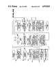
- FIG. 1 is a block diagram showing the formation of a measuring endoscope apparatus of the present invention.
- FIG. 2 is a view showing a tip part of a cubic endoscope image take-in apparatus.
- FIG. 3 is a view showing an operating panel of a cursor information designating means.
- FIG. 4 is a view showing an example of an operating picture.
- FIG. 5 is an explanatory view of a method of calculating the position of a guide line and the position of an object point.
- FIGS. 6 to 25 relate to the second embodidment of the present invention.
- FIG. 6 is a block diagram showing the schematic formation of this embodiment.
- FIG. 7 is an explanatory view of the tip part of an insertable part of an endoscope.
- FIG. 8 is a block diagram showing the formation of a measuring endoscope apparatus.
- FIG. 9 is a block diagram showing the formation of a host computer.
- FIG. 10 is a principle explaining view showing a method of determining a guide line.
- FIG. 11 is a principle explaining view showing a method of determining a three-dimensional coordinate.
- FIG. 12 is a principle explaining view showing a method of determining an index circle.
- FIG. 13 is an explanatory view for explaining the exchange of the position on a picture and the position on an imaging device.
- FIG. 14 is an explanatory view showing a guide line displayed in the left picture.
- FIG. 15 is an explanatory view showing an index circle displayed in the right picture.
- FIGS. 16 to 25 are flow charts for explaining the operation of this embodiment.
- FIGS. 26 and 27 are flow charts for explaining the operation of the first modification of the second embodiment.
- FIGS. 28 and 29 are flow charts for explaining the operation of the second modification of the second embodiment.
- FIGS. 30 to 37 relate to the third modification of the second embodiment.
- FIG. 30 is a principle explaining view of a distortion aberration correction.
- FIG. 31 is an explanatory view showing a guide line displayed in the left picture.
- FIG. 32 is an explanatory view showing an index circle displayed in the right picture.
- FIGS. 33 to 37 are flow charts for explaining the operation of this embodiment.
- FIGS. 38 and 39 are flow charts for explaining the operation of the fourth modification of the second embodiment.
- FIG. 40 is a flow chart for explaining the operation of the fifth modification of the second embodiment.
- FIG. 41 is a flow chart for explaining the operation of the sixth modification of the second embodiment.
- FIGS. 42 to 49 relate to the third embodiment of the present invention.
- FIG. 42 is a block diagram showing the schematic formation of this embodiment.
- FIG. 43 is a block diagram showing the formation of a measuring endoscope apparatus.
- FIG. 44 is a block diagram showing the formation of a host computer.
- FIGS. 45 to 49 are flow charts for explaining the operation of this embodiment.
- FIG. 50 is a flow chart for explaining the operation of the fourth embodiment.
- FIG. 51 is an explanatory view showing the position designation of a measuring object point in a measuring endoscope apparatus of a related art example.
- FIGS. 1 to 5 The first embodiment of the present invention is shown in FIGS. 1 to 5.
- the measuring endoscope apparatus of this embodiment is provided with a cubic endoscope image take-in apparatus 1 which has an elongate insertable part 1a.
- image forming optical systems 21 and 22 are provided in the tip part of this insertable part 1a.
- Such solid state imaging devices 23 and 24 as CCD's as imaging means are provided respectively in the image forming positions of these image forming optical systems 21 and 22.
- the light reflected from an object of the illuminating light emitted from an illuminating means not illustrated is made to form images by the above mentioned image forming optical systems 21 and 22 and the images are photoelectrically converted by the above mentioned solid state imaging devices 23 and 24 and are output respectively as left (L) and right (R) electric image signals which are digital-converted respectively by A/D converters 2L and 2R and are then memorized respectively in image memories 5L and 5R.
- synchronizing signals are fed to write-in timing controlling means 3L and 3R which feed write-in timing controlling signals to write-in controlling means 4L and 4R on the basis of these synchronizing signals.
- write-in controlling means 4L and 4R By the control signals from these write-in controlling means 4L and 4R, the writing of the image signals into the above mentioned memories 5L and 5R from the above mentioned A/D converters 2L and 2R are controlled.
- the measuring endoscope apparatus of this embodiment is provided also with a cursor information indicating means 6 as a measuring object point designating means for indicating the information relating to the position of the cursor in the image.
- the cursor position information is fed from this cursor information indicating means 6 to a cursor controlling means 7 as an operating means and guide line displaying means.
- This cursor controlling means 7 is formed of a CPU having a calculating function, the displaying position of the cursor on the picture is calculated from the above mentioned cursor position information, the positions to display the points on the picture forming the cursor are housed in address designating means 8L and 8R, the colors to be written in are housed in data holding means 9L and 9R and further whether the cursor is on the guide line or not is judged.
- the outputs of the above mentioned address designating means 8 and data holding means 9L and 9R are memorized in graphic memeories 11L and 11R which are memories holding cursor images respectively on the left and right pictures and have a memorizing capacity of 3 bits per pixel if the kinds of the colors of the cursors are three kinds.
- the images of the cursors held by these graphic memories 11L and 11R will be renewed when the data of the colors read out of the above mentioned data holding means 9L and 9R are written into the coordinate positions on the picture read out of the above mentioned address designating means 8L and 8R during the vertical flyback line period or horizontal flyback line period of the synchronizing signals from read-out controlling means 13L and 13R.
- Read-out synchronizing signals from a read-out synchronizing signal generating means 12 are applied to the above mentioned read-out controlling means 13L and 13R.
- Synchronizing signals for synchronizing and reading out data corresponding to the same picture positions from the respective memories for the above mentioned image memories 5L and 5R and graphic memories 11L and 11R on the basis of these synchronizing signals are fed to these read-out controlling means 13.
- the respective data read out of the above mentioned image memories 5L and 5R and graphic memories 11L and 11R are input into logical sum operators 14L and 14R.
- logical sum operators 14L and 14R a logical sum of the data output from the above mentioned image memories 5L and 5R and the data output from the above mentioned graphic memories 11L and 11R is calculated and the results are output to D/A converters 15L and 15R.
- Digital type image signals are converted to analogue type video signals by these D/A converters 15L and 15R and images are displayed in image displaying apparatus 16L and 16R as displaying means.
- the measuring endoscope apparatus of this embodiment is further provided with a cursor position memorizing means 17 memorizing a plurality of cursor positions in a cubic image when a memory is indicated by the above mentioned cursor information designating means 6 and a distance operating means 18 as a distance calculating means reading out the cursor positions memorized by this cursor position memorizing means 17 by the indication of the distance operation from the above mentioned cursor information designating means 6, operating the distances between the respective cursor positions and outputting the results to a displaying apparatus not illustrated.
- a cursor position memorizing means 17 memorizing a plurality of cursor positions in a cubic image when a memory is indicated by the above mentioned cursor information designating means 6
- a distance operating means 18 as a distance calculating means reading out the cursor positions memorized by this cursor position memorizing means 17 by the indication of the distance operation from the above mentioned cursor information designating means 6, operating the distances between the respective cursor positions and outputting the results to a displaying apparatus not illustrated.
- the left and right image signals from the cubic endoscope image take-in apparatus 1 are digital-converted respectively by the A/D converters 2L and 2R and are then memorized in the image memories 5L and 5R.
- the image signals memorized in these image memories 5L and 5R are read out usually at a real time, have logical sums operated by the logical sum operators 14L and 14R and are converted to analogue type signals by the D/A converters 15L and 15R and then images are displayed in the displaying apparatus.
- the object intended to be measured by the operator is contained within the visual field, in order to prevent the lag of the position designation by the motion within the living body, first the images to be memorized by the above mentioned image memories 5L and 5R are stilled. Then the cursor within the left image is moved to the position of the object point to be measured in the length by the cursor information designating means 6 having an operating panel formed as shown in FIG. 3. The state of the picture of the displaying apparatus 15 at this time will be such as is shown in FIG. 4(A). The position of the cursor can be moved by operating a cursor moving switch provided in the above mentioned cursor information designating means 6. Next, the position of the object point is memorized by pushing a selecting switch provided within the above mentioned cursor information designating means 6.
- the thus selected object point has the selected position displayed on the picture as shown in FIG. 4(B) to make the position definite.
- the cursor controlling means 7 designates the position of the guide line by the later described method from the position of the designated object and displays it in the right image.
- the state of the picture in the image in the displaying apparatus 16 at this time is shown in FIG. 4(C).
- the operator selects the position of the object point in the right image by the same operation. At this time, only the point on the guide line can be designated.
- the above mentioned cursor controlling means 7 checks whether the position of the selected point is already in the calculated positiion of the guide line. If the position of the selected point is not in the position of the guide line, a warning sound will be issued by a warning apparatus not illustrated and the selection will be made ineffective.
- the point on the guide line is selected, the position of the object point in the space will be defined and therefore this position will be calculated by the later described method and will be memorized.
- the state on the picture of the displaying apparatus 16 at this time is shown in FIG. 4(C).
- the position of the point measured in the length by repeating such operation is memorized and then the distances between the respective designated points are displayed in a displaying apparatus not illustrated by pushing a length measuring switch.
- the coordinates of the two points at this time are represented by (x 1 , y 1 , z 1 ) and (x 2 , y 2 , z 2 )
- the distance d between the two points will be given by the following formula:
- the distance from the tip of the insertable part to a certain point can be determined in the same manner.
- the center of the coordinates in the space shall be the intermediate point of both right and left imaging means
- the direction of the X axis shall be the direction passing through the centers of both right and left imaging means
- the direction of the Z axis shall be the vertical direction from the tip surface of the endoscope apparatus
- the direction of the Y axis shall be the direction intersecting at right angles with either of the X axis and Z axis.
- the parallax shall be d.
- the center of the left imaging means shall be represented by LC (-d/2, 0, 0), the center of the right imaging means shall be represented by RC(d/2, 0, 0), the position of the object point shall be represented by A(xa, ya, za), the focal distance shall be represented by f and the position of the object in the designated left image shall be represented by LP(x1, y1, f).
- t represents a parameter: ##EQU1##
- the guide line will be from the left end of the picture to the point corresponding to (x 1 +d, y 1 , -f).
- the position of the guide line and the position of the object point can be calculated.
- a measuring object point when a measuring object point is designated on one picture, how a straight line in the space passing through the imaging means having imaged the picture and this measuring object point should appear to the other imaging means will be operated and the straight line will be displayed as a guide line on the other picture. Further, as the other points than the point on this guide line can not be designated as object points, the position of the object point can be accurately designated and thereby the distance and length can be accurately measured.
- respective displaying apparatus are provided on the right and left images but one displaying apparatus may be provided to display both right and left images in one displaying apparatus.
- FIGS. 6 to 25 The second embodiment of the present invention is shown in FIGS. 6 to 25.
- the measuring endoscope apparatus of this embodiment comprises a stereo type video image endoscope (which shall be mentioned as an endoscope hereinafter) 101, a right image video processor 110R and left image video processor 110L respectively processing the image signals of a right image and left image imaged by this endoscope 101, a right image frame memory 112R and left image frame memory 112L respectively memorizing image signals, for example, by RGB signals output from the above mentioned respective video processors 110R and 110L, a right image monitor 130R and left image monitor 130L inputting image signals, for example, by RGB signals output from the above mentioned respective frame memories 112R and 112L and displaying respectively a right image and left image, a host computer 120 operating cubic measurement by using the images memorized in the above mentioned respective frame memories 112R and 112L, an external memorizing apparatus (which shall be mentioned as an external memory hereinafter) 140 connected to the above mentioned host computer and a mouse 145 connected to the above mentioned host computer 120, operating the cursors displayed in the above mentioned monitor
- the above mentioned video processors 110R and 110L process signals synchronized with each other.
- the above mentioned respective frame memories 112R and 112L are provided respectively with a plurality of sets of respective memories of R, G and B, images are memorized in one set, cursors are written into the other set and the images and cursors can be displayed on the picture of a monitor by adding together the signals written into the respective sets.
- the above mentioned external memory 140 can memorize the images in the frame memories 112R and 112L and can memorize a large amount of images as an image file.
- the above mentioned host computer 120 is formed as shown in FIG. 9.
- the host computer 120 comprises a CPU 121, right frame memory interface 122R, left frame memory interface 122L, main memory 123, external memory interface 124, mouse interface 125, keyboard 126 and CRT 127.
- the above mentioned right frame memory interface 122R and left frame memory interface 122L are connected respectively to the above mentioned right image frame memory 112R and left image frame memory L12 so that image data may be transmitted and received between them and the cursors for the above mentioned frame memories 112R and 112L may be controlled through the respective interfaces 122R and 122L.
- the above mentioned external memory interface 124 is connected to the external memory 140 to transmit and receive image data.
- the above mentioned mouse interface 125 is connected to the mouse 145.
- the endoscope 101 is provided with an elongate insertable part 102 and a plurality of, for example, two observing windows and illuminating windows are provided in the tip part of this insertable part 102.
- a right eye objective lens system 103R and left eye objective lens system 103L are provided in the positions having parallaxes with each other inside the above mentioned respective observing windows.
- Imaging means 104R and 104L using solid state imaging devices are arranged respectively in the image forming positions of the respective objective lens systems 103R and 103L.
- a light distributing lens 105 is provided inside the above mentioned illuminating window.
- a light guide 106 consisting of a fiber bundle is provided as connected to the rear end of this light distributing lens 105.
- This light guide 106 is inserted through the above mentioned insertable part 102 and is connected at the entrance end to a light source apparatus not illustrated.
- the illuminating light output from this light source apparatus is radiated to an object through the above mentioned light guide 106 and light distributing lens 105.
- the light from this object is made to form a right image and left image respectively on the imaging means 104R and 104L by the above mentioned objective lens systems 103R and 103L.
- the respective image signals imaged by the above mentioned imaging means 104R and 104L are input respectively into video processors 110R and 110L and are processed to be video signals.
- the respective image signals output from the above mentioned respective video processors 110R and 110L are converted to digital signals respectively by A/D converters 111R and 111L and are then memorized in image memories, that is, in the image memories of respective frame memories 112R and 112L.
- the image signals read out of the above mentioned image memories 112R and 112L are respectively converted to analogue signals by D/A converters 158R and 158L through OR gates 157R and 157L and are input respectively into monitors 130R and 130L in which the right image and left image are respectively displayed.
- a cursor displaying means 151R displaying a cursor in the right picture and a cursor displaying means 151L displaying a cursor in the left picture are provided.
- a mouse 145 is connected to one of the above mentioned cursor displaying means 151R and 151L through a switching means 150 so that such operation as moving the cursors for the respective pictures may be made.
- the cursor displaying signals output from the above mentioned cursor displaying means 151R and 151L are input respectively into the above mentioned OR gates 157R and 157L so that the cursors may be superimposed on the pictures of the monitors 130R and 130L.
- a guide line displaying means 153 is connected to the right picture cursor displaying means 151R so that, in case the object point is designated in the right picture, the position condition on the left picture for the object point may be operated and a guide line displaying signal may be output on the basis of the position condition.
- This guide line displaying signal is input into an OR gate 157L so that the guide line may be displayed as superimposed on the picture of the left image monitor 130.
- An object point position calculating means 154 is connected to the above mentioned both cursor displaying means 151R and 151L so that, in case the object points are designated in both pictures, the three-dimensional coordinate of the measuring object point in the space may be determined from the coordinates in the respective pictures of the object points. Further, the above mentioned object point position calculating means 154 and right image cursor displaying means 151 are connected to an index circle displaying means 155 which outputs a signal for displaying an index circle to be a criterion of the size of the object by the three-dimensional coordinate of the above stipulated measuring object point and the position information of the object point in the right picture. This index circle displaying signal is input into an OR gate 157R so that the index circle may be displayed as superimposed on the picture of the image monitor 130R.
- the above mentioned switching means 150, cursor displaying means 151R and 151L, guide line displaying means 153, object point position calculating means 154 and index circle displaying means 155 are attained by operating the above mentioned host computer 120 by the later described procedure.
- the image (moving picture) is frozen (stilled) at a proper timing while being seen to fix the images on the frame memories 112R and 112L.
- a freely moving cursor (mentioned as a moving cursor hereinafter) for designating the point will appear in the right picture.
- the mouse 145 is operated to move the moving cursor onto a point desired to be designated.
- a guide line is displayed in the left picture.
- the mouse 145 is operated to move the moving cursor onto a point desired to be designated.
- the designated point is confirmed by using the mouse 145.
- the three-dimensional coordinate of the designated measuring object point is operated and output.
- the distance from the endoscope tip to the measuring object point is operated and output. By the way, this distance is displayed, if necessary.
- a circle fitted point is designated.
- the circle fitted point is a measuring object point designated to display the index circle.
- the point 1 in the above mentioned (3) 1 to 16 may be re-read a circle fitted point.
- An index circle to be a criterion of the size is displayed on the right image on the basis of the input radius and the three-dimensional coordinate of the circle fitted point.
- step S1-1 (hereinafter the "step” shall be omitted and merely like “S1-1” shall be mentioned), it is judged whether the image to be measured is an image from the endoscope or not.
- the negative case hereinafter the negative case shall be mentioned as "NO” and the affirmative case shall be mentioned as "YES"
- S1-2 it is judged whether the image to be measured is a image from the file or not.
- NO in S1-3, it is judged whether the operation ends or not.
- YES the process ends.
- the above mentioned S1-1 to S1-3 are repeated until the image from the endoscope or the image from the external memory is selected or the end of the process is indicated.
- the S1-1 and S1-2 may be in any order
- S3-2 to S3-7 may be in any order.
- S4-2 to S4-6 are exactly the same as the S3-2 to S3-6 in the above mentioned freeze (). That is to say, it is judged whether the point 1 is designated or not, the point 2 is designated or not, the circle fitted point is designated or not, the point is released or not and the circle fitted point is released or not.
- S4-11 to S4-15 which are the same as S3-11 to S3-15 in the above mentioned freeze () are made and the process returns to the above mentioned S4-2.
- S4-2 to S4-7 may be in any order.
- Rmovecur is a routine designating the point in the right picture to obtain the x and y coordinates (S -- Rx1, S -- Ry1) of the designated point. This Rmovecur is shown in FIG. 22.
- Lguide is a routine of drawing a guide line on the left picture on the basis of the x and y coordinates (S -- Rx1, S -- Ry1) of the designated point in the right picture and is shown in FIG. 23.
- Lmovecur is a routine designating the point in the left picture to obtain the x and y coordinates (S -- Lx1, S -- LY1) of the designated point.
- 3dpoint () a sub-routine called "3dpoint ()" is made by making arguments the x and y coordinates (S -- Rx1, S -- Ry1, S -- Lx1, S -- Ly1) of the designated points in the respective right and left pictures.
- This 3dpoint is a routine calculating the three-dimensional coordinates of the measuring object points (points 1) corresponding to the two designated points on the basis of the designated points in the respective right and left pictures. The results are attributed to (S -- x1, S --y1 ).
- This 3dpoint () is shown in FIG. 24.
- the distance to the point 1 is calculated by using the above mentioned three-dimensional coordinate (S -- x1, S -- y1, S -- z1).
- the point 1 is designated in the right picture, thereby the guide line is displayed on the left picture and the point 1 in the left picture is designated on the guide line.
- the three-dimensional coordinate of the point 1 is calculated and, if the point 2 is designated, the distance between the points 1 and 2 is calculated.
- the three-dimensional coordinate of the above mentioned point 1 and the distance between the points 1 and 2 may be displayed as required.
- the point 2 is not illustrated but is basically the same as the above mentioned point 1 () and has the description (including the coordinates) relating to the points 1 and 2 replaced.
- a sub-routine called "3dpoint ()" is made by making arguments the x and y coordinates (S -- Rxm, S -- Rym, S -- Lxm, S -- Lym) of the designated points in the respective right and left pictures, the three-dimensional coordinate of the circle fitted point is calculated and the results are attributed to (S -- Xm, S -- Ym, S -- Zm).
- Rgcircle is to write a circle to be an index around the measuring object point (circle fitted point) on the basis of the three-dimensional coordinate (S -- Xm, S -- Ym, S -- Zm) of the circle fitted point and the radius rr and is shown in FIG. 25.
- the circle fitted point is designated in the right picture, thereby a guide line is displayed in the left picture and the circle fitted point in the left picture is designated on this guide line.
- the three-dimensional coordinate of the circle fitted point is calculated and an index circle to be a criterion of the size is displayed on the right image on the basis of these three-dimensional coordinate and input radius.
- S7-2 it is judged whether there is an old moving cursor or not. In the case of NO, the process proceeds as it is to S7-5. In the case of YES, S7-3 and S7-4 are made and then the process proceeds to S7-2. In the case of YES in the above mentioned S7-2, in S7-3, the old moving cursor is erased and then, in S7-4, the position of a new moving cursor is substituted for the position of the old moving cursor. In the above mentioned S7-5, the position of the new moving cursor is obtained from the position information of the mouse 145 as a cursor operating means. Then, in S7-6, the new moving cursor is written in.
- S7-7 it is judged whether the click 1 of the mouse 145 which is a designating switch is engaged or not. In the case of NO, the process proceeds as it is to S7-13. In the case of YES, the next S7-8 to S7-12 are made and then the process proceeds to S7-13. In the case of YES in the above mentioned S7-7, first, in S7-8, it is judged whether there is an old cursor or not. In the case of NO, the process proceeds as it is to S7-11. In the case of YES, S7-9 and S7-10 are made and then the process proceeds to S7-11.
- the Lmovercur () is not illustrated but is basically the same as the above mentioned Rmovecur () and processes the left picture instead of the right picture.
- the mouse 145 which is a cursor operating means is operatively connected with a right picture cursor displaying means 151R (which is realized also by the Rmovecur) by the Rmovecur realizing a switching means 150. At this time, first, a cursor for designating the point is displayed in the right picture. When the point designation in the right picture is secured, the cursor for the point designation is erased from the right picture.
- the above mentioned mouse 145 is released from the connection with the above mentioned cursor displaying means 151R and is operatively connected with a left picture cursor displaying means 151L (which is realized also by the Lmovecur) by the Lmovecur realizing the switching means 150.
- a cursor for designating the point is displayed in the left picture.
- the cursor for the point designation is erased from the left picture.
- the object picture is designated to be the right picture in the first step of the Rmovecur (the Lmovecur is also the same) corresponds to the switching means 150 in FIG. 6. This operation shall be explained in FIG. 9.
- the mouse position information from the mouse interface 125 is always taken into the CPU 121.
- the CPU 121 transmits this mouse position information to the right image frame memory 112R through the right frame memory interface 122R to control the cursor.
- the cursor is superimposed with the image.
- the Lmovecur has also the step of "designating the object picture to the left picture" in the first step.
- the position information of the mouse 145 is transmitted to the left frame memory interface 122L.
- one mouse 145 moves the cursor on the right picture or left picture and is switched. That is to say, the CPU 121 is provided with a function of operatively connecting the mouse 145 selectively with the right image frame memory 112R and left image frame memory 112L. This switching is made under the following conditions.
- the mouse 145 is connected to the right image frame memory 112R and, in the judging step of "whether there is a new designated cursor and the click 2 is engaged or not", until the click 2 is confirmed, the mouse 145 moves round the loops of S7-2 to S7-13.
- the click 2 is engaged, the Rmovecur ends, the point 1 cursor is written in the position of (S -- Rx1, S -- Ry1 ) (in the case of the point1), the Lguide is made and then (S -- Lx1, S -- Ly1) Lmovecur is made.
- the mouse 145 is connected to the left image frame memory 112L.
- the guide line is a line representing the position in which, in case an object point is designated on one picture, the object point should be on the other picture.
- the three-dimensional coordinate of the measuring object point is represented by a right eye center three-dimensional coordinate:
- the right eye center three-dimensional coordinate is a three-dimensional coordinate having the center of the right image forming means as the origin.
- the x direction of the three-dimensional coordinate is the direction passing through the centers of both right and left image forming means, the z direction is the direction vertical to the tip surface of the endoscope and the y direction is the direction intersecting at right angles with either of the x direction and z direction.
- the three-dimensional coordinate of the above mentioned measuring object point is represented by a left eye center three-dimensional coordinate as
- D represents a parallax
- this coordinate When this coordinate is divided by t so as to be represented by the x and y coordinates on the left imaging device, it will be (cRx+D/t, cRy).
- the extreme left end of the guide line can be calculated by using the x and y coordinates on the picture instead of the x and y coordinates on the imaging device.
- the x and y coordinates at the extreme left end of the guide line of the left picture are equal to the x and y coordinates of the designated point of the right picture. That is to say, if the x and y coordinates of the designated point on the right picture are (Rx, RY), the x and Y coordinates (dLx, dLy) at the extreme right end of the guide line on the left picture will be
- dLx ⁇ (RSX+SXL) is judged.
- RSX is a number of pixels in the x direction of the part in which the endoscope is displayed on the left picture
- SLX is an x coordinate of the pixel at the extreme left end of the part in which the endoscope is displayed on the left picture. That is to say, in S8-3, it is judged whether dLx has reached the extreme right end or not. In case it has not reached (YES), the process returns to the above mentioned S8-1. In case dLx has reached the extreme right end (NO), the process ends.
- the guide line is drawn from the same coordinate point as the designated point in the right picture to the extreme right end of the picture.
- An example of the left picture in which the guide line is thus drawn is shown in FIG. 14.
- this Lguide realizes a guide line displaying means 153 in FIG. 6.
- the x and y coordinates of the designated point on the right imaging device shall be represented by (cRx, cRy), the x and y coordinates of the designated point on the left imaging device shall be represented by (cLx, cLY) and the three-dimensiional coordinate of the measuring object point shall be reprssented by (X, Y, Z).
- the above mentioned right eye center three-dimensional coordinate is converted to a scope center three-dimensional coordinate, ##EQU5##
- the above mentioned scope center three-dimensional coordinate is a three-dimensional coordinate having the intermediate point of the respective centers of the right and left image forming means as the original.
- the distance between the two points can be determined from the three-dimensional coordinates of these two points. That is to say, if the three-dimensional coordinates of the two points are (X 1 , Y 1 , Z 1 ) and (X 2 , Y 2 , Z 2 ), the distance d between the two points will be given by the following formula:
- the origins of the x and y coordinates of the respective right and left pictures shall be in the left upper parts of the pictures
- the number of pixels in the x direction of the part in which the endoscope image is displayed on each of the respective right and left pictures shall be RSX
- the number of pixels in the y direction shall be RSY
- the x coordinate of the pixel at the extreme left end of the part in which the endoscope image is displayed in the left picture shall be SXL
- the y coordinate of the pixel at the uppermost end shall be SYL
- the x coordinate of the pixel at the extreme left end of the part in which the endoscope image is displayed in the right picture shall be SXR
- the y coordinate of the pixel at the uppermost end shall be SYR.
- the origins of the x and y coordinates of the respective right and left imaging devices shall be the centers of the imaging devices, the length in the x direction of each imaging device shall be SIZEX and the length in the Y direction shall be SIZEY.
- the x and y coordinates of the designated point in the left picture shall be (Lx, Ly), the x and y coordinates of the designated point in the left imaging device shall be (cLx, cLy) and the x and y coordinates of the designated point in the right imaging device shall be (cRx, cRy).
- this 3dpoint realizes the object position calculating means 154 in FIG. 6.
- the scope center three-dimensional coordinate will be (gx3, gUy3, z3)
- This scope center three-dimensional coordinate is converted to a right eye center three-dimensional coordinatae, is divided by the paramether t and is converted to x and y coordinates (cRx, cRUY) on the right imaging device to be
- an index circle is described on the picture by converting the x and y coordinates on the above mentioned imaging device to x and y coordinates on the picture.
- S10-5 and S10-6 are to convert the position on the imaging device to the position on the picture.
- x3+lx3 is made gx3
- y3+lUy3 is made gUy3
- y3+lDy3 is made gDy3. That is to say, the coordinates of the two points on the above mentioned index circle are converted to scope center coordinates.
- rr is made lx3 and 0 is made lUy3. That is to say, the x and y coordinates having as a center the circle fitted point of the point at the right end of the index circle are determined.
- S10-19 to S10-23 are made and the process ends.
- the above mentioned S10-19 to S10-23 are the same as the above mentioned S10-3 to S10-7. That is to say, in S10-19, the coordinate of the point at the right end is converted to the scope center coordinate, in S10-20, the point at the right end is converted to the point on the right imaging device, in S10-21 and S10-22, the position on the imaging device is converted to the position on the picture and, in S10-23, the point (dRx, dRUy) is written into the right picture.
- FIG. 15 An example of the right picture in which the index circle is displayed is shown in FIG. 15.
- this Rgcircle realizes the index circle displaying means 155 in FIG. 6.
- the position condition of the object point in the left picture will be operated and the line showing the position of the object point to be on the left picture, that is, the guide line will be displayed. Therefore, in the left picture, when the objecgt point is designated on this guide line, even in case the object wanted to be measured has no clear feature, the position designated and the distance and length will be able to be thereby accurately measured.
- the mouse 145 which is a cursor operating means is at first operatively connected to the cursor displaying means 151R for the right picture and first at this time the cursor for designating the point is displayed in the right picture.
- the moving cursor and designating cursor for the point designation will be erased from the right picture, then the above mentioned mouse 145 will be released from the connection with the above mentioned cursor displaying means 151R and will be operatively connecated to the cursor displaying means 151L for the left picture by the switching means 150 and first at this time the cursor for the point designation will be displayed in the left picture.
- the moving cursor and designating cursor for the point designation will be erased from the left picture. Therefore, by one cursor operating means (mouse 145), the movement of the cursor on both right and left pictures and the designation of the point can be easily made. Further, only when the cursor displaying means 151R and 151L are operatively connected to the mouse 145, the cursor for the point designation will be displayed in the picture. Therefore, on which picture the cursor is moved and whether the point can be designated can be known at a glance and the operatability is high.
- an index circle which is a two-dimensional index of a size corresponding to the distance to the object can be displayed in the right picture by using the results of the measurement. Therefore, by comparing it with the above mentioned index circle, the size of the object can be known by sight. Also, by the comparison with this two-dimensional index, the relation between the vertical size and horizontal size of the object is found.
- the first modification is shown in FIGS. 26 and 27.
- S11-1 to S11-7 are exactly the same as S5-1 to S5-7 of the point1 in the embodiment shown in FIG. 20.
- a sub-routine called checkguide () is made in S11-8.
- the coordinates (S -- Rx1, S -- Ry1, S -- Lx1, S -- Ly1) of the points designated in the respective pictures are made arguments and it is checked whether the point designated in the left picture is on the guide line or not. In case it is on the guide line, 1 will be substituted for flg. In case it is not on the guide line, 0 will be substituted for flg.
- the above mentioned checkguide () is shown in FIG. 27.
- the point2 in this modification is not illustrated but is basically the same as the point1 shown in FIG. 26 and has the description (including the coordinates) relating to the points 1 and 2 replaced.
- checkguide () shall be explained in the following by using FIG. 27.
- the x and y coordinates of the designated point of the right picture and the x and y coordinates of the designated point of the left picture (Rx, Ry, Lx, Ly) delivered from the parent routine (point1 or point2) are made arguments.
- the object point can be positively specified and the distance and length can be accurately measured.
- the second modification is shown in FIGS. 28 and 29.
- the cursor in the left picture, the cursor can not move except on the guide line.
- S13-6 to S13-16 are made to end the process and are the same as S7-6 to S7-16 in the Rmovecur shown in FIG. 22.
- the third modification is shown in FIGS. 30 to 37.
- the distortion aberration of the objective lens system of the endoscope is neglected but, in this modification, in displaying the guide line and index circle and determining the three-dimensional coordinate of the object point, the distortion aberration is corrected by considering its influence.
- the position of the point in case the influence (of the distortion aberration) is received before correcting the distortion aberration on the imaging device shall be represented by (cx, cy) and the position of the point in case the influence is not received after correcting the distortion aberration shall be represented by (dix, diy).
- the distortion aberration is corrected on the basis of the following relative formulae:
- vh represents a distance between the original and (cx, cy) and rh represents a distance between the original and (dix, diy) and, as shown in FIG. 30(b), F represents a focal distance and ⁇ represents an angle formed by the straight line passing through the center of the imaging means and (dix, diy) and the optical axis.
- the Lguide () shall be explained in the following by usig FIG. 33.
- This Lguide is a routine displaying the guide line.
- the coordinates on the picture are usually expressed in integers, therefore can not be expressed below the decimal point and can not be accurately corrected. Therefore, the coordinates are converted to the coordinates on the imaging device expressed in real numbers and then the distortion aberration is corrected.
- the coordinate conversion is as explained by using FIG. 13.
- the x and y coordinates (sdRx, sdRy) of the designated point of the right picture delivered from the parent routine are made arguments.
- this routine starts, first, in S15-1, ⁇ sdRx-(RSX/2+SXR) ⁇ SIZEX/RSX is operated and is made an x coordinate scR on the imaging device of the right designated point.
- distot the coordinates (scRx, scRy) on the imaging device are made arguments and a sub-routine called "distot ()" is made.
- This routine is to correct the distortion aberration so as to obtain x and y coordinates (sdix, sdiy) in the case of receiving no influence of the distortion aberration on the right imaging device.
- the above mentioned distot is shown in FIG. 36.
- S15-6 dLx ⁇ (RSX+SXL) is judged. That is to say, whether dLx has reached the right end of the left picture or not is judged. In the case of YES, the next S15-7 to S15-9 are made and then the process proceeds to S15-10. In the case of NO, the process proceeds as it is to S15-10.
- the guide line on which the distortion aberration has been corrected is displayed on the left picture.
- An example of the left picture on which this guide line is displayed is shown in FIG. 31.
- the Rgcircle () shall be explained in the following by using FIG. 34.
- S16-6 and S16-7 are to convert the position on the imaging device to a position on the picture.
- (rr 2 -lx3 2 ) 1/2 is made the y coordinate lUy 3 of the point on the upper side on the index circle corresponding to the above mentioned lx3 and -(rr 2 -lx3 2 ) 1/2 is made the y coordinate lDy3 of the point on the lower side on the index circle corresponding to the above mentioned lx3.
- the position on the imaging device is converted to a position on the picture.
- rr is made lx3 and 0 is made lUy3. That is to say, the x and y coordinates having the circle fitted point as a center of the point at the right end of the index circle are determined.
- S16-22 to S16-27 are made to end the process.
- the above mentioned S16-22 to S16-27 are the same as the above mentioned S16-3 to S16-8. That is to say, the coordinate of the point at the right end is converted to the scope center coordinate, is converted to the point on the right imaging device, is converted to the coordinate in the case of receiving the influence of the distortion aberration and is further converted to the position on the picture and the point (dRx, dRUy) is written into the right picture.
- the index circle in which the distortion aberration is corrected is thus displayed.
- An example of the right picture in which this index circle is displayed is shown in FIG. 32.
- the 3dpoint () shall be explained in the following by using FIG. 335.
- the S17-1 to S17-4 of this routine are the same as the S9-1 to S9-4 in the 3dpoint () shown in FIG. 24. That is to say, the positions on the respective right and left pictures are converted to the positions on the imaging devices. By the way, the coordinates on the imaging devices obtained here have been influenced by the distortion aberration.
- the three-dimensional coordinate of the object point in which the distortion aberration has been corrected is determined.
- the fourth modification is shown in FIGS. 38 and 39.
- the fourth modification is an example of the case of only one set of the respective memories of RGB.
- the cursor will be written with the image of the cursor part erased on the memory of RGB in which the image is written and, if the cursor is only written, the image of the cursor part will be lost.
- S20-9 whether the point 2 is designated or not is judged.
- S20-10 the secluded image of the point 2 cursor part is returned in the right picture and then the process proceeds to S20-11.
- the process proceeds as it is to S20-11.
- S20-11 whether the circle fitted point is designated or not is judged.
- S20-12 the secluded image of the circle fitted point part is returned in the right picture and then the process proceeds to S20-13.
- the process proceeds as it is to S20-13.
- S20-13 the image of the point 1 cursor part is secluded in the right picture.
- S20-14 the point 1 cursor is written into the right picture.
- S20-15 whether the point 2 is designated or not is judged.
- the point 2 cursor is written into the right picture and then the process proceeds to S20-17.
- the process proceeds as it is to S20-17.
- S20-17 whether the circle fitted point is designated or not is judged.
- S20-18 the circle fitted point cursor is written into the right picture and then the process proceeds to S20-19. In the case of NO, the process proceeds as it is to S20-19.
- S20-29 whether the point 2 is designated or not is judged.
- the point 2 cursor is written into the left picture and then the process proceeds to S20-31.
- the process proceeds as it is to S20-31.
- S20-31 whether the circle fitted point is designated or not is judged.
- S20-32 the circle fitted point cursor is written into the left picture and then the process proceeds to S20-33.
- NO the process proceeds as it is to S20-33.
- the point2 in this modification is not illustrated but is basically the same as the point1 and has the description (including the coordinates) relating to the points 1 and 2 replaced.
- the image of the cursor part is secluded and, when the cursor is erased, the secluded image is returned.
- the Rmovecur () shall be explained in the following by using FIG. 39.
- S21-2 whether there is a new moving cursor or not is judged. In the case of NO, the process proceeds as it is to S21-4. In the case of YES, S21-3 is made and then the process proceeds to S21-4. In the above mentioned S21-3, the position of the new moving cursor is substituted for the position of the old moving cursor. Then, in the above mentioned S21-4, the position of the new moving cursor is obtained from the position information of the mouse 145.
- the moving cursor is erased and written in to be moved. Then, in the case of erasing the cursor, the secluded image is returned and, in the case of writing in the cursor, the image is secluded.
- the Lmovecur in this modification is not illustrated but is basically the same as the above mentioned Rmovecur and processes the left picture instead the right picture.
- the fifth modification is shown in FIG. 40.
- the Lmovecur () in this modification is as shown in FIG. 28 the same as in the second modification.
- the Lgetcur () of S13-5 in this Lmovecur is as shown in FIG. 29 the same as in the second modification.
- the guide line is not displayed in the left picture but the moving cursor in the left picture moves only in the part corresponding to the guide line and therefore, the same as in the second modification, the point can be designated without fail.
- point2 () and pointm () are also the same as the point1 ().
- the sixth modification is shown in FIG. 41.
- the guide lines are drawn above and below the position in which the measuring object point should be located in the left picture.
- the guide line itself does not hide the important image.
- FIGS. 42 to 49 The second embodiment of the present invention is shown in FIGS. 42 to 49.
- the monitor is one unit in which the right and left images are selectively displayed.
- the measuring endoscope apparatus of this embodiment is provided with an image switching apparatus 201 which inputs image signals, for example, by RGB signals output from the right image frame memory 112R and left image frame memory 112L and selects either one of the right and left image signals so that the output of this image switching apparatus 201 may be input into one monitor 130.
- the above mentioned image switching apparatus 201 is controlled by a host computer 120.
- the above mentioned host computer 120 is provided with an image switching apparatus interface 211 in addition to the formation in the second embodiment shown in FIG. 9.
- This image switching apparatus interface 211 is connected with a CPU by a bus and is connected to the above mentioned image switching apparatus 201.
- the above mentioned CPU 121 controls the image switching apparatus 201 through the image switching apparatus interface 211.
- the point 1 cursor is erased in the respective right and left pictures, whereas, in this embodiment, the point 1 is erased in the right and left frame memories.
- S5-31 displaying the image of the right frame memory in the monitor is inserted between S5-3 and S5-4.
- S5-5 displaying the image of the left frame memory in the monitor is inserted between S5-5 and S5-6.
- the point2 writes the point 2 cursor in the right and left frame memories.
- S6-3 displaying the image of the right frame memory in the monitor is inserted between S6-3 and S6-4.
- S6-51 displaying the image of the left frame memory in the monitor is inserted between S6-5 and S6-6.
- S6-111 displaying the image of the right frame memory in the monitor is inserted between S6-11 and S6-12.
- the object picture is designaged to be the right picture
- the object frame memory is designated to be the right frame memory
- the first step designates the object frame memory to be the left frame memory.
- the Lguide of this embodiment shall be explained in the following by using FIG. 48 while comparing it with the Lguide of the second embodiment shown in FIG. 23.
- the respective right and left pictures can be displayed and the object point can be designated.
- the fourth embodiment of the present invention is shown in FIG. 50.
- the guide line corresponding to the moving cursor will be displayed on the other picture and, when the above mentioned moving cursor is moved, the above mentioned guide line will also move.
- the routine S7-62 writing in the left picture the guide line corresponding to the moving cursor of the right picture and the routine S7-32 erasing the guide line corresponding to the old moving cursor in case the moving cursor moves are added.
- the object picture is designated to be the left picture and, after writing or erasing the guide line, the object picture is designated to be the right picture.
- the Lmovecur displays in the right picture the guide line corresponding to the moving cursor on the left picture.
- the corresponding position can be referred to by the guide line on the left picture and, in the case of designating the object point in the left picture, the position can be accurately designated by superimposing the guide line on the right picture on the designated point on the left picture.
- the guide line in the case of designating the object point, the guide line will not be displayed on the picture on the designating side, the important image will not be hidden and, the same as in the second embodiment, the position of the object point will be able to be accurately designated.
- the pesent invention is not limited to the above mentioned respective embodiments.
- the object points are not limited to be two but may be three or more and the cursors showing the respective object points may be distinguished by colors or shapes.
- the picture of only the range near the part corresponding to the guide line may be displayed or the color of the part corresponding to the guide line may be made thin so as to display the range of the possibility of the object point to exist.
- a cursor is not limited to be used but, for example, a light pen may be used.
- the object point may be designated first in either of the right and left pictures.
- a plurality of imaging means are not limited to be provided in the tip part of the insertable part of the endoscope but a plurality of image transmitting means consisting, for example, of fiber bundles may be provided within the insertable part and a plurality of imaging means may be provided at the rear ends of these image transmitting means. Also, one imaging means may be provided in the tip part of the insertable part so that a plurality of images having parallaxes may be imaged by moving the imaging means.
- the respective right and left images may be displayed on the right and left in one monitor.
- the index to be a criterion of the size is not limited to be a circle but may be a square or a line segment of a length corresponding to the distance.
Landscapes
- Engineering & Computer Science (AREA)
- Health & Medical Sciences (AREA)
- Life Sciences & Earth Sciences (AREA)
- Physics & Mathematics (AREA)
- Theoretical Computer Science (AREA)
- General Engineering & Computer Science (AREA)
- Signal Processing (AREA)
- Multimedia (AREA)
- General Physics & Mathematics (AREA)
- Surgery (AREA)
- Animal Behavior & Ethology (AREA)
- Biophysics (AREA)
- Medical Informatics (AREA)
- Molecular Biology (AREA)
- Biomedical Technology (AREA)
- General Health & Medical Sciences (AREA)
- Public Health (AREA)
- Veterinary Medicine (AREA)
- Heart & Thoracic Surgery (AREA)
- Pathology (AREA)
- Human Computer Interaction (AREA)
- Radiology & Medical Imaging (AREA)
- Nuclear Medicine, Radiotherapy & Molecular Imaging (AREA)
- Optics & Photonics (AREA)
- Dentistry (AREA)
- Oral & Maxillofacial Surgery (AREA)
- Computer Vision & Pattern Recognition (AREA)
- Instruments For Viewing The Inside Of Hollow Bodies (AREA)
- Endoscopes (AREA)
Applications Claiming Priority (8)
| Application Number | Priority Date | Filing Date | Title |
|---|---|---|---|
| JP63-271493 | 1988-10-26 | ||
| JP27149388 | 1988-10-26 | ||
| JP1038813A JPH02216404A (ja) | 1989-02-17 | 1989-02-17 | 計測用内視鏡装置 |
| JP1-38813 | 1989-02-17 | ||
| JP1-38812 | 1989-02-17 | ||
| JP1038811A JP2778725B2 (ja) | 1988-10-26 | 1989-02-17 | 計測用内視鏡装置 |
| JP1038812A JPH02216403A (ja) | 1989-02-17 | 1989-02-17 | 計測用内視鏡装置 |
| JP1-38811 | 1989-02-17 |
Publications (1)
| Publication Number | Publication Date |
|---|---|
| US4935810A true US4935810A (en) | 1990-06-19 |
Family
ID=27460661
Family Applications (1)
| Application Number | Title | Priority Date | Filing Date |
|---|---|---|---|
| US07/376,460 Expired - Lifetime US4935810A (en) | 1988-10-26 | 1989-07-07 | Three-dimensional measuring apparatus |
Country Status (2)
| Country | Link |
|---|---|
| US (1) | US4935810A (enExample) |
| DE (1) | DE3922652A1 (enExample) |
Cited By (44)
| Publication number | Priority date | Publication date | Assignee | Title |
|---|---|---|---|---|
| US4989083A (en) * | 1989-06-29 | 1991-01-29 | Olympus Optical Co., Ltd. | Method of inspecting objects by image pickup means |
| US5070401A (en) * | 1990-04-09 | 1991-12-03 | Welch Allyn, Inc. | Video measurement system with automatic calibration and distortion correction |
| US5109276A (en) * | 1988-05-27 | 1992-04-28 | The University Of Connecticut | Multi-dimensional multi-spectral imaging system |
| US5153721A (en) * | 1990-06-04 | 1992-10-06 | Olympus Optical Co., Ltd. | Method and apparatus for measuring an object by correlating displaced and simulated object images |
| DE4213584A1 (de) * | 1991-04-24 | 1992-11-05 | Olympus Optical Co | Medizinische vorrichtung mit einer objektinformations-nachbildungseinrichtung fuer die palpation |
| WO1993000766A1 (en) * | 1991-06-26 | 1993-01-07 | Lafeber John C | Dual lens borescope measurement device |
| US5200819A (en) * | 1988-05-27 | 1993-04-06 | The University Of Connecticut | Multi-dimensional imaging system for endoscope |
| US5200838A (en) * | 1988-05-27 | 1993-04-06 | The University Of Connecticut | Lateral effect imaging system |
| WO1993025138A1 (en) * | 1992-06-08 | 1993-12-23 | Origin Medsystems, Inc. | Stereoscopic endoscope system |
| US5381784A (en) * | 1992-09-30 | 1995-01-17 | Adair; Edwin L. | Stereoscopic endoscope |
| US5432543A (en) * | 1992-03-05 | 1995-07-11 | Olympus Optical Co., Ltd. | Endoscopic image processing device for estimating three-dimensional shape of object based on detection of same point on a plurality of different images |
| EP0689167A1 (en) * | 1994-06-24 | 1995-12-27 | Canon Kabushiki Kaisha | Image processing apparatus and method |
| US5669871A (en) * | 1994-02-21 | 1997-09-23 | Olympus Optical Co., Ltd. | Endoscope measurement apparatus for calculating approximate expression of line projected onto object to measure depth of recess or the like |
| US5777666A (en) * | 1995-04-17 | 1998-07-07 | Sanyo Electric Co., Ltd. | Method of converting two-dimensional images into three-dimensional images |
| US6009189A (en) * | 1996-08-16 | 1999-12-28 | Schaack; David F. | Apparatus and method for making accurate three-dimensional size measurements of inaccessible objects |
| US6063023A (en) * | 1997-03-12 | 2000-05-16 | Olympus Optical Co., Ltd. | Measuring endoscope system |
| FR2790196A1 (fr) * | 1999-02-26 | 2000-09-01 | Charles Baur | Dispositif d'observation endoscopique |
| US6141105A (en) * | 1995-11-17 | 2000-10-31 | Minolta Co., Ltd. | Three-dimensional measuring device and three-dimensional measuring method |
| US6339446B1 (en) | 1991-01-14 | 2002-01-15 | Olympus Optical Co., Ltd. | Endoscopic image display system and method for the same that displays on hi-vision monitor |
| US6516099B1 (en) | 1997-08-05 | 2003-02-04 | Canon Kabushiki Kaisha | Image processing apparatus |
| US6577340B1 (en) * | 1991-07-16 | 2003-06-10 | Sony Corporation | Apparatus for generating video signals representing a photographic image previously recorded in a frame on a photographic film-type medium |
| US6647146B1 (en) | 1997-08-05 | 2003-11-11 | Canon Kabushiki Kaisha | Image processing apparatus |
| US6668082B1 (en) | 1997-08-05 | 2003-12-23 | Canon Kabushiki Kaisha | Image processing apparatus |
| US6888640B2 (en) | 2000-02-04 | 2005-05-03 | Mario J. Spina | Body spatial dimension mapper |
| US20060033908A1 (en) * | 2004-07-21 | 2006-02-16 | The Boeing Company | Rotary borescopic optical dimensional mapping tool |
| US20060038880A1 (en) * | 2004-08-19 | 2006-02-23 | Microsoft Corporation | Stereoscopic image display |
| US20060165293A1 (en) * | 2003-08-29 | 2006-07-27 | Masahiko Hamanaka | Object posture estimation/correction system using weight information |
| US20070087083A1 (en) * | 2005-10-18 | 2007-04-19 | Riley William T | Tea bag cozy |
| US20070121763A1 (en) * | 2003-09-26 | 2007-05-31 | Bui Thanh N | Computation of soft bits for a turbo decoder in a communication receiver |
| US20090198100A1 (en) * | 2006-05-17 | 2009-08-06 | Kent Moore | Stereovideoscope and method of using the same |
| EP2237566A1 (en) * | 2009-04-03 | 2010-10-06 | Sony Corporation | Pointer information processing device, method and program |
| US20100253681A1 (en) * | 2009-04-03 | 2010-10-07 | Sony Corporation | Information processing device, information processing method, and program |
| US20100254677A1 (en) * | 2009-04-03 | 2010-10-07 | Sony Corporation | Information processing device, information processing method, and program |
| US20100254678A1 (en) * | 2009-04-03 | 2010-10-07 | Sony Corporation | Information processing device, information processing method, and program |
| US20110178371A1 (en) * | 2010-01-15 | 2011-07-21 | Olympus Corporation | Endoscope apparatus and method of measuring subject |
| US8743187B2 (en) | 2009-03-05 | 2014-06-03 | Microsoft Corporation | Three-dimensional (3D) imaging based on MotionParallax |
| EP2674099A4 (en) * | 2011-08-26 | 2015-02-25 | Olympus Medical Systems Corp | MEDICAL DEVICE SYSTEM |
| US20150085081A1 (en) * | 2012-05-30 | 2015-03-26 | Olympus Medical Systems Corp. | Medical three-dimensional observation apparatus |
| US9300926B2 (en) | 2011-11-28 | 2016-03-29 | Rolls-Royce Plc | Apparatus and a method of inspecting a turbomachine |
| US9561022B2 (en) | 2012-02-27 | 2017-02-07 | Covidien Lp | Device and method for optical image correction in metrology systems |
| WO2018159292A1 (ja) * | 2017-03-03 | 2018-09-07 | 富士フイルム株式会社 | 計測支援装置、内視鏡システム、及び内視鏡システムのプロセッサ |
| US10292570B2 (en) * | 2016-03-14 | 2019-05-21 | Endochoice, Inc. | System and method for guiding and tracking a region of interest using an endoscope |
| US11419694B2 (en) | 2017-03-28 | 2022-08-23 | Fujifilm Corporation | Endoscope system measuring size of subject using measurement auxiliary light |
| US11490785B2 (en) | 2017-03-28 | 2022-11-08 | Fujifilm Corporation | Measurement support device, endoscope system, and processor measuring size of subject using measurement auxiliary light |
Citations (6)
| Publication number | Priority date | Publication date | Assignee | Title |
|---|---|---|---|---|
| JPS5836927A (ja) * | 1981-08-26 | 1983-03-04 | Shin Kobe Electric Mach Co Ltd | 鉛酸化物の製造法 |
| US4621284A (en) * | 1984-06-09 | 1986-11-04 | Olympus Optical Co., Ltd. | Measuring endoscope |
| US4656508A (en) * | 1984-06-08 | 1987-04-07 | Olympus Optical Co., Ltd. | Measuring endoscope |
| JPS6363432A (ja) * | 1986-09-03 | 1988-03-19 | 株式会社東芝 | 立体テレビジヨン |
| JPS6424215A (en) * | 1987-07-20 | 1989-01-26 | Olympus Optical Co | Stereoscopic endoscope system |
| US4862873A (en) * | 1987-05-27 | 1989-09-05 | Olympus Optical Co., Ltd. | Stereo endoscope |
Family Cites Families (1)
| Publication number | Priority date | Publication date | Assignee | Title |
|---|---|---|---|---|
| US4851901A (en) * | 1986-09-03 | 1989-07-25 | Kabushiki Kaisha Toshiba | Stereoscopic television apparatus |
-
1989
- 1989-07-07 US US07/376,460 patent/US4935810A/en not_active Expired - Lifetime
- 1989-07-10 DE DE3922652A patent/DE3922652A1/de active Granted
Patent Citations (6)
| Publication number | Priority date | Publication date | Assignee | Title |
|---|---|---|---|---|
| JPS5836927A (ja) * | 1981-08-26 | 1983-03-04 | Shin Kobe Electric Mach Co Ltd | 鉛酸化物の製造法 |
| US4656508A (en) * | 1984-06-08 | 1987-04-07 | Olympus Optical Co., Ltd. | Measuring endoscope |
| US4621284A (en) * | 1984-06-09 | 1986-11-04 | Olympus Optical Co., Ltd. | Measuring endoscope |
| JPS6363432A (ja) * | 1986-09-03 | 1988-03-19 | 株式会社東芝 | 立体テレビジヨン |
| US4862873A (en) * | 1987-05-27 | 1989-09-05 | Olympus Optical Co., Ltd. | Stereo endoscope |
| JPS6424215A (en) * | 1987-07-20 | 1989-01-26 | Olympus Optical Co | Stereoscopic endoscope system |
Cited By (65)
| Publication number | Priority date | Publication date | Assignee | Title |
|---|---|---|---|---|
| US5200819A (en) * | 1988-05-27 | 1993-04-06 | The University Of Connecticut | Multi-dimensional imaging system for endoscope |
| US5109276A (en) * | 1988-05-27 | 1992-04-28 | The University Of Connecticut | Multi-dimensional multi-spectral imaging system |
| US5200838A (en) * | 1988-05-27 | 1993-04-06 | The University Of Connecticut | Lateral effect imaging system |
| US4989083A (en) * | 1989-06-29 | 1991-01-29 | Olympus Optical Co., Ltd. | Method of inspecting objects by image pickup means |
| US5070401A (en) * | 1990-04-09 | 1991-12-03 | Welch Allyn, Inc. | Video measurement system with automatic calibration and distortion correction |
| US5153721A (en) * | 1990-06-04 | 1992-10-06 | Olympus Optical Co., Ltd. | Method and apparatus for measuring an object by correlating displaced and simulated object images |
| US6339446B1 (en) | 1991-01-14 | 2002-01-15 | Olympus Optical Co., Ltd. | Endoscopic image display system and method for the same that displays on hi-vision monitor |
| DE4213584A1 (de) * | 1991-04-24 | 1992-11-05 | Olympus Optical Co | Medizinische vorrichtung mit einer objektinformations-nachbildungseinrichtung fuer die palpation |
| US5351677A (en) * | 1991-04-24 | 1994-10-04 | Olympus Optical Co., Ltd. | Medical system having object information reproduction means for palpation |
| WO1993000766A1 (en) * | 1991-06-26 | 1993-01-07 | Lafeber John C | Dual lens borescope measurement device |
| US6577340B1 (en) * | 1991-07-16 | 2003-06-10 | Sony Corporation | Apparatus for generating video signals representing a photographic image previously recorded in a frame on a photographic film-type medium |
| US5432543A (en) * | 1992-03-05 | 1995-07-11 | Olympus Optical Co., Ltd. | Endoscopic image processing device for estimating three-dimensional shape of object based on detection of same point on a plurality of different images |
| WO1993025138A1 (en) * | 1992-06-08 | 1993-12-23 | Origin Medsystems, Inc. | Stereoscopic endoscope system |
| US5305121A (en) * | 1992-06-08 | 1994-04-19 | Origin Medsystems, Inc. | Stereoscopic endoscope system |
| US5381784A (en) * | 1992-09-30 | 1995-01-17 | Adair; Edwin L. | Stereoscopic endoscope |
| US5669871A (en) * | 1994-02-21 | 1997-09-23 | Olympus Optical Co., Ltd. | Endoscope measurement apparatus for calculating approximate expression of line projected onto object to measure depth of recess or the like |
| US6023276A (en) * | 1994-06-24 | 2000-02-08 | Canon Kabushiki Kaisha | Image processing apparatus and method for forming a three-dimensional display |
| EP0689167A1 (en) * | 1994-06-24 | 1995-12-27 | Canon Kabushiki Kaisha | Image processing apparatus and method |
| US5777666A (en) * | 1995-04-17 | 1998-07-07 | Sanyo Electric Co., Ltd. | Method of converting two-dimensional images into three-dimensional images |
| US6141105A (en) * | 1995-11-17 | 2000-10-31 | Minolta Co., Ltd. | Three-dimensional measuring device and three-dimensional measuring method |
| US6529280B1 (en) | 1995-11-17 | 2003-03-04 | Minolta Co., Ltd. | Three-dimensional measuring device and three-dimensional measuring method |
| US6009189A (en) * | 1996-08-16 | 1999-12-28 | Schaack; David F. | Apparatus and method for making accurate three-dimensional size measurements of inaccessible objects |
| US6063023A (en) * | 1997-03-12 | 2000-05-16 | Olympus Optical Co., Ltd. | Measuring endoscope system |
| US6647146B1 (en) | 1997-08-05 | 2003-11-11 | Canon Kabushiki Kaisha | Image processing apparatus |
| US6516099B1 (en) | 1997-08-05 | 2003-02-04 | Canon Kabushiki Kaisha | Image processing apparatus |
| US6668082B1 (en) | 1997-08-05 | 2003-12-23 | Canon Kabushiki Kaisha | Image processing apparatus |
| FR2790196A1 (fr) * | 1999-02-26 | 2000-09-01 | Charles Baur | Dispositif d'observation endoscopique |
| WO2000052643A1 (fr) * | 1999-02-26 | 2000-09-08 | 2C3D Sa | Dispositif d'observation endoscopique |
| US6888640B2 (en) | 2000-02-04 | 2005-05-03 | Mario J. Spina | Body spatial dimension mapper |
| US20060165293A1 (en) * | 2003-08-29 | 2006-07-27 | Masahiko Hamanaka | Object posture estimation/correction system using weight information |
| US7706601B2 (en) * | 2003-08-29 | 2010-04-27 | Nec Corporation | Object posture estimation/correlation system using weight information |
| US20070121763A1 (en) * | 2003-09-26 | 2007-05-31 | Bui Thanh N | Computation of soft bits for a turbo decoder in a communication receiver |
| US7680214B2 (en) | 2003-09-26 | 2010-03-16 | Nec Corporation | Computation of soft bits for a turbo decoder in a communication receiver |
| US7349083B2 (en) | 2004-07-21 | 2008-03-25 | The Boeing Company | Rotary borescopic optical dimensional mapping tool |
| US20060033908A1 (en) * | 2004-07-21 | 2006-02-16 | The Boeing Company | Rotary borescopic optical dimensional mapping tool |
| US20060038880A1 (en) * | 2004-08-19 | 2006-02-23 | Microsoft Corporation | Stereoscopic image display |
| US9030532B2 (en) * | 2004-08-19 | 2015-05-12 | Microsoft Technology Licensing, Llc | Stereoscopic image display |
| US20070087083A1 (en) * | 2005-10-18 | 2007-04-19 | Riley William T | Tea bag cozy |
| US8162820B2 (en) * | 2006-05-17 | 2012-04-24 | Kent Moore | Stereovideoscope and method of using the same |
| US20090198100A1 (en) * | 2006-05-17 | 2009-08-06 | Kent Moore | Stereovideoscope and method of using the same |
| US8743187B2 (en) | 2009-03-05 | 2014-06-03 | Microsoft Corporation | Three-dimensional (3D) imaging based on MotionParallax |
| US8717415B2 (en) | 2009-04-03 | 2014-05-06 | Sony Corporation | Information processing device, information processing method, and program |
| US8971692B2 (en) | 2009-04-03 | 2015-03-03 | Sony Corporation | Information processing device, information processing method, and program |
| CN101859580A (zh) * | 2009-04-03 | 2010-10-13 | 索尼公司 | 信息处理设备、信息处理方法和程序 |
| US9756310B2 (en) | 2009-04-03 | 2017-09-05 | Sony Corporation | Information processing device, information processing method, and program |
| US20100254677A1 (en) * | 2009-04-03 | 2010-10-07 | Sony Corporation | Information processing device, information processing method, and program |
| CN101859580B (zh) * | 2009-04-03 | 2013-03-06 | 索尼公司 | 信息处理设备、信息处理方法和程序 |
| US20100254678A1 (en) * | 2009-04-03 | 2010-10-07 | Sony Corporation | Information processing device, information processing method, and program |
| US20100253680A1 (en) * | 2009-04-03 | 2010-10-07 | Sony Corporation | Information processing device, information processing method, and program |
| US20100253681A1 (en) * | 2009-04-03 | 2010-10-07 | Sony Corporation | Information processing device, information processing method, and program |
| EP2237566A1 (en) * | 2009-04-03 | 2010-10-06 | Sony Corporation | Pointer information processing device, method and program |
| US8708890B2 (en) | 2010-01-15 | 2014-04-29 | Olympus Corporation | Endoscope apparatus and method of measuring subject |
| US20110178371A1 (en) * | 2010-01-15 | 2011-07-21 | Olympus Corporation | Endoscope apparatus and method of measuring subject |
| EP2674099A4 (en) * | 2011-08-26 | 2015-02-25 | Olympus Medical Systems Corp | MEDICAL DEVICE SYSTEM |
| US10217208B2 (en) | 2011-11-28 | 2019-02-26 | Rolls-Royce Plc | Apparatus and a method of inspecting a turbomachine |
| US9300926B2 (en) | 2011-11-28 | 2016-03-29 | Rolls-Royce Plc | Apparatus and a method of inspecting a turbomachine |
| US9561022B2 (en) | 2012-02-27 | 2017-02-07 | Covidien Lp | Device and method for optical image correction in metrology systems |
| US9207445B2 (en) * | 2012-05-30 | 2015-12-08 | Olympus Corporation | Medical three-dimensional observation apparatus |
| US20150085081A1 (en) * | 2012-05-30 | 2015-03-26 | Olympus Medical Systems Corp. | Medical three-dimensional observation apparatus |
| US20190231167A1 (en) * | 2016-03-14 | 2019-08-01 | Endochoice, Inc. | System and method for guiding and tracking a region of interest using an endoscope |
| US10292570B2 (en) * | 2016-03-14 | 2019-05-21 | Endochoice, Inc. | System and method for guiding and tracking a region of interest using an endoscope |
| WO2018159292A1 (ja) * | 2017-03-03 | 2018-09-07 | 富士フイルム株式会社 | 計測支援装置、内視鏡システム、及び内視鏡システムのプロセッサ |
| US10708553B2 (en) | 2017-03-03 | 2020-07-07 | Fujifilm Corporation | Measurement support device, endoscope system, processor for endoscope system |
| US11419694B2 (en) | 2017-03-28 | 2022-08-23 | Fujifilm Corporation | Endoscope system measuring size of subject using measurement auxiliary light |
| US11490785B2 (en) | 2017-03-28 | 2022-11-08 | Fujifilm Corporation | Measurement support device, endoscope system, and processor measuring size of subject using measurement auxiliary light |
Also Published As
| Publication number | Publication date |
|---|---|
| DE3922652C2 (enExample) | 1992-09-10 |
| DE3922652A1 (de) | 1990-05-03 |
Similar Documents
| Publication | Publication Date | Title |
|---|---|---|
| US4935810A (en) | Three-dimensional measuring apparatus | |
| KR950010701B1 (ko) | 3차원 계측방법 | |
| Racca et al. | A method for automatic particle tracking in a three-dimensional flow field | |
| US4812829A (en) | Three-dimensional display device and method for pointing displayed three-dimensional image | |
| US6734847B1 (en) | Method and device for processing imaged objects | |
| JP2778739B2 (ja) | 計測用内視鏡装置 | |
| US6400362B1 (en) | Image processing method and apparatus | |
| EP0794516A2 (en) | Image processing method and apparatus | |
| CA2100109C (en) | Stereoscopic display apparatus and method | |
| JPS59129897A (ja) | 三次元表示システム | |
| KR100686952B1 (ko) | 화상합성 방법, 장치, 및 기록매체, 및 입체모델의 렌더링 방법, 장치, 및 기록매체 | |
| EP0701369A1 (en) | Image processing method and apparatus | |
| JP2001167272A (ja) | 被写体計測表示装置及び被写体計測表示方法 | |
| JP2778725B2 (ja) | 計測用内視鏡装置 | |
| JP7074546B2 (ja) | 画像処理装置および方法 | |
| KR100576973B1 (ko) | 그래픽 검출 및 렌더링을 위한 시스템 및 방법 | |
| KR100227246B1 (ko) | 화상 변환 장치 | |
| JPH0744932B2 (ja) | 超音波画像表示装置 | |
| JPH11248431A (ja) | 3次元モデル生成装置および3次元モデル生成プログラムを記録したコンピュータ読取可能な記録媒体 | |
| US7064767B2 (en) | Image solution processing method, processing apparatus, and program | |
| US20230306676A1 (en) | Image generation device and image generation method | |
| JP4590087B2 (ja) | 内視鏡装置及び目盛表示方法 | |
| JP2002352271A (ja) | 3次元画像取得装置 | |
| CN111481293B (zh) | 一种基于最优视点选择的多视点光学定位方法及系统 | |
| JPH04332523A (ja) | 計測用内視鏡装置 |
Legal Events
| Date | Code | Title | Description |
|---|---|---|---|
| AS | Assignment |
Owner name: OLYMPUS OPTICAL CO., LTD., #43-2, HATAGAYA 2-CHOME Free format text: ASSIGNMENT OF ASSIGNORS INTEREST.;ASSIGNORS:NONAMI, TETSUO;SONOBE, KAZUO;REEL/FRAME:005112/0540 Effective date: 19890726 |
|
| STCF | Information on status: patent grant |
Free format text: PATENTED CASE |
|
| FEPP | Fee payment procedure |
Free format text: PAYOR NUMBER ASSIGNED (ORIGINAL EVENT CODE: ASPN); ENTITY STATUS OF PATENT OWNER: LARGE ENTITY |
|
| FEPP | Fee payment procedure |
Free format text: PAYER NUMBER DE-ASSIGNED (ORIGINAL EVENT CODE: RMPN); ENTITY STATUS OF PATENT OWNER: LARGE ENTITY Free format text: PAYOR NUMBER ASSIGNED (ORIGINAL EVENT CODE: ASPN); ENTITY STATUS OF PATENT OWNER: LARGE ENTITY |
|
| FPAY | Fee payment |
Year of fee payment: 4 |
|
| FPAY | Fee payment |
Year of fee payment: 8 |
|
| FPAY | Fee payment |
Year of fee payment: 12 |