US4932310A - Bearing lubrication in axial piston fluid devices - Google Patents
Bearing lubrication in axial piston fluid devices Download PDFInfo
- Publication number
- US4932310A US4932310A US07/359,612 US35961289A US4932310A US 4932310 A US4932310 A US 4932310A US 35961289 A US35961289 A US 35961289A US 4932310 A US4932310 A US 4932310A
- Authority
- US
- United States
- Prior art keywords
- fluid
- shaft
- cylinder barrel
- bushing
- valve plate
- Prior art date
- Legal status (The legal status is an assumption and is not a legal conclusion. Google has not performed a legal analysis and makes no representation as to the accuracy of the status listed.)
- Expired - Lifetime
Links
Images


Classifications
-
- F—MECHANICAL ENGINEERING; LIGHTING; HEATING; WEAPONS; BLASTING
- F01—MACHINES OR ENGINES IN GENERAL; ENGINE PLANTS IN GENERAL; STEAM ENGINES
- F01B—MACHINES OR ENGINES, IN GENERAL OR OF POSITIVE-DISPLACEMENT TYPE, e.g. STEAM ENGINES
- F01B3/00—Reciprocating-piston machines or engines with cylinder axes coaxial with, or parallel or inclined to, main shaft axis
- F01B3/0032—Reciprocating-piston machines or engines with cylinder axes coaxial with, or parallel or inclined to, main shaft axis having rotary cylinder block
- F01B3/0044—Component parts, details, e.g. valves, sealings, lubrication
-
- F—MECHANICAL ENGINEERING; LIGHTING; HEATING; WEAPONS; BLASTING
- F01—MACHINES OR ENGINES IN GENERAL; ENGINE PLANTS IN GENERAL; STEAM ENGINES
- F01B—MACHINES OR ENGINES, IN GENERAL OR OF POSITIVE-DISPLACEMENT TYPE, e.g. STEAM ENGINES
- F01B3/00—Reciprocating-piston machines or engines with cylinder axes coaxial with, or parallel or inclined to, main shaft axis
- F01B3/0032—Reciprocating-piston machines or engines with cylinder axes coaxial with, or parallel or inclined to, main shaft axis having rotary cylinder block
Definitions
- This invention relates to axial piston fluid devices, and more particularly to means for lubricating bearings in such fluid devices.
- Axial piston pumps and motors routinely include a rotating cylinder barrel connected to a shaft and containing a plurality of pistons whose ends work against an inclined surface to draw fluid into the cylinders as the pistons are extended and to force fluid out of the same cylinders as the pistons are retracted.
- the cylinder barrels are commonly journaled in the inner diameter of a large barrel bearing which is mounted in the cavity of the pump or motor housing.
- barrel bearings are typically sleeve bearings with an anti-friction coating on their inner diameter.
- the shaft which mounts the cylinder barrel is typically supported in a ball bearing at one end of the housing and in a sleeve bearing or bushing at the other end of the housing.
- our invention we provide a positive means for lubricating the shaft bushing and means for assuring lubrication of the mating surfaces of the barrel bearing and the cylinder barrel even if there is no pressure differential axially across the width of the barrel bearing.
- the invention involves improvements to an axial piston fluid device of the type havng a housing with a central cavity and a valve plate end, a shaft journaled adjacent its inner end in a bushing mounted in a bore in the valve plate end, and a cylinder barrel surrounding the shaft and rotatable therewith in the cavity and against the valve plate end.
- Our invention utilizes a bushing which is a slot intermediate its ends and the valve plate bore has axial extending recesses leading to and away from the bushing slot.
- the cylinder barrel and valve plate end have a series of fluid passageways leading from the cavity to the bore and from the recesses to the space between the cylinder barrel and shaft and then back to the cavity.
- one of the passageways is a radial passage from the space between the cylinder barrel and shaft to the cavity.
- the rotation of the cylinder barrel will cause fluid to be pumped by centrifugal force from that space outwardly to the cavity through the passage in the cylinder barrel.
- the slight pressure head thereby created, by a pressure head due to the depth of fluid in the cavity or a pressure drop in the cavity drain line, is employed to feed fluid through passages in the valve plate end which lead to a reservoir surrounding the inner end of the shaft.
- the reservoir is connected to the bore and to the recesses in the bore.
- the rotation of the cylinder barrel creates a centrifugal pumping which tends to evacuate the space between the shaft and cylinder barrel, thus generating a low pressure region in such space.
- the fluid from the cavity at a higher pressure then tends to flow through the shaft bushing into this low pressure region. In this manner fluid is circulated under pressure to the inner diameter of the bushing to lubricate the contacting surfaces of the bushing and shaft.
- the cylinder barrel in an axial piston fluid device of the type which has the cylinder barrel journaled inside a barrel bearing mounted in the housing, the cylinder barrel is formed with a projecting sleeve received in the barrel bearing and the sleeve is provided with an annular groove along its inner diameter to collect fluid.
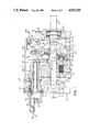
- FIG. 1 is a view in vertical cross-section through a variable displacement axial piston pump incorporating the present invention
- FIG. 2 is an enlarged view in section taken in the plane of the line 2--2 of FIG. 1;
- FIG. 3 is a fragmentary exploded view of cooperating portions of the shaft bushing and bore for the shaft bushing.
- FIG. 4 is an enlarged fragmentary view of the sleeve portion of the cylinder barrel.
- the invention is shown incorporated in a variable displacement axial piston pump.
- the pump has a cast housing 9 with a hollow interior to define a cavity 10.
- the housing 9 includes a crowned portion 11 which accommodates a control piston which will be described more fully hereafter.
- the open end of the housing 9 is closed by a valve plate 12 which is bolted to the housing.
- a draft shaft 13 is mounted in a roller bearing 14 supported in the housing at the shaft end of the pump.
- the inner end of the shaft 13 is journaled in a sleeve bearing or bushing 15 mounted in a bore 16 in the valve plate 12.
- the drive shaft 13 has splines 17 which engage with mating splines 18 on the interior of a cylinder barrel 19.
- the cylinder barrel 19 has a plurality of cylinder bores 20 each of which mounts a piston 21 whose end is formed as a ball 22. Piston shoes 23 are pressed about the balls 22 and operate against a flat face 24 of a movable swashblock 25. The series of piston shoes 23 are mounted in a shoe retainer plate 28 which has a spherical central opening that mates with a spherical fulcrum 29. The spherical fulcrum 29 is urged axially towards the swashblock 25 by a plurality of springs 30 mounted in the shaft end of the cylinder barrel 19.
- the effect of the springs 30 is to urge the spherical fulcrum 29 and the shoe retainer plate 28 axially towards the swashblock 25 to maintain the shoes 23 against the flat face 24 of the swashblock 25.
- the springs 30 also urge the valve face end of the cylinder barrel 19 against the valve plate 12 to operatively connect the bottoms of the cylinder bores 20 with inlet and outlet ports in the valve plate 12.
- the rear of the swashblock 25 has circular cylindrical bearing surfaces 31 that are seated in bearing liners 32 that are, in turn, held against curved bearing surfaces of a saddle 33.
- the opposite side of the saddle 33 is mounted in a counterbore 34 in an end wall of the housing 9 and the saddle 33 is restrained against radial or rotary movement by a pin 35.
- the cylinder barrel 19 has a projecting sleeve portion 37 that is journaled in a cylinder barrel bearing 38 which is mounted in the housing 9 and located between a shoulder 39 and a snap ring 40.
- the barrel bearing 38 is of known construction with a steel ring having its inner diameter coated with a low friction material such as polytetrafluoride.
- the position of the swashblock 25 in the saddle 33 can be varied to adjust the inclination of the face 24 of the swashblock from a position where it is perpendicular to the axis of the shaft 13 to a position where it is inclined to the shaft axis.
- the degree of inclination will determine the length of the strokes of the piston 21 as the cylinder barrel 19 is rotated by the shaft 13 and to thereby vary the volume of fluid pumped.
- the control for varying the position of the swashblock is mounted within the housing 9 in the crown 11.
- a control piston 45 is disposed in a sleeve 46 which in turn is sealed to a piston cap 47.
- One end of the control piston 45 is connected by a pin 48 to a link 49 which in turn is connected by a pin 50 to an arm 51 projecting from one side of the swashblock 25.
- a bias spring 54 is seated in the hollow interior of the control piston 45 and bears against an end wall of the piston cap 47. The spring 54 normally urges the control piston 45 to the right as viewed in FIG. 1 so that the swashblock 25 assumes a position of maximum stroke as illustrated in FIG. 1.
- the control piston 45 can be moved to the left as viewed in FIG. 1 to move the swashblock 25 towards a neutral position by introducing hydraulic fluid through an inlet 55 into a control pressure volume 56 where an enlarged diameter of the control piston 45 and an enlarged diameter in the sleeve 46 cooperate to cause the control piston 45 to move against the urgings of the spring 54.
- the spring 54 is assisted by the pressure of hydraulic fluid introduced through another inlet 57 into a pressure volume 58 which acts on the piston 45 by reason of a slightly reduced diameter of the piston 45.
- the space between the end of the piston 45 and the end of the piston cap 47 is connected to drain so that no pressure is built up in that space.
- the maximum and minimum stroke of the control piston 45 are set by adjustable stops.
- a stop pin 60 is manually located by a threaded stem 61 to have its end engage the corresponding end of the piston 45.
- a similar stop pin 62 can be positioned by a threaded stem 63 to have its end engage the side of a dowel pin 64 that extends laterally from the piston 45.
- our invention utilizes the centrifugal force imparted to fluid within the housing as the rotating group is rotated by the shaft, together with a unique form for the shaft bushing 15 and its bore 16 in the valve plate to insure proper distribution of lubricant over the surfaces of the bushing.
- the valve plate 12 has a pocket 70 into which the end of the shaft 13 projects. This pocket is closed by a cover plate 71.
- the pocket 70 functions as a reservoir for fluid to lubricate the bushing 15. Fluid is supplied to the reservoir 70 under a slight pressure head from the cavity 10 surrounding the cylinder barrel 19. As shown in FIG.
- the cavity 10 is connected to the reservoir 70 by means of an axial passageway 73 and a radial passageway 74 both formed in the valve plate 12.
- the cavity 10 is in turn connected by a radial passageway 75 in the cylinder barrel 19 to the space 76 between the inner diameter 77 of the cylinder barrel 19 and the outer diameter of the shaft 13.
- the bushing 15 is provided with a pair of elongated diametrically opposite slots 80 which extends along the axis of the bushing.
- the surface of the bushing bore 16 in the valve plate 12 is provided with diametrically opposed, axially extending recesses 82 and 83 which lead respectively from the reservoir 70 to the bushing slot 80 and from the bushing slot 80 to the space 76 between the cylinder barrel 19 and the shaft 13.
- Two slots 80 are required to accommodate both clockwise and counterclockwise shaft rotation, or for two direction operation. The reason is because the shaft 13 is deflected during operation by stroking forces so that there will be clearance between one side of the shaft and the bushing, and a slot 80 should always be located opposite the clearance.
- annular groove 90 is formed on the interior of the sleeve portion 37 of the cylinder barrel (see FIG. 4). The annular groove 90 accumulates fluid that leaks past the pistons 21.
- Fluid collected in the groove 90 will be moved radially by centrifugal force through a plurality of radial passageways 92 which lead through the sleeve portion 37 and to the outside diameter of the sleeve portion 37 and the mating interior diameter of the barrel bearing 38.
- the interior diameter of the barrel bearing 38 is provided with axial reliefs, in a known manner.
- variable displacement pump Although the invention has been described in relation to a variable displacement pump, it could as well be used with a variable displacement motor or with a fixed pump or motor.
Abstract
Description
Claims (5)
Priority Applications (6)
| Application Number | Priority Date | Filing Date | Title |
|---|---|---|---|
| US07/359,612 US4932310A (en) | 1989-06-01 | 1989-06-01 | Bearing lubrication in axial piston fluid devices |
| PCT/US1990/002932 WO1990015246A1 (en) | 1989-06-01 | 1990-05-31 | Bearing lubrication in axial piston fluid devices |
| JP2508290A JPH0794817B2 (en) | 1989-06-01 | 1990-05-31 | Axial piston fluid device |
| DE69019152T DE69019152T2 (en) | 1989-06-01 | 1990-05-31 | BEARING LUBRICATION IN AXIAL PISTON FLUID DEVICES. |
| CA002017964A CA2017964C (en) | 1989-06-01 | 1990-05-31 | Bearing lubrication in axial piston fluid devices |
| EP90908836A EP0474731B1 (en) | 1989-06-01 | 1990-05-31 | Bearing lubrication in axial piston fluid devices |
Applications Claiming Priority (1)
| Application Number | Priority Date | Filing Date | Title |
|---|---|---|---|
| US07/359,612 US4932310A (en) | 1989-06-01 | 1989-06-01 | Bearing lubrication in axial piston fluid devices |
Publications (1)
| Publication Number | Publication Date |
|---|---|
| US4932310A true US4932310A (en) | 1990-06-12 |
Family
ID=23414583
Family Applications (1)
| Application Number | Title | Priority Date | Filing Date |
|---|---|---|---|
| US07/359,612 Expired - Lifetime US4932310A (en) | 1989-06-01 | 1989-06-01 | Bearing lubrication in axial piston fluid devices |
Country Status (6)
| Country | Link |
|---|---|
| US (1) | US4932310A (en) |
| EP (1) | EP0474731B1 (en) |
| JP (1) | JPH0794817B2 (en) |
| CA (1) | CA2017964C (en) |
| DE (1) | DE69019152T2 (en) |
| WO (1) | WO1990015246A1 (en) |
Cited By (1)
| Publication number | Priority date | Publication date | Assignee | Title |
|---|---|---|---|---|
| CN109798232A (en) * | 2019-03-29 | 2019-05-24 | 潍柴动力股份有限公司 | Oblique tray type plunger pump motor |
Families Citing this family (3)
| Publication number | Priority date | Publication date | Assignee | Title |
|---|---|---|---|---|
| DE4423023C2 (en) * | 1994-06-30 | 1998-07-09 | Brueninghaus Hydromatik Gmbh | Axial piston machine with a cooling circuit for the cylinders and pistons |
| DE29503060U1 (en) * | 1995-02-23 | 1995-04-06 | Brueninghaus Hydromatik Gmbh | Axial piston machine |
| DE19924064B4 (en) * | 1999-05-26 | 2007-07-05 | Siemens Ag | displacement |
Citations (1)
| Publication number | Priority date | Publication date | Assignee | Title |
|---|---|---|---|---|
| US4167895A (en) * | 1978-06-26 | 1979-09-18 | The Oilgear Company | Axial pump with displacement control device |
Family Cites Families (5)
| Publication number | Priority date | Publication date | Assignee | Title |
|---|---|---|---|---|
| GB1200180A (en) * | 1966-12-14 | 1970-07-29 | Dowty Technical Dev Ltd | Swash plate pump |
| DE2101078A1 (en) * | 1971-01-12 | 1972-08-03 | Robert Bosch Gmbh, 7000 Stuttgart | Axial piston machine |
| US3779137A (en) * | 1971-09-27 | 1973-12-18 | Gen Motors Corp | Hydrostatic tilt box bearing |
| US3893375A (en) * | 1973-02-07 | 1975-07-08 | Caterpillar Tractor Co | Axial piston hydraulic device with forced lubrication means |
| US4710107A (en) * | 1986-04-15 | 1987-12-01 | The Oilgear Company | Swashblock lubrication in axial piston fluid displacement devices |
-
1989
- 1989-06-01 US US07/359,612 patent/US4932310A/en not_active Expired - Lifetime
-
1990
- 1990-05-31 WO PCT/US1990/002932 patent/WO1990015246A1/en active IP Right Grant
- 1990-05-31 EP EP90908836A patent/EP0474731B1/en not_active Expired - Lifetime
- 1990-05-31 JP JP2508290A patent/JPH0794817B2/en not_active Expired - Lifetime
- 1990-05-31 CA CA002017964A patent/CA2017964C/en not_active Expired - Lifetime
- 1990-05-31 DE DE69019152T patent/DE69019152T2/en not_active Expired - Lifetime
Patent Citations (1)
| Publication number | Priority date | Publication date | Assignee | Title |
|---|---|---|---|---|
| US4167895A (en) * | 1978-06-26 | 1979-09-18 | The Oilgear Company | Axial pump with displacement control device |
Cited By (1)
| Publication number | Priority date | Publication date | Assignee | Title |
|---|---|---|---|---|
| CN109798232A (en) * | 2019-03-29 | 2019-05-24 | 潍柴动力股份有限公司 | Oblique tray type plunger pump motor |
Also Published As
| Publication number | Publication date |
|---|---|
| JPH0794817B2 (en) | 1995-10-11 |
| JPH04503236A (en) | 1992-06-11 |
| DE69019152D1 (en) | 1995-06-08 |
| CA2017964C (en) | 2000-10-24 |
| CA2017964A1 (en) | 1990-12-01 |
| DE69019152T2 (en) | 1995-12-07 |
| EP0474731A1 (en) | 1992-03-18 |
| WO1990015246A1 (en) | 1990-12-13 |
| EP0474731B1 (en) | 1995-05-03 |
Similar Documents
| Publication | Publication Date | Title |
|---|---|---|
| US3319575A (en) | Piston | |
| US4637293A (en) | Slant plate type hydraulic device | |
| US3249061A (en) | Pump or motor device | |
| US2313407A (en) | Power transmission | |
| KR20090014332A (en) | Axial piston machine with hydrostatic support of the holding-down device | |
| US3450058A (en) | Segmented oil film bearing for fluid translator | |
| US1925378A (en) | Pump | |
| JPH01250661A (en) | Hydraulic speed change gear | |
| GB2163493A (en) | Radial piston device | |
| US2862455A (en) | Hydrodynamic machine | |
| US4932310A (en) | Bearing lubrication in axial piston fluid devices | |
| US2972961A (en) | Hydrostatic lubricating apparatus | |
| US2164888A (en) | Variable delivery pump | |
| US3289604A (en) | Fluid device | |
| US11215172B2 (en) | Hydrostatic positive displacement machine | |
| CN209855979U (en) | Axial plunger pump or motor | |
| US2483856A (en) | Hydraulic mechanism | |
| US3006284A (en) | Swash-plate pump | |
| US3793923A (en) | Radial piston hydraulic machines | |
| US2111657A (en) | Hydraulic pump or motor | |
| US3453965A (en) | Valve plate motor pump | |
| GB2055984A (en) | Dual piston pump | |
| US3980003A (en) | Variable hydrostatic bearing between barrel and head of axial piston units | |
| JPH0626447A (en) | Hydraulic pump motor | |
| US3800672A (en) | Clearance adjusting arrangement for an axial piston machine |
Legal Events
| Date | Code | Title | Description |
|---|---|---|---|
| AS | Assignment |
Owner name: OILGEAR COMPANY, THE, MILWAUKEE, WI A CORP. OF WI Free format text: ASSIGNMENT OF ASSIGNORS INTEREST.;ASSIGNORS:JENDRZEJEK, GARY S.;VOIGT, MICHAEL J.;REEL/FRAME:005087/0119 Effective date: 19890601 |
|
| STCF | Information on status: patent grant |
Free format text: PATENTED CASE |
|
| FEPP | Fee payment procedure |
Free format text: PAYOR NUMBER ASSIGNED (ORIGINAL EVENT CODE: ASPN); ENTITY STATUS OF PATENT OWNER: LARGE ENTITY |
|
| FPAY | Fee payment |
Year of fee payment: 4 |
|
| FPAY | Fee payment |
Year of fee payment: 8 |
|
| FEPP | Fee payment procedure |
Free format text: PAYER NUMBER DE-ASSIGNED (ORIGINAL EVENT CODE: RMPN); ENTITY STATUS OF PATENT OWNER: LARGE ENTITY Free format text: PAYOR NUMBER ASSIGNED (ORIGINAL EVENT CODE: ASPN); ENTITY STATUS OF PATENT OWNER: LARGE ENTITY |
|
| FPAY | Fee payment |
Year of fee payment: 12 |
|
| AS | Assignment |
Owner name: M&I MARSHALL & IISLEY BANK, WISCONSIN Free format text: SECURITY INTEREST;ASSIGNOR:OILGEAR COMPANY, THE;REEL/FRAME:014066/0132 Effective date: 20030211 |
|
| AS | Assignment |
Owner name: THE OILGEAR COMPANY, WISCONSIN Free format text: PATENT RELEASE;ASSIGNOR:M&I MARSHALL & ILSLEY BANK;REEL/FRAME:015667/0619 Effective date: 20050128 Owner name: LASALLE BUSINESS CREDIT, LLC, AS AGENT, ILLINOIS Free format text: SECURITY AGREEMENT;ASSIGNOR:THE OILGEAR COMPANY;REEL/FRAME:015667/0623 Effective date: 20050128 |
|
| AS | Assignment |
Owner name: THE OILGEAR COMPANY, WISCONSIN Free format text: RELEASE OF PATENT SECURITY AGREEMENT;ASSIGNOR:LASALLE BUSINESS CREDIT, LLC;REEL/FRAME:018654/0717 Effective date: 20061218 Owner name: JPMORGAN CHASE BANK, N.A., WISCONSIN Free format text: COLLATERAL ASSIGNMENT OF PATENTS AS SECURITY;ASSIGNOR:THE OILGEAR COMPANY;REEL/FRAME:018654/0878 Effective date: 20061215 |
|
| AS | Assignment |
Owner name: JPMORGAN CHASE BANK, N.A., WISCONSIN Free format text: CORRECTIVE ASSIGNMENT TO CORRECT THE THE INCORRECTLY LISTED PATENT APPLICATION NUMBER, LISTED ORIGINALLY AS A REGISTERED PATENT, PREVIOUSLY RECORDED ON REEL 018654 FRAME 0878;ASSIGNOR:THE OILGEAR COMPANY;REEL/FRAME:018720/0045 Effective date: 20061215 |
|
| AS | Assignment |
Owner name: THE OILGEAR COMPANY, MICHIGAN Free format text: TERMINATION OF ASSIGNMENT;ASSIGNOR:JPMORGAN CHASE BANK, N.A.;REEL/FRAME:045789/0333 Effective date: 20180327 |