US4923393A - Fuel fired burner - Google Patents
Fuel fired burner Download PDFInfo
- Publication number
- US4923393A US4923393A US06/883,502 US88350286A US4923393A US 4923393 A US4923393 A US 4923393A US 88350286 A US88350286 A US 88350286A US 4923393 A US4923393 A US 4923393A
- Authority
- US
- United States
- Prior art keywords
- burner
- wall
- chamber
- slots
- gas
- Prior art date
- Legal status (The legal status is an assumption and is not a legal conclusion. Google has not performed a legal analysis and makes no representation as to the accuracy of the status listed.)
- Expired - Fee Related
Links
Images


Classifications
-
- F—MECHANICAL ENGINEERING; LIGHTING; HEATING; WEAPONS; BLASTING
- F24—HEATING; RANGES; VENTILATING
- F24H—FLUID HEATERS, e.g. WATER OR AIR HEATERS, HAVING HEAT-GENERATING MEANS, e.g. HEAT PUMPS, IN GENERAL
- F24H1/00—Water heaters, e.g. boilers, continuous-flow heaters or water-storage heaters
- F24H1/22—Water heaters other than continuous-flow or water-storage heaters, e.g. water heaters for central heating
- F24H1/24—Water heaters other than continuous-flow or water-storage heaters, e.g. water heaters for central heating with water mantle surrounding the combustion chamber or chambers
- F24H1/26—Water heaters other than continuous-flow or water-storage heaters, e.g. water heaters for central heating with water mantle surrounding the combustion chamber or chambers the water mantle forming an integral body
-
- F—MECHANICAL ENGINEERING; LIGHTING; HEATING; WEAPONS; BLASTING
- F23—COMBUSTION APPARATUS; COMBUSTION PROCESSES
- F23C—METHODS OR APPARATUS FOR COMBUSTION USING FLUID FUEL OR SOLID FUEL SUSPENDED IN A CARRIER GAS OR AIR
- F23C5/00—Disposition of burners with respect to the combustion chamber or to one another; Mounting of burners in combustion apparatus
-
- F—MECHANICAL ENGINEERING; LIGHTING; HEATING; WEAPONS; BLASTING
- F23—COMBUSTION APPARATUS; COMBUSTION PROCESSES
- F23D—BURNERS
- F23D14/00—Burners for combustion of a gas, e.g. of a gas stored under pressure as a liquid
- F23D14/30—Inverted burners, e.g. for illumination
-
- F—MECHANICAL ENGINEERING; LIGHTING; HEATING; WEAPONS; BLASTING
- F23—COMBUSTION APPARATUS; COMBUSTION PROCESSES
- F23D—BURNERS
- F23D14/00—Burners for combustion of a gas, e.g. of a gas stored under pressure as a liquid
- F23D14/46—Details, e.g. noise reduction means
- F23D14/48—Nozzles
- F23D14/58—Nozzles characterised by the shape or arrangement of the outlet or outlets from the nozzle, e.g. of annular configuration
- F23D14/583—Nozzles characterised by the shape or arrangement of the outlet or outlets from the nozzle, e.g. of annular configuration of elongated shape, e.g. slits
-
- F—MECHANICAL ENGINEERING; LIGHTING; HEATING; WEAPONS; BLASTING
- F24—HEATING; RANGES; VENTILATING
- F24H—FLUID HEATERS, e.g. WATER OR AIR HEATERS, HAVING HEAT-GENERATING MEANS, e.g. HEAT PUMPS, IN GENERAL
- F24H8/00—Fluid heaters characterised by means for extracting latent heat from flue gases by means of condensation
-
- Y—GENERAL TAGGING OF NEW TECHNOLOGICAL DEVELOPMENTS; GENERAL TAGGING OF CROSS-SECTIONAL TECHNOLOGIES SPANNING OVER SEVERAL SECTIONS OF THE IPC; TECHNICAL SUBJECTS COVERED BY FORMER USPC CROSS-REFERENCE ART COLLECTIONS [XRACs] AND DIGESTS
- Y02—TECHNOLOGIES OR APPLICATIONS FOR MITIGATION OR ADAPTATION AGAINST CLIMATE CHANGE
- Y02B—CLIMATE CHANGE MITIGATION TECHNOLOGIES RELATED TO BUILDINGS, e.g. HOUSING, HOUSE APPLIANCES OR RELATED END-USER APPLICATIONS
- Y02B30/00—Energy efficient heating, ventilation or air conditioning [HVAC]
Definitions
- the present invention relates to a fuel fired burner, and particularly a gas fired burner, which preferably is of the fully premixed type ie. one in which the gas is mixed with all the combustion air in the mixing chamber before the gas is combusted.
- Fully premixed burners have certain advantages over partially aerated type burners (ie. burners of the type in which only some of the combustion air is mixed with the gas before the gas is admitted to the combustion chamber.)
- fully premixed burners can be arranged to fire the flame downwardly whereas partially aerated burners are generally unsuitable for such operation.
- Both fully premixed and partially aerated burners can be operated over a range of gas flow rates ie. burner heat outputs. This range is defined as the turndown ratio which comprises the ratio of the maximum/minimum flow rates available for combustion. This ability is a great advantage in certain type of applications, for example, where the burner is to be used in a central heating boiler in order to maximise efficiency and to increase reliability of operation.
- this ratio lies between 10 and 15:1 but in the types of fully premixed burner currently available for small gas appliances it is limited to no more than 2:1. This is because when the current types of premixed burner are operated at ratios of greater than 2:1 certain undesirable effects begin to appear.
- the phenomenon of "flame lift” begins to occur.
- the flame partially or completely detaches itself from the burner outlet ports and becomes very unstable, giving rise to poor combustion and/or burner shut down by the safety device which monitors the flame.
- the surfaces surrounding the ports may overheat and can become damaged, or can cause the flame to propagate back through the ports into the burner with disastrous results.
- a fuel fired burner comprising a plenum chamber formed by walls, one of which has an inlet to receive fuel and another of which is formed with at least one slot communicating with the chamber and serving as an outlet for the fuel.
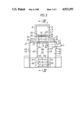
- FIG. 1 is a view of the burner shown partly broken away for clarity
- FIG. 2 is view looking on the lower face, from below, of the burner shown in FIG. 1,
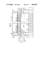
- FIG. 3 is a transverse section through the burner shown mounted on a heat exchanger of a gas fired boiler
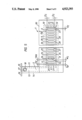
- FIG. 4 is a view along the lines IV--IV of FIG. 3.
- FIG. 5 corresponds to FIG. 2 but shows a variant of the slot shape.
- the burner 1 shown in a downfiring mode in FIGS. 1, 3 and 4 comprises an elongated plenum chamber 2 having adjoining one end a mixing chamber 3 for supplying a mixture of fuel gas and air to the plenum chamber 2 by way of an inlet 4, one wall of the chamber 2 comprising a plate 5 provided with several slots 6 serving as outlets for the gas/air mixture for subsequent ignition at a point outside the plenum chamber 2.
- the chamber 2 is also formed by an uppermost horizontal wall 7, two vertical side walls 8,9, a vertical end wall 10 and opposite the wall 10 a further vertical end wall 11 which forms a common part of the mixing chamber 3 and includes the inlet 4 by means of which the plenum chamber 2 and the mixing chamber 3 communicate.
- the mixing chamber 3 is formed by an uppermost horizontal wall 12 which adjoins the uppermost wall 7 of the plenum chamber 2, a lowermost horizontal wall 13, a vertical side wall 14, a vertical side wall 11 (including a part common to the plenum chamber 2) and an end wall forming part of the wall 8 of the plenum chamber 2.
- the mixing chamber 3 lies adjacent to one end of the plenum chamber 2 and extends at right angles away therefrom.
- the far end 15 of the mixing chamber 3 (see FIGS. 1 and 2) is open and is surrounded by a flange 16 for connecting the chamber 3 to a suitable source of pressurised air.
- the lowermost wall 13 of the chamber 3 is provided with an inlet opening 17 and a stub pipe 18 by means of which the mixing chamber 3 can be connected to a suitable source of fuel gas.
- the plate 5 is generally rectangular in shape as will be clear from FIG. 2 and is formed with an upstanding rectangular rim 19 (shown in outline in FIG. 2) having two side walls 20 and two end walls 21, upon which rim 19 is seated a further rectangular plate 22 (shown most clearly in FIGS. 3 and 4) for purposes to be described.
- the plate 5 is also provided with a depending rectangular rim 23 disposed generally opposite to the rim 19, the rim 23 having two side walls 24 and two end walls 25.
- This rim 23 serves as a flame stabiliser as will be further described subsequently.
- the slots 6 are generally rectangular in shape preferably oblong as shown but they could be square-shaped and are formed by two longer walls 27 extending parallel to the end walls of the rims 21 and 23 and two shorter walls 28 extending generally parallel to the side walls of the rims 21 and 23 as shown most clearly in FIG. 2. As shown in FIG. 5, the shorter walls 28 may advantageously be concavely curved. This arrangement reduces the incidence of hot-spots occurring at corners which are absent in this arrangement.
- the slots 6 serve as outlets for the fuel gas/air mixture leaving the plenum chamber 2.
- a further rectangular plate 22 (FIGS. 1, 3 and 4). This is provided with a multiplicity of through-going apertures 29 which may be circular.
- the plate 22 serves to distribute the fuel gas/air mixture to the slotted plate 5.
- fuel gas is supplied to the mixing chamber 3 by way of the inlet 17 and air is supplied by way of the inlet 15.
- the mixture After mixing in the chamber 3 the mixture enters the plenum chamber 2 by way of the inlet 4 and emerges from the burner 1 by way of the plates 22 and 5.
- Ignition of the gas/air mixture takes place after the mixture has emerged from the slots 6 in the plate 5. Such ignition may be effected by ignition electrodes.
- the burner 1 is suitable for use in a gas-fired boiler particularly a boiler of the condensing type.
- the burner 1 may be mounted to fire downwardly into the heat exchanger as shown in FIGS. 3 and 4.
- the heat exchanger 40 which may be of aluminium, comprises a central open ended duct 41 extending vertically, into which duct 41 the burner 1 fires in a downward direction and an outer surrounding chamber 42 through which water circulates in an upward direction.
- the central duct 41 is rectangular in section and comprises two elongated vertical side walls 43, and two vertical end walls 44 extending at right angles to the side walls 43.
- the outer chamber 42 is formed by the space enclosed between the inner walls 43 and 44 (also common to the central duct 41) and two outer elongated vertical side walls 45, two outer vertical end walls 46, a horizontal top wall 47 connecting the inner and outer walls and a horizontal bottom wall (not shown).
- the burner 1 is mounted over the opening at the upper end of the central duct 44, with the plate flange 30 engaging the top wall 47 of the heat exchanger 40 by way of a gasket (not shown).
- the burner plate 5 is dimensioned so that its depending rim 23 fits within the opening adjacent to the inner walls of the heat exchanger 40.
- a pair of spark ignition electrodes 48 (only one shown) to provide sparks serving to ignite fuel gas leaving the burner outlet slots 6.
- a further electrode (not shown) extending through one pair of the side walls 43 and 45 of the heat exchanger 40 is positioned to detect the presence or absence of a flame from the burner 1.
- the fin elements 49 and 50 are arranged in horizontal and vertical rows and as shown in FIG. 4.
- the fins are arranged so that the horizontal rows on opposite walls lie in the same plane but the vertical rows lie in offset planes.
Landscapes
- Engineering & Computer Science (AREA)
- Chemical & Material Sciences (AREA)
- Combustion & Propulsion (AREA)
- Mechanical Engineering (AREA)
- General Engineering & Computer Science (AREA)
- Physics & Mathematics (AREA)
- Thermal Sciences (AREA)
- Gas Burners (AREA)
Abstract
Description
Claims (8)
Ls≧Ws
Ls≧2×Ws.
Priority Applications (1)
| Application Number | Priority Date | Filing Date | Title |
|---|---|---|---|
| US07/475,275 US5059115A (en) | 1985-06-13 | 1990-02-05 | Fuel fired burner |
Applications Claiming Priority (1)
| Application Number | Priority Date | Filing Date | Title |
|---|---|---|---|
| GB08514986A GB2176588B (en) | 1985-06-13 | 1985-06-13 | Fuel fired burner |
Related Child Applications (1)
| Application Number | Title | Priority Date | Filing Date |
|---|---|---|---|
| US07/475,275 Continuation US5059115A (en) | 1985-06-13 | 1990-02-05 | Fuel fired burner |
Publications (1)
| Publication Number | Publication Date |
|---|---|
| US4923393A true US4923393A (en) | 1990-05-08 |
Family
ID=10580695
Family Applications (1)
| Application Number | Title | Priority Date | Filing Date |
|---|---|---|---|
| US06/883,502 Expired - Fee Related US4923393A (en) | 1985-06-13 | 1986-07-08 | Fuel fired burner |
Country Status (2)
| Country | Link |
|---|---|
| US (1) | US4923393A (en) |
| GB (1) | GB2176588B (en) |
Cited By (2)
| Publication number | Priority date | Publication date | Assignee | Title |
|---|---|---|---|---|
| GB2323431A (en) * | 1997-03-18 | 1998-09-23 | Lin Arlo Hwai Tay | Control mechanism for a gas fuelled soldering iron |
| CN101191615B (en) * | 2006-11-30 | 2011-03-30 | 林内株式会社 | All primary combustion burner |
Families Citing this family (8)
| Publication number | Priority date | Publication date | Assignee | Title |
|---|---|---|---|---|
| DE3868815D1 (en) * | 1987-09-26 | 1992-04-09 | Ruhrgas Ag | GAS BURNER. |
| CN1017744B (en) * | 1988-12-26 | 1992-08-05 | 株式会社日立制作所 | Boiler for low nitrogen oxide |
| GB2231949A (en) * | 1989-05-26 | 1990-11-28 | Burco Dean Appliances Ltd | Gas burner |
| GB2269892B (en) * | 1992-08-18 | 1995-09-06 | British Gas Plc | Fuel fired burners |
| GB2272508B (en) * | 1992-11-12 | 1995-10-18 | British Gas Plc | Fuel fired burners |
| EP0698766B1 (en) * | 1994-08-26 | 1998-07-22 | Caradon Ideal Limited | Gas burner |
| GB2302401B (en) | 1995-06-15 | 1999-08-04 | British Gas Plc | Fuel fired burners |
| GB2316479B (en) * | 1996-08-14 | 1999-12-15 | Aeromatic Co Ltd | Improvements in or relating to gas burners |
Citations (16)
| Publication number | Priority date | Publication date | Assignee | Title |
|---|---|---|---|---|
| US1830393A (en) * | 1928-05-16 | 1931-11-03 | Bernard A Geurink | Gas burner |
| DE627024C (en) * | 1933-01-03 | 1936-03-06 | Kueppersbusch & Soehne Akt Ges | Heating, cooking and melting burners operated with compressed gas mixtures |
| GB541317A (en) * | 1940-09-12 | 1941-11-21 | Shorter Process Company Ltd | Improvements in or relating to blowpipe apparatus |
| US3131752A (en) * | 1962-07-19 | 1964-05-05 | Lincoln Brass Works | Gas burner structure |
| GB1103073A (en) * | 1964-03-07 | 1968-02-14 | Konink Fabrieken Diepenbrock & | Gas burner |
| GB1135140A (en) * | 1966-11-17 | 1968-11-27 | Duiker App Nfabriek N V | Tubular gas burner |
| DE1626001A1 (en) * | 1964-01-17 | 1969-09-04 | Duiker App Nfabriek N V | Burners for gaseous fuels |
| AU3802268A (en) * | 1969-05-20 | 1970-12-03 | Radiation (Australia) Proprietary Limited | Conversion apparatus |
| GB1224443A (en) * | 1968-07-10 | 1971-03-10 | Vaillant Joh Kg | Bunsen burner for gas-fired heating apparatus |
| GB1265759A (en) * | 1969-06-12 | 1972-03-08 | ||
| EP0009831A2 (en) * | 1978-07-28 | 1980-04-16 | Aldo Polidoro | Atmospheric gas burner with groups of vents for the passage of the mixture of combustible gas and combustion air |
| GB1579829A (en) * | 1977-07-29 | 1980-11-26 | Bray & Co Ltd Geo | Gas burners |
| FR2481415A1 (en) * | 1980-04-23 | 1981-10-30 | Fulpin Jacques | Burner for pressurised gas - has powered air induction and divergent passage for delivery of mixture |
| GB2076956A (en) * | 1980-05-29 | 1981-12-09 | Matsushita Electric Ind Co Ltd | Burner |
| EP0085470A2 (en) * | 1982-02-02 | 1983-08-10 | Beondu A.G. | A condensing boiler |
| EP0130742A2 (en) * | 1983-06-23 | 1985-01-09 | Matsushita Electric Industrial Co., Ltd. | High load gas combustion apparatus |
-
1985
- 1985-06-13 GB GB08514986A patent/GB2176588B/en not_active Expired
-
1986
- 1986-07-08 US US06/883,502 patent/US4923393A/en not_active Expired - Fee Related
Patent Citations (16)
| Publication number | Priority date | Publication date | Assignee | Title |
|---|---|---|---|---|
| US1830393A (en) * | 1928-05-16 | 1931-11-03 | Bernard A Geurink | Gas burner |
| DE627024C (en) * | 1933-01-03 | 1936-03-06 | Kueppersbusch & Soehne Akt Ges | Heating, cooking and melting burners operated with compressed gas mixtures |
| GB541317A (en) * | 1940-09-12 | 1941-11-21 | Shorter Process Company Ltd | Improvements in or relating to blowpipe apparatus |
| US3131752A (en) * | 1962-07-19 | 1964-05-05 | Lincoln Brass Works | Gas burner structure |
| DE1626001A1 (en) * | 1964-01-17 | 1969-09-04 | Duiker App Nfabriek N V | Burners for gaseous fuels |
| GB1103073A (en) * | 1964-03-07 | 1968-02-14 | Konink Fabrieken Diepenbrock & | Gas burner |
| GB1135140A (en) * | 1966-11-17 | 1968-11-27 | Duiker App Nfabriek N V | Tubular gas burner |
| GB1224443A (en) * | 1968-07-10 | 1971-03-10 | Vaillant Joh Kg | Bunsen burner for gas-fired heating apparatus |
| AU3802268A (en) * | 1969-05-20 | 1970-12-03 | Radiation (Australia) Proprietary Limited | Conversion apparatus |
| GB1265759A (en) * | 1969-06-12 | 1972-03-08 | ||
| GB1579829A (en) * | 1977-07-29 | 1980-11-26 | Bray & Co Ltd Geo | Gas burners |
| EP0009831A2 (en) * | 1978-07-28 | 1980-04-16 | Aldo Polidoro | Atmospheric gas burner with groups of vents for the passage of the mixture of combustible gas and combustion air |
| FR2481415A1 (en) * | 1980-04-23 | 1981-10-30 | Fulpin Jacques | Burner for pressurised gas - has powered air induction and divergent passage for delivery of mixture |
| GB2076956A (en) * | 1980-05-29 | 1981-12-09 | Matsushita Electric Ind Co Ltd | Burner |
| EP0085470A2 (en) * | 1982-02-02 | 1983-08-10 | Beondu A.G. | A condensing boiler |
| EP0130742A2 (en) * | 1983-06-23 | 1985-01-09 | Matsushita Electric Industrial Co., Ltd. | High load gas combustion apparatus |
Cited By (3)
| Publication number | Priority date | Publication date | Assignee | Title |
|---|---|---|---|---|
| GB2323431A (en) * | 1997-03-18 | 1998-09-23 | Lin Arlo Hwai Tay | Control mechanism for a gas fuelled soldering iron |
| GB2323431B (en) * | 1997-03-18 | 2000-11-08 | Lin Arlo Hwai Tay | Gas welding guns |
| CN101191615B (en) * | 2006-11-30 | 2011-03-30 | 林内株式会社 | All primary combustion burner |
Also Published As
| Publication number | Publication date |
|---|---|
| GB2176588A (en) | 1986-12-31 |
| GB2176588B (en) | 1989-02-08 |
| GB8514986D0 (en) | 1985-07-17 |
Similar Documents
| Publication | Publication Date | Title |
|---|---|---|
| US4541410A (en) | Apparatus and method for burning a combustible gas, and a heat exchanger for use in this apparatus | |
| US5775268A (en) | High efficiency vertical tube water heater apparatus | |
| CA2629127C (en) | Inwardly firing burner and uses thereof | |
| US4923393A (en) | Fuel fired burner | |
| KR102365634B1 (en) | Metal fiber burner for boiler | |
| KR102332112B1 (en) | Boiler heat exchanger with insulation | |
| US3509867A (en) | Radiant and convective heater | |
| EP0381252B1 (en) | Fuel fired burner | |
| US5322050A (en) | High efficiency fuel-fired condensing furnace having a compact heat exchanger system | |
| US5611330A (en) | Induced draft fryer | |
| US3908603A (en) | Boiler and elements therefor | |
| US5724887A (en) | Frying device | |
| US6000392A (en) | Steamer gas oven | |
| US5059115A (en) | Fuel fired burner | |
| US3734065A (en) | Fluid heater | |
| CA2469438C (en) | Finned tube water heater | |
| KR20210133453A (en) | Boiler heat exchanger | |
| US4123995A (en) | Hot water or steam boiler | |
| GB2123944A (en) | Heating air in fuel-effect gas fires | |
| EP0205993A3 (en) | A solid fuel fired inverted flame boiler for central heating systems and for hot water systems generally | |
| CN216953059U (en) | Wall-mounted furnace and combustion device | |
| SU1089362A1 (en) | Hot-water boiler | |
| KR900008083Y1 (en) | Boiler with multiple combustion chamber | |
| KR820000558Y1 (en) | Hot water boiler | |
| RU1796048C (en) | Hot-water boiler |
Legal Events
| Date | Code | Title | Description |
|---|---|---|---|
| AS | Assignment |
Owner name: BRITISH GAS PLC, RIVERMILL HOUSE 152 GROSVENOR ROA Free format text: ASSIGNMENT OF ASSIGNORS INTEREST.;ASSIGNOR:BRITISH GAS CORPORATION;REEL/FRAME:004859/0891 Effective date: 19870512 Owner name: BRITISH GAS PLC, ENGLAND Free format text: ASSIGNMENT OF ASSIGNORS INTEREST;ASSIGNOR:BRITISH GAS CORPORATION;REEL/FRAME:004859/0891 Effective date: 19870512 |
|
| AS | Assignment |
Owner name: BRITISH GAS CORPORATION, ENGLAND Free format text: ASSIGNMENT OF ASSIGNORS INTEREST.;ASSIGNOR:SUTTON, DAVID M.;REEL/FRAME:005230/0751 Effective date: 19860627 |
|
| FEPP | Fee payment procedure |
Free format text: PAYOR NUMBER ASSIGNED (ORIGINAL EVENT CODE: ASPN); ENTITY STATUS OF PATENT OWNER: LARGE ENTITY |
|
| FPAY | Fee payment |
Year of fee payment: 4 |
|
| FPAY | Fee payment |
Year of fee payment: 8 |
|
| REMI | Maintenance fee reminder mailed | ||
| LAPS | Lapse for failure to pay maintenance fees | ||
| STCH | Information on status: patent discontinuation |
Free format text: PATENT EXPIRED DUE TO NONPAYMENT OF MAINTENANCE FEES UNDER 37 CFR 1.362 |
|
| FP | Lapsed due to failure to pay maintenance fee |
Effective date: 20020508 |