TECHNICAL FIELD
This invention relates to a power thermo-coupling unit and particularly to a support for mounting such a unit.
PRIOR ART STATEMENT
It is a common practice to elastically support a power thermo-coupling unit such as an internal combustion engine generator set or other engine driven machine on a frame or unit support. The unit support is secured to a floor of the building and contains all of the exhaust gas heat exchangers or radiators necessary for a power thermo-coupling unit, as well as mufflers, for the engine exhaust. The unit support includes a rectangular-shaped frame which has openings in all its vertical sides. In order to increase overall stability, the unit support has a central column which divides the unit support into two parts. Two longitudinal holes are arranged in the central column through which components of mufflers and heat exchangers are guided and installed in the unit support. For the purpose of maintaining, cleaning and replacing these components, they are removed by pulling them in a longitudinal direction through openings in the front wall of the unit support.
A disadvantage of this arrangement lies in the fact that, in order to remove the mufflers and the exhaust gas heat exchangers longitudinally through the openings in the front wall, floor space must be made available to accommodate the length of the muffler and/or the exhaust gas heat exchanger and the muffler and/or exhaust gas heat exchanger must have a high level of rigidity because of the length thereof.
OBJECTS AND BRIEF DESCRIPTION OF THE INVENTION
It is a main object of this invention to provide a power thermo-coupling unit which is cost efficient and in which the muffler and exhaust gas heat exchanger components can be easily removed for cleaning or replacement.
This invention meets the foregoing object by providing a muffler and an exhaust gas heat exchanger, each designed to have at least two separate components with the length of each component being less than the distance between the central column and the front or rear side. This permits the components to be disconnected and shifted laterally through side openings. Thus, the muffler and the exhaust gas heat exchanger are readily accessible for maintenance and replacement. Because of their limited length, the components are sufficiently light in weight to permit a serviceman to pull them laterally from the unit support. It is not necessary to have maneuvering space available at the front end of the unit support, and only a small amount of space is required at the longitudinal side of the unit support to permit removal of the muffler and heat exchanger components. In addition, a division of the muffler and heat exchanger into separate components permits removal of only that component which needs to be removed for maintenance or repair. The individual components can also be manufactured from various materials chosen to meet the operational requirements of the components.
The height of the components is less than the vertical dimension of the side openings of the unit support to permit the components to be removed through such side openings.
In the preferred embodiment of the invention the muffler includes two components, one of which forms a reflection chamber and the other of which forms an absorption chamber. In a similar manner, the exhaust gas heat exchanger includes two components, one of which is designed as a high-temperature component and the other of which is designed as a low-temperature component.
In the case of the exhaust gas heat exchanger, the division into two components permits inexpensive steel to be used for the high-temperature component and more expensive alloy steel to be used in the low-temperature component where condensate occurs. This results in a significant savings. The separate replaceability of the components is a particular advantage because the service life of the components will be different.
It is desirable to connect the reflection chamber component with the absorption chamber component and the low-temperature component with the high-temperature component by means of connecting pieces which extend through longitudinal openings in the central column. The connecting pieces are preferably designed for flanged connection to the components.
In the preferred embodiment of the invention, the components are provided with support brackets which are guided in tracks on the unit support to facilitate lateral sliding removal of the components.
BRIEF DESCRIPTION OF THE DRAWINGS
Additional features of the invention can be found in the following description of the drawings illustrating one embodiment of the invention, in which:
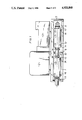
FIG. 1 is a side view of a power thermo-coupling unit; and
FIG. 2 is a section view on a horizontal plane in which the muffler and heat exchanger components lie.
DETAILED DESCRIPTION OF THE INVENTION
FIG. 1 is a side view of a power thermo-coupling unit incorporating the present invention. An engine and generator set, consisting of an engine 2 drivingly connected to a generator 3, is elastically supported on a unit pad or support 1. Working machines other than an engine and generator unit may also be thus supported. The unit support 1 consists of a rectangular frame having top, bottom and end walls defining openings 11 on both its lateral sides. In order to increase stability of the unit support 1, a central column 8 extends laterally and vertically between the top and bottom walls and divides the interior of the unit support into two adjacent compartments. In these compartments of the unit support 1, a muffler 4, 5 and an exhaust gas heat exchanger 6, 7 (see FIG. 2) are supported and positioned parallel to the longitudinal vertical plane of the generator set and to the longitudinal sides of the support unit 1.
The muffler 4, 5 and.. the exhaust gas heat exchanger 6, 7 each consist of two separable components connected to each other by connecting pieces 10 having flanged connections with the related components. The connecting pieces 10 extend through longitudinal openings in the central column 8 and consist of a pipe with radially outwardly extending flanges at each end which are secured to flanges on the separable components by suitable releasable fastening means shown at 13:
FIG. 2 illustrates removability of the components, which is an important feature of the invention. The two components of the muffler 4, 5 consist of a reflection chamber 4 and an absorption chamber 5, with the absorption chamber 5 series connected in downstream relation to the reflection chamber 4. The direction of flow is indicated by arrows in FIG. 2. The exhaust gas heat exchanger components 6, 7 are series connected downstream of the muffler 4, 5 and are disposed parallel to the muffler 4, 5. A U-shaped connector changes the direction of the flow from the muffler 4, 5 one hundred and eighty degrees so that the exhaust gases flow through the heat exchanger 6, 7 in an opposite parallel direction to its flow through the muffler 4, 5. In the exhaust gas heat exchanger 6, 7, the low-temperature component 6 is arranged downstream in the direction of flow from the high-temperature component 7.
Support brackets 12 are provided on the components by which the components are secured to the unit support by releasable fasteners, not shown. In order to facilitate easy sliding removal of the components from the unit support 1, the brackets 12 are guided by tracks shown at 14. Thus the components with their brackets 12 may be slid like a shelf or drawer from the unit support 1.
This invention provides a power thermo-coupling unit which is compact, easy to maintain and cost effective.