US4901636A - Spindle press - Google Patents
Spindle press Download PDFInfo
- Publication number
- US4901636A US4901636A US07/252,271 US25227188A US4901636A US 4901636 A US4901636 A US 4901636A US 25227188 A US25227188 A US 25227188A US 4901636 A US4901636 A US 4901636A
- Authority
- US
- United States
- Prior art keywords
- spindle
- front wall
- press
- feed side
- screen casing
- Prior art date
- Legal status (The legal status is an assumption and is not a legal conclusion. Google has not performed a legal analysis and makes no representation as to the accuracy of the status listed.)
- Expired - Fee Related
Links
- 239000012530 fluid Substances 0.000 claims abstract description 28
- 239000007921 spray Substances 0.000 claims abstract description 9
- 239000000463 material Substances 0.000 claims description 27
- 238000007789 sealing Methods 0.000 claims description 15
- 238000009833 condensation Methods 0.000 claims description 5
- 230000005494 condensation Effects 0.000 claims description 5
- 238000003825 pressing Methods 0.000 claims description 5
- 241000219310 Beta vulgaris subsp. vulgaris Species 0.000 claims description 4
- 235000021536 Sugar beet Nutrition 0.000 claims description 4
- 208000002474 Tinea Diseases 0.000 claims 1
- 241000893966 Trichophyton verrucosum Species 0.000 claims 1
- 238000010276 construction Methods 0.000 description 8
- 239000004809 Teflon Substances 0.000 description 6
- 229920006362 Teflon® Polymers 0.000 description 6
- 239000004033 plastic Substances 0.000 description 6
- 229920003023 plastic Polymers 0.000 description 6
- 230000007423 decrease Effects 0.000 description 3
- 239000002184 metal Substances 0.000 description 3
- 229910001220 stainless steel Inorganic materials 0.000 description 3
- 239000010935 stainless steel Substances 0.000 description 3
- 239000000126 substance Substances 0.000 description 3
- 230000006835 compression Effects 0.000 description 2
- 238000007906 compression Methods 0.000 description 2
- 230000002349 favourable effect Effects 0.000 description 2
- 230000000149 penetrating effect Effects 0.000 description 2
- 238000003466 welding Methods 0.000 description 2
- 238000004458 analytical method Methods 0.000 description 1
- 230000004323 axial length Effects 0.000 description 1
- 230000008878 coupling Effects 0.000 description 1
- 238000010168 coupling process Methods 0.000 description 1
- 238000005859 coupling reaction Methods 0.000 description 1
- 238000007599 discharging Methods 0.000 description 1
- 238000005516 engineering process Methods 0.000 description 1
- 210000004907 gland Anatomy 0.000 description 1
- 238000004519 manufacturing process Methods 0.000 description 1
- 238000000034 method Methods 0.000 description 1
- 238000012986 modification Methods 0.000 description 1
- 230000004048 modification Effects 0.000 description 1
- 230000002028 premature Effects 0.000 description 1
- 230000003014 reinforcing effect Effects 0.000 description 1
- 238000009827 uniform distribution Methods 0.000 description 1
Images

Classifications
-
- B—PERFORMING OPERATIONS; TRANSPORTING
- B30—PRESSES
- B30B—PRESSES IN GENERAL
- B30B9/00—Presses specially adapted for particular purposes
- B30B9/02—Presses specially adapted for particular purposes for squeezing-out liquid from liquid-containing material, e.g. juice from fruits, oil from oil-containing material
- B30B9/12—Presses specially adapted for particular purposes for squeezing-out liquid from liquid-containing material, e.g. juice from fruits, oil from oil-containing material using pressing worms or screws co-operating with a permeable casing
- B30B9/128—Vertical or inclined screw presses
Definitions
- the invention is directed to a spindle press. More particularly it relates to a spindle press for pressing fluid out of a material, such as sugar beet pulp, which has a housing including a spray casing and a screen casing defining a first annular space therebetween for guiding out fluid, a press spindle rotatable in said housing and having an interior space for guiding out fluid and perforations for fluid, wherein a second annular space is formed between the housing and the spindle for feeding the material to be pressed into and for discharging the pressed material from it.
- a material such as sugar beet pulp
- a spindle press of this type (DE-OS 23 64 292) constructed as a pulp press
- the housing is constructed in three parts from an upper part, a central part and a lower part.
- a drive housing is placed on the upper part.
- the press spindle is supported at the bottom in a central pivot bearing and at the top in a combined radial and axial bearing of the drive housing having a large diameter.
- the wet pulp is introduced into the upper part radially at the circumference by means of upwardly extending filling shafts, the upper part comprising interruptors; at this upper part, a circular cylindrical upper continuation of the spindle body carries worm wings for precompressing the wet pulp.
- the upper part comprises a front wall which extends in a horizontal plane and is sealed with a gland relative to the upper continuation of the press spindle.
- the overall height and the expenditure in terms of construction of this pulp press are relatively high.
- the drive housing, including the drives, and the upper part load the central and lower part of the housing.
- the relatively large axial length of the upper part and the interruptors and worm wings of the upper continuation of the spindle body acting in the upper part do not provide a sufficient precompression of the wet pulp, in spite of the expenditure involved.
- the invention has the object of increasing the precompression of the material to be pressed in the head of the spindle press with little construction related expenditure.
- a front wall which extends transversely to the longitudinal axis of the spindle press is constructed so as to be helical in an opposite manner relative to the configuration of the worm wings, and so that the commencement of the worm wings lies behind an outlet side and of the front wall.
- the longitudinal axis of the spindle press can extend vertically (upright) or horizontally (lying) or can occupy any intermediate position.
- the cross-sectional surface area of the spindle body preferably increases from the feed side to the outlet side.
- the pitch of the worm wings on the spindle body likewise preferably decreases from the feed side to the outlet side.
- interruptors are fastened at the housing between adjacent worm wings so as to be distributed in a transverse plane and extend until the vicinity of the spindle body.
- the front wall can be welded, e.g. with the screen wall on the outside.
- a screw part of the front wall extends from an axial end of each filling opening on the feed side to an axial end of the same on the outlet side in direction of rotation or an axial of filling opening on the outlet side which filling opening is adjacent in direction of rotation of the press spindle.
- a commencement of each screw part of the feed side is connected in a tight manner with an end of the same on the outlet side or with the end of a screw part on the outlet side which screw part is adjacent in direction of rotation.
- the connection is performed by a connection part which is sealed on an inside relative to the spindle body and is connected in a tight manner on the outside of the housing.
- the screw and connection parts can be produced from sheet metal and welded with one another and with the screen casing of the housing.
- the internal sealing of the screw and connection parts relative to the spindle body can be effected directly or indirectly. This sealing prevents material to be pressed and fluid from penetrating to the end of the spindle body on the feed side in an undesired manner. Every connection part prevents material to be pressed and fluid from reaching the surface of the screw parts on the feed side.
- Every screw part and every connection part can be connected in a tight manner on the outside with the screen casing of the housing.
- the screen casing can be formed so that it does not comprise any holes for the passage of pressed out fluid, at least in an axial area located opposite to the front wall.
- the screen casing can be provided with dewatering holes on the feed side of the front wall for condensation, which dewatering holes can open into the first annular space.
- the sealing of the annular wall relative to the spindle body is achieved in a particularly simple and operationally reliable manner.
- the front wall is fastened on an inside at an annular wall so as to be tied, and the annular wall encloses an end of the spindle body on the feed side and is sealed relative to the spindle body on the outlet side, for example by means of an annular seal.
- the annular wall is preferably constructed in a circular cylindrical manner.
- the annular wall can be provided with a sliding surface of stainless steel on the inside, for example.
- a sliding seal which consists of the plastics material known under the trademark Teflon, slides on this sliding surface. In this way, an indirect sealing of the front wall is effected relative to the spindle body.
- the front wall has a helical sliding ring on an inside, and the sliding ring contacts a gasket on a portion of the spindle body on the feed side so as to seal, with the gasket being cylindrical at least on an outside.
- the sliding ring also extends along the connection parts and consists, e.g. of stainless steel.
- the sealing sleeve or gasket can consist, e.g. of the plastics material known under the trademark Teflon.
- the gasket and the portion of the spindle body on the feed side can be circular cylindrical. These steps are particularly simple with respect to manufacturing technology.
- the front wall can carry a helical sealing slip on an inside, and the sealing strip can contact a circular cylindrical outer surface of the spindle body so as to form a seal.
- These also extends along the connection parts and consists, e.g. of the plastics material known under the trademark Teflon.
- the spindle body can carry compressor blades in at least one transverse plane adjacent to the end of the front wall on the feed side and prior to the commencement of the worm wings.
- the compressor blades can extend outwardly at least approximately in contact with said screen casing.
- a premature pressing out of fluid is also prevented at the spindle body.
- the spindle body is provided with perforations for passage of pressed out fluid only after the outlet side end of the front wall in direction of the outlet side.
- the hole in the screen casing and the perforations in the spindle body can begin in the area of the compressor blades. With such a construction the commencement of the release of pressed out fluid has proven particularly advisable.
- the filling arrangement can comprise at least one tamping worm.
- an increased pressure of the material to be pressed is already effected in the filling opening.
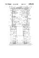
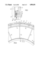
- FIG. 1 shows a longitudinal section according to line I--I in FIG. 2 through a vertically arranged spindle press constructed as a pulp press,
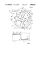
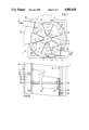
- FIG. 2 shows a top view of the spindle press according to line II--II in FIG. 1,
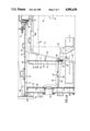
- FIG. 3 shows a view, according to line III--III in FIG. 2, of a portion of the spindle press without screen casing, in an enlarged view,
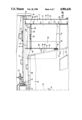
- FIGS. 4A and 4B show the upper portion of FIG. 1 in an enlarged view
- FIG. 5 shows the detail V in FIG. 4A in an enlarged view
- FIG. 6 shows a view according to line VI--VI in FIG. 1 in an enlarged view
- FIG. 7 shows a top view, corresponding to FIG. 2, of another embodiment form of the spindle press with two filling openings,
- FIG. 8 shows a partial longitudinal section through the head of another spindle press
- FIG. 9 shows a partial longitudinal section through the head of another spindle press.
- a spindle press 1 which is constructed as a pulp press, comprises a housing 2 with a circular cylindrical upper part 3 and a lower part 4 which are screwed together along a plane 5.
- the lower part 4 rests on a vertical frame 6 so as to be fixed with respect to rotation and is screwed with this along a plane 7.
- the vertical frame 6 is fastened at a foundation 8 which rests on a base 9.
- the cover 11 carries an upper bearing 16, which is adjustable in the radial direction with respect to a longitudinal axis 15 of the spindle press 1 by means of an adjusting mechanism 14, in which a shaft end 17 of a press spindle 18 is supported so as to be rotatable.
- the cover 11 is enclosed by a railing 19 fastened at the upper part 3.
- the press spindle 18 is rotatably supported at the bottom in a lower bearing 20 of the lower part 4, which lower bearing 20 is constructed as a ball bearing slewing connection, and is drivable so as to rotate by means of a drive arrangement 21 arranged in the vertical frame 6.
- the upper part 3 of the housing 2 comprises a spray casing 22, which is divided into axially successive sections, and a screen casing 23 which is arranged within the spray casing 22 and is likewise divided into axially successive sections.
- a first annular space 24 is provided between the spray casing 22 and the screen wall 23 for guiding out fluid which is pressed out of the sugar beet pulp and passes out through screen holes, not shown in FIG. 1, through the screen casing 23.
- the screen casing is provided with such screen holes from the compressor blades 25 until the plane 5 (compare FIGS. 4A and 4B).
- the screen casing 23 is supported on the outside at supporting rings 26 which are arranged at an axial distance from one another and are held in turn by comb-like plates 27 which extend parallel to the axis, are arranged at a distance from one another in the circumferential direction and fastened at an inner surface of the spray casing 22 (compare also FIG. 6).
- Interruptors 28, which extend radially inward until the vicinity of a spindle body 29 of the press spindle 18, are inserted into receiving openings of the upper part 3 from the outside in a plurality of vertical planes.
- the radial extension of the interruptors 28 decreases from the top to the bottom in the same way that the cross-sectional surface area of the spindle body 29 increases from an upper feed side 30 of the spindle press 1 to its lower outlet side 31.
- the first annular space 24 is connected with a dewatering mechanism 32 in the lower part 4.
- annular space 33 Between the screen casing 23 and the spindle body 29, there is a second annular space 33, in which an annular wall 34 extends from the top proceeding from the plane 10.
- the annular wall 34 thus encloses an upper end area of the spindle body 29 and is welded with the screen casing 23 by means of external web plates 35 (see also FIGS. 4A, 4B and 6).
- An annular seal 36 which prevents material to be pressed and fluid from penetrating upward into a wedgeshaped annular space 37 between the upper end area of the spindle body 29 and the annular wall 34, is provided between the spindle body 29 and the annular wall 34.
- FIG. 5 shows details of the annular seal 36.
- the second annular space 33 is defined at the top by a front wall 38 which is constructed in the manner of a screw and welded on the outside with the screen casing 23 so as to be tight and on the inside with the annular wall 34, also so as to be tight.
- the front wall 38 is composed of a screw part 39 produced from sheet metal and a connection part 40 which likewise consists of sheet metal.
- the upper part 3 comprises a rectangular filling opening 41 through which wet pulp is fed into the second annular space 33.
- the screw part 39 extends in a rotating direction 43 of the press spindle 18 from an axial end 42 of the filling opening 41 on the feed side until an axial end 44 of the filling opening 41 on the outlet side.
- the start 45 of the screw part 39 on the feed side is connected with an end 46 of the screw part 39 on the outlet side by means of the connection part 40 so as to be tight.
- the connection part 40 is arranged in a plane extending through the longitudinal axis 15.
- the screen casing 23 does not comprise any holes for the passage of pressed out fluid in the area between the compressor blades 25 and the front wall 38.
- the compressor blades 25 are fastened internally at the spindle body 29.
- the spindle body 29 is also only provided with perforations 47 for the passage of pressed out fluid from the compressor blades 25 downwards.
- Observation windows 48 are provided in the screw part 39 which are aligned with the observation openings 13 in the cover 11 in an axial direction.
- Observation windows 49 are also inserted in the upper part 3, only one of which is drawn in FIG. 1, specifically, so as to be offset in the circumferential direction.
- the observation windows 49 make it possible to see into the second annular space 33 below the front wall 38 from the side.
- a work platform 50 which extends along approximately one third of the circumference, is fastened at the outside of the upper part 3 (compare FIG. 2).
- the spindle body 29 is hollow and comprises an interior space 51 in which the perforations 47 allow pressed out fluid to pass through.
- the interior space 51 ends at the bottom in an annular duct 52 which is open at the top.
- the annular duct 52 is defined by means of an annular base 53 of the spindle body 29, a ring 54 of a central base connection piece 55 of the spindle body 29, which ring 54 extends upward beyond the base 53, and a side wall 56 of the spindle body 29.
- the base 53 comprises outlet connection pieces 57 arranged on a circle which is concentric with the longitudinal axis 15 of the spindle press 1.
- the base connection piece 55 is connected with an inner ring of the lower bearing and with a telescoping drive pipe 58 which extends in the downward direction.
- An upper pipe 59 and a lower pipe 60 of the drive pipe 58 are connected with one another by means of a tooth coupling 61.
- the lower pipe 60 is screwed along a plane 62 with a drive connection piece 63 which is rotatably supported in a drive bearing 64.
- the drive connection piece 63 carries a toothed ring 65 on the outside, with which pinions 66 of stationary drives 67 mesh.
- the outlet connection pieces 57 open into the dewatering arrangement 32.
- Manholes 68 are provided in the spindle body 29 at the top.
- the spindle body 29 carries worm wings 69 which extend outward at least approximately in contact with the screen casing 23 and whose slope and axial distance from one another decrease from the feed side 30 to the outlet side 31.
- a retaining ring 70 which projects outward radially over the side wall 56 and which defines an outlet annular gap 71 for the pressed pulp with the screen casing 23, is screwed on at the lower side of the base 53.
- the pressed pulp falls into an annular space 72 of the lower part 4, in which clearing wings 73 circulate, the clearing wings 73 being fastened at the lower side of the base 53.
- Diametrically opposed fall-out openings 75 which respectively deliver the pressed pulp into a fall shaft 76, are arranged in an annular plate 74 of the lower part 4.
- FIG. 2 shows a top view of the circular arc shape of the filling opening 41 between an outer end point of the connection part 40 and a point 77.
- the shape of the filling opening 41 which is rectangular as seen from the side, can be seen in FIGS. 1, 4A and 4B.
- a filling connection piece 78 which passes into a circular cross-sectional shape until its flange 79, extends tangentially outward from the filling opening 41.
- a tubular tamping worm 80 with which the wet pulp is fed under pressure in the direction of the arrow 81, is connected at the flange 79.
- FIG. 3 shows how the screw part 39 and the connection part 40 are fastened to one another so as to be tight on the one hand, and to the annular wall 34 on the other hand by means of welding. Two of the web plates 35 are also seen above the screw part 39.
- a reinforcing ring 82 which extends radially inward, is welded on at the inside of the annular wall 34.
- the perforations 47 in the spindle body 29 start downward from the plane of the compressor blades 25.
- the screen casing 23 is also provided with holes 83 for the passage of pressed out fluid only downward from the compressor blades 25. Condensation forming above the screw part 39 can flow off through dewatering holes 84 in the annular wall 34 and dewatering holes 85 in the screen casing 23 which are respectively provided directly above the screw part 39. The condensation then flows into the wedge-shaped annular space 37 on the one hand and into the first annular space 24 on the other hand.
- additional dewatering holes 86 are located directly above the annular seal 36 in the spindle body 29 and as a continuation in a supporting ring 87 for the annular seal 36, which supporting ring 87 is welded on externally on the spindle body 29.
- the annular seal 36 consists of the plastics material known under the trademark Teflon and is embedded in the supporting ring 87 in a dovetail connection and fastened at the supporting ring 87 with countersunk screws 88.
- the annular seal 36 slides externally on a sliding ring 89 consisting of stainless steel which is welded into the annular wall 34 at the bottom and inside. Condensation which collects in the wedge-shaped annular space 37 can flow off without pressure through the dewatering holes 86 into the interior space 51.
- FIG. 6 shows details of the upper end of the upper part 3.
- An assembly flange 90 is welded on at the spray casing 22 at the top.
- the embodiment form of the spindle press 1 shown in the aforementioned drawings operates as follows: when started, wet pulp is fed by means of the tamping worm 80, according to FIG. 2, and the filling connection piece 78 of the filling opening 41, through which the wet pulp falls downward into the second annular space 33.
- the retaining ring 70 (FIG. 1) prevents the pulp from falling directly into the annular space 72 through the outlet annular gap 71.
- the press spindle 18 rotates, the second annular space 33 fills up increasingly with pulp material until the latter reaches the lower side of the helically constructed front wall 38. From this moment on, with the continued rotation of the press spindle 18, a mechanical compression of the wet pulp begins in the second annular space 33 above the compressor blades 25.
- the pressed out fluid passes outward into the first annular space 24 of the housing 2 and into the interior space 51 of the spindle body 29 and flows in both cases through the dewatering arrangement 32.
- the pressed pulp achieves an especially high amount of dry substance by means of this special pressure treatment and compression at the outlet annular gap 71. This is also a result of the fact that there are no holes for the passage of pressed out fluid in the area of the screen casing 23 located opposite the helically constructed front wall 38. This promotes the pressure increase in this precompression zone.
- the spindle press comprises another filling opening 91 which is arranged so as to be diametrically opposite the filling opening 41.
- a tangential filling connection piece 92 which is fed with wet pulp through a tubular tamping worm 93 in the direction of the arrow 94, is connected to the additional filling opening 91.
- the screw part 39 extends only in the rotational
- connection part 40 along 180° from the connection part 40 to an additional connection part 95 which is arranged so as to be diametrical to the connection part 40.
- Another screw part 96 extends in the rotational direction 43 from an end of the additional connection part 95 on the feed side to an end of the connection part 40 on the outlet side.
- the screw parts 39 and 96 form a "double thread" in a certain way.
- the upper part 3 can also be provided with more than the two filling openings 41 and 91.
- the helically constructed front wall 38 would then have a "multiple thread” in a corresponding manner. A more uniform distribution of the pressure increase along the circumference of the spindle press 1 can then be achieved by means of this "multiple thread" construction.
- the front wall 38 which can be constructed in the aforementioned manner as a "single thread” or “multiple thread” and is provided with a connection part, not shown in FIG. 8, per “thread", comprises a helical sliding ring 97 inside.
- the sliding ring 97 also extends along at least one connection part, not shown in FIG. 8, and has a radial sealing contact with a gasket 98 which is circular cylindrical at least externally.
- the gasket 98 is fastened with countersunk screws 99 at a part of the spindle body 29 on the feed side and extends in an axial direction along the entire "stroke" of the front wall 38.
- the gasket 98 can consist of the plastics material known under the trademark Teflon.
- FIG. 9 shows another embodiment form of the spindle press 1 in which the front wall 38 carries a helical sealing strip 100 on the inside which can consist, for example, of the plastics material known under the trademark Teflon.
- the sealing strip 100 also extends along the inner edge of at least one connection part of the front wall 38, not shown in FIG. 9, and is fastened with countersunk screws 101 at a coaxial helical plate 102 of the front wall 38.
- the sealing strip 100 has a sealing contact with a circular cylindrical outer surface 103 at the end of the spindle body 29 on the feed side.
Landscapes
- Engineering & Computer Science (AREA)
- Mechanical Engineering (AREA)
- Press Drives And Press Lines (AREA)
- Paper (AREA)
- Materials For Medical Uses (AREA)
- Filtration Of Liquid (AREA)
- Processing Of Solid Wastes (AREA)
- Processing And Handling Of Plastics And Other Materials For Molding In General (AREA)
- Structures Of Non-Positive Displacement Pumps (AREA)
- Measuring Volume Flow (AREA)
- Gear Transmission (AREA)
- Gears, Cams (AREA)
Applications Claiming Priority (2)
| Application Number | Priority Date | Filing Date | Title |
|---|---|---|---|
| DE19863641248 DE3641248A1 (de) | 1986-12-03 | 1986-12-03 | Spindelpresse |
| DE3641248 | 1986-12-03 |
Publications (1)
| Publication Number | Publication Date |
|---|---|
| US4901636A true US4901636A (en) | 1990-02-20 |
Family
ID=6315334
Family Applications (1)
| Application Number | Title | Priority Date | Filing Date |
|---|---|---|---|
| US07/252,271 Expired - Fee Related US4901636A (en) | 1986-12-03 | 1987-11-04 | Spindle press |
Country Status (12)
| Country | Link |
|---|---|
| US (1) | US4901636A (de) |
| EP (1) | EP0293409B1 (de) |
| AT (1) | ATE47089T1 (de) |
| BG (1) | BG48209A3 (de) |
| DD (1) | DD264646A5 (de) |
| DE (2) | DE3641248A1 (de) |
| ES (1) | ES2005714A6 (de) |
| NO (1) | NO165666C (de) |
| RO (1) | RO102682B1 (de) |
| SU (1) | SU1831432A3 (de) |
| WO (1) | WO1988004232A1 (de) |
| YU (1) | YU214587A (de) |
Cited By (2)
| Publication number | Priority date | Publication date | Assignee | Title |
|---|---|---|---|---|
| US5099777A (en) * | 1990-07-23 | 1992-03-31 | Brother Kogyo Kabushiki Kaisha | Sewing operation procedure display apparatus for sewing machine |
| US20100314304A1 (en) * | 2009-06-16 | 2010-12-16 | Tapp Floyd G | Method and apparatus for separating and dewatering slurries |
Families Citing this family (1)
| Publication number | Priority date | Publication date | Assignee | Title |
|---|---|---|---|---|
| AT515482B1 (de) * | 2014-03-14 | 2016-03-15 | Andritz Ag Maschf | Schneckenpresse |
Citations (12)
| Publication number | Priority date | Publication date | Assignee | Title |
|---|---|---|---|---|
| DE95086C (de) * | ||||
| DE65165C (de) * | R. BERGREEN in Roitzsch bei Bitterfeld | Schnitzelpresse | ||
| US1354528A (en) * | 1916-12-22 | 1920-10-05 | Larrowe Milling Company | Pulp-press |
| US2664814A (en) * | 1948-02-21 | 1954-01-05 | Jackson & Church Company | Pulp press |
| US2709957A (en) * | 1953-01-16 | 1955-06-07 | Jackson & Church Company | Screen and frame structure with frame functioning as a torque tube |
| US2747499A (en) * | 1953-01-16 | 1956-05-29 | Jackson & Church Company | Discharge structure for a pulp press |
| US2775191A (en) * | 1954-02-08 | 1956-12-25 | Hawaiian Pineapple Co Ltd | Press |
| US3426677A (en) * | 1966-09-20 | 1969-02-11 | Wascon Systems Inc | Screw press |
| US3478679A (en) * | 1967-05-24 | 1969-11-18 | Stearns Roger Corp | Pulp deliquifying press |
| DE2160585A1 (de) * | 1971-12-07 | 1973-06-20 | Lajos Alfoeldi | Schnitzelpresse mit zentraleinlauf |
| FR2255168A1 (de) * | 1973-12-22 | 1975-07-18 | Salzgitter Maschinen Ag | |
| DE2641597A1 (de) * | 1976-09-16 | 1978-03-30 | Selwig & Lange Maschf | Spindelschneckenpresse |
Family Cites Families (2)
| Publication number | Priority date | Publication date | Assignee | Title |
|---|---|---|---|---|
| GB803216A (en) * | 1956-11-06 | 1958-10-22 | Landsverk Ab | Improvements in or relating to vertical screw presses for pressing liquid from vegetable material |
| FR2258259A1 (en) * | 1974-01-21 | 1975-08-18 | Coq France | Wine making screw press with pumped infeed - for continuous process offering higher quality than gravity or worm in feed |
-
1986
- 1986-12-03 DE DE19863641248 patent/DE3641248A1/de not_active Withdrawn
-
1987
- 1987-11-04 EP EP87907320A patent/EP0293409B1/de not_active Expired
- 1987-11-04 WO PCT/EP1987/000670 patent/WO1988004232A1/de not_active Ceased
- 1987-11-04 US US07/252,271 patent/US4901636A/en not_active Expired - Fee Related
- 1987-11-04 AT AT87907320T patent/ATE47089T1/de active
- 1987-11-04 DE DE8787907320T patent/DE3760717D1/de not_active Expired
- 1987-11-04 RO RO1987134755A patent/RO102682B1/ro unknown
- 1987-11-26 YU YU02145/87A patent/YU214587A/xx unknown
- 1987-11-30 DD DD87309658A patent/DD264646A5/de not_active IP Right Cessation
- 1987-12-02 ES ES8703444A patent/ES2005714A6/es not_active Expired
-
1988
- 1988-08-02 NO NO883425A patent/NO165666C/no unknown
- 1988-08-02 SU SU884356207A patent/SU1831432A3/ru active
- 1988-08-30 BG BG085331A patent/BG48209A3/xx unknown
Patent Citations (13)
| Publication number | Priority date | Publication date | Assignee | Title |
|---|---|---|---|---|
| DE95086C (de) * | ||||
| DE65165C (de) * | R. BERGREEN in Roitzsch bei Bitterfeld | Schnitzelpresse | ||
| US1354528A (en) * | 1916-12-22 | 1920-10-05 | Larrowe Milling Company | Pulp-press |
| US2664814A (en) * | 1948-02-21 | 1954-01-05 | Jackson & Church Company | Pulp press |
| US2709957A (en) * | 1953-01-16 | 1955-06-07 | Jackson & Church Company | Screen and frame structure with frame functioning as a torque tube |
| US2747499A (en) * | 1953-01-16 | 1956-05-29 | Jackson & Church Company | Discharge structure for a pulp press |
| US2775191A (en) * | 1954-02-08 | 1956-12-25 | Hawaiian Pineapple Co Ltd | Press |
| US3426677A (en) * | 1966-09-20 | 1969-02-11 | Wascon Systems Inc | Screw press |
| US3478679A (en) * | 1967-05-24 | 1969-11-18 | Stearns Roger Corp | Pulp deliquifying press |
| DE2160585A1 (de) * | 1971-12-07 | 1973-06-20 | Lajos Alfoeldi | Schnitzelpresse mit zentraleinlauf |
| FR2255168A1 (de) * | 1973-12-22 | 1975-07-18 | Salzgitter Maschinen Ag | |
| US3998148A (en) * | 1973-12-22 | 1976-12-21 | Salzgitter Maschinen Aktiengesellschaft | Press for sugar beet and similar chips |
| DE2641597A1 (de) * | 1976-09-16 | 1978-03-30 | Selwig & Lange Maschf | Spindelschneckenpresse |
Cited By (3)
| Publication number | Priority date | Publication date | Assignee | Title |
|---|---|---|---|---|
| US5099777A (en) * | 1990-07-23 | 1992-03-31 | Brother Kogyo Kabushiki Kaisha | Sewing operation procedure display apparatus for sewing machine |
| US20100314304A1 (en) * | 2009-06-16 | 2010-12-16 | Tapp Floyd G | Method and apparatus for separating and dewatering slurries |
| US8025156B2 (en) * | 2009-06-16 | 2011-09-27 | Tapp Floyd G | Method and apparatus for separating and dewatering slurries |
Also Published As
| Publication number | Publication date |
|---|---|
| NO165666C (no) | 1991-03-20 |
| NO165666B (no) | 1990-12-10 |
| RO102682B1 (en) | 1993-03-01 |
| NO883425L (no) | 1988-08-02 |
| ES2005714A6 (es) | 1989-03-16 |
| YU214587A (en) | 1990-10-31 |
| EP0293409A1 (de) | 1988-12-07 |
| BG48209A3 (en) | 1990-12-14 |
| ATE47089T1 (de) | 1989-10-15 |
| DE3641248A1 (de) | 1988-07-28 |
| EP0293409B1 (de) | 1989-10-11 |
| WO1988004232A1 (fr) | 1988-06-16 |
| DD264646A5 (de) | 1989-02-08 |
| NO883425D0 (no) | 1988-08-02 |
| SU1831432A3 (en) | 1993-07-30 |
| DE3760717D1 (en) | 1989-11-16 |
Similar Documents
| Publication | Publication Date | Title |
|---|---|---|
| FI93330C (fi) | Menetelmä ja laite veden poistamiseksi materiaalista sekä tämän puristamiseksi | |
| AU2006200347A1 (en) | Compression Screw with Combination Single and Double Flights | |
| US4901636A (en) | Spindle press | |
| US6588331B2 (en) | Screw press inlet section | |
| CA1110979A (en) | Device for the separation of liquid from a slurryladen fluid | |
| WO1987003652A1 (en) | Device for pumping highly-viscous material, in particular thick oil | |
| US7152522B2 (en) | Screw press with radial gate valve and supported screw shaft | |
| EP1423037B1 (de) | Fruchtpresse | |
| US1613553A (en) | Seed separator | |
| US3527158A (en) | Positive displacement press | |
| JP3456603B2 (ja) | 脱水機 | |
| EP0296184A1 (de) | Schneckenspindelpresse. | |
| CN213227683U (zh) | 进料端挡料组件 | |
| RU2027607C1 (ru) | Подпрессовщик брикетного пресса | |
| CN212937299U (zh) | 一种撒料均匀的倒装分离型桶式撒料装置 | |
| US3270663A (en) | Screen plate for pulp press and the like | |
| CN111959015A (zh) | 湿垃圾螺旋挤压机 | |
| US4974506A (en) | Spindle press | |
| US3892173A (en) | Horizontal screw press | |
| CN218583575U (zh) | 一种多功能脱水机 | |
| CN213261218U (zh) | 保压组件 | |
| CN213261217U (zh) | 湿垃圾螺旋挤压机 | |
| CN212242296U (zh) | 一种双螺旋挤压脱水机 | |
| US2697978A (en) | Apparatus for extracting liquid from liquid-bearing material | |
| CN218559893U (zh) | 一种粉料钢板仓 |
Legal Events
| Date | Code | Title | Description |
|---|---|---|---|
| AS | Assignment |
Owner name: SALZGITTER MASCHINENBAU GMBH, WINDMUHLENBERGSTRASS Free format text: ASSIGNMENT OF ASSIGNORS INTEREST.;ASSIGNORS:TEGTMEYER, KURT;LUHRS, HERMANN;WERNER, WOLFGANG;REEL/FRAME:004969/0034 Effective date: 19881005 Owner name: SALZGITTER MASCHINENBAU GMBH, GERMANY Free format text: ASSIGNMENT OF ASSIGNORS INTEREST;ASSIGNORS:TEGTMEYER, KURT;LUHRS, HERMANN;WERNER, WOLFGANG;REEL/FRAME:004969/0034 Effective date: 19881005 |
|
| FEPP | Fee payment procedure |
Free format text: PAYOR NUMBER ASSIGNED (ORIGINAL EVENT CODE: ASPN); ENTITY STATUS OF PATENT OWNER: LARGE ENTITY |
|
| FPAY | Fee payment |
Year of fee payment: 4 |
|
| AS | Assignment |
Owner name: MSG MASCHINEN-SERVICE GMBH, GERMANY Free format text: CHANGE OF NAME;ASSIGNOR:SALZGITTER MASCHINENBAU GMBH;REEL/FRAME:006949/0565 Effective date: 19931121 |
|
| AS | Assignment |
Owner name: BRAUNSCHWEIGISCHE MASCHINENBAUANSTALT AG, GERMANY Free format text: ASSIGNMENT OF ASSIGNORS INTEREST;ASSIGNOR:MSG MASCHINEN-SERVICE GMBH;REEL/FRAME:007037/0383 Effective date: 19940509 |
|
| REMI | Maintenance fee reminder mailed | ||
| LAPS | Lapse for failure to pay maintenance fees | ||
| STCH | Information on status: patent discontinuation |
Free format text: PATENT EXPIRED DUE TO NONPAYMENT OF MAINTENANCE FEES UNDER 37 CFR 1.362 |