US4901526A - Bottom unit for the combustion chamber of a liquid-fueled rocket - Google Patents
Bottom unit for the combustion chamber of a liquid-fueled rocket Download PDFInfo
- Publication number
- US4901526A US4901526A US07/300,419 US30041989A US4901526A US 4901526 A US4901526 A US 4901526A US 30041989 A US30041989 A US 30041989A US 4901526 A US4901526 A US 4901526A
- Authority
- US
- United States
- Prior art keywords
- annular body
- bottom unit
- accordance
- combustion chamber
- center
- Prior art date
- Legal status (The legal status is an assumption and is not a legal conclusion. Google has not performed a legal analysis and makes no representation as to the accuracy of the status listed.)
- Expired - Fee Related
Links
- 238000002485 combustion reaction Methods 0.000 title claims abstract description 26
- 239000000446 fuel Substances 0.000 claims abstract description 15
- 239000013013 elastic material Substances 0.000 claims abstract description 10
- 238000002347 injection Methods 0.000 claims abstract description 10
- 239000007924 injection Substances 0.000 claims abstract description 10
- 229920002430 Fibre-reinforced plastic Polymers 0.000 claims description 3
- 239000011151 fibre-reinforced plastic Substances 0.000 claims description 3
- 239000000463 material Substances 0.000 claims description 3
- 239000002184 metal Substances 0.000 claims description 2
- 230000008901 benefit Effects 0.000 description 3
- 238000006073 displacement reaction Methods 0.000 description 2
- 230000004048 modification Effects 0.000 description 2
- 238000012986 modification Methods 0.000 description 2
- 229910000831 Steel Inorganic materials 0.000 description 1
- 230000008859 change Effects 0.000 description 1
- 238000013016 damping Methods 0.000 description 1
- 238000002955 isolation Methods 0.000 description 1
- 239000007788 liquid Substances 0.000 description 1
- 238000004519 manufacturing process Methods 0.000 description 1
- 230000007935 neutral effect Effects 0.000 description 1
- 230000008092 positive effect Effects 0.000 description 1
- 230000009467 reduction Effects 0.000 description 1
- 230000003014 reinforcing effect Effects 0.000 description 1
- 230000008439 repair process Effects 0.000 description 1
- 239000010959 steel Substances 0.000 description 1
- 230000007704 transition Effects 0.000 description 1
- 238000004073 vulcanization Methods 0.000 description 1
Images

Classifications
-
- F—MECHANICAL ENGINEERING; LIGHTING; HEATING; WEAPONS; BLASTING
- F02—COMBUSTION ENGINES; HOT-GAS OR COMBUSTION-PRODUCT ENGINE PLANTS
- F02K—JET-PROPULSION PLANTS
- F02K9/00—Rocket-engine plants, i.e. plants carrying both fuel and oxidant therefor; Control thereof
- F02K9/42—Rocket-engine plants, i.e. plants carrying both fuel and oxidant therefor; Control thereof using liquid or gaseous propellants
- F02K9/44—Feeding propellants
- F02K9/52—Injectors
-
- F—MECHANICAL ENGINEERING; LIGHTING; HEATING; WEAPONS; BLASTING
- F02—COMBUSTION ENGINES; HOT-GAS OR COMBUSTION-PRODUCT ENGINE PLANTS
- F02K—JET-PROPULSION PLANTS
- F02K9/00—Rocket-engine plants, i.e. plants carrying both fuel and oxidant therefor; Control thereof
- F02K9/42—Rocket-engine plants, i.e. plants carrying both fuel and oxidant therefor; Control thereof using liquid or gaseous propellants
- F02K9/44—Feeding propellants
-
- F—MECHANICAL ENGINEERING; LIGHTING; HEATING; WEAPONS; BLASTING
- F02—COMBUSTION ENGINES; HOT-GAS OR COMBUSTION-PRODUCT ENGINE PLANTS
- F02K—JET-PROPULSION PLANTS
- F02K9/00—Rocket-engine plants, i.e. plants carrying both fuel and oxidant therefor; Control thereof
- F02K9/80—Rocket-engine plants, i.e. plants carrying both fuel and oxidant therefor; Control thereof characterised by thrust or thrust vector control
- F02K9/84—Rocket-engine plants, i.e. plants carrying both fuel and oxidant therefor; Control thereof characterised by thrust or thrust vector control using movable nozzles
-
- F—MECHANICAL ENGINEERING; LIGHTING; HEATING; WEAPONS; BLASTING
- F16—ENGINEERING ELEMENTS AND UNITS; GENERAL MEASURES FOR PRODUCING AND MAINTAINING EFFECTIVE FUNCTIONING OF MACHINES OR INSTALLATIONS; THERMAL INSULATION IN GENERAL
- F16L—PIPES; JOINTS OR FITTINGS FOR PIPES; SUPPORTS FOR PIPES, CABLES OR PROTECTIVE TUBING; MEANS FOR THERMAL INSULATION IN GENERAL
- F16L27/00—Adjustable joints; Joints allowing movement
- F16L27/10—Adjustable joints; Joints allowing movement comprising a flexible connection only
- F16L27/103—Adjustable joints; Joints allowing movement comprising a flexible connection only in which a flexible element, e.g. a rubber-metal laminate, which undergoes constraints consisting of shear and flexure, is sandwiched between partly curved surfaces
Definitions
- the invention relates to a bottom unit for the combustion chamber of a liquid-fueled rocket.
- the bottom unit includes a bottom plate held on a swivel bearing which can be turned about an axis normal to the longitudinal axis of the rocket.
- the bottom unit has circumferentially distributed openings for the injection of the two fuel components. Two separate groups of supply passages are connected to the fuel injection openings to provide the liquid fuel.
- a rocket bottom unit of this general type is well known.
- the swivel bearing contained therein is a Cardan-joint and is more or less surrounded externally by the fuel component supply lines constituted by hoses.
- the overall structure of the bottom unit is accordingly complicated and difficult.
- the swivel bearing comprises a rigid thrust plate and a rigid hanger plate which are supported and fastened to one another by an internally located, first, inner annular body of rubber elastic material and a second, outer annular body of rubber elastic material surrounding the first annular body with a radial space.
- the one group of supply passages are formed by the cavity surrounded by the first annular body and the other group of supply passages are formed by the annular space between the first and second annular bodies.
- the supply passages are thus integrated into the swivel bearing eliminating the need for hoses and giving the overall design not only substantially greater functional clarity but also greater simplicity.
- the available flow cross section of the supply passages for the two fuel components is substantially increased in the space immediately preceding the injection orifices. This factor, taken in conjunction with the direct routing, contributes to the assurance of precisely defined and identical conditions of flow in the orifices. This results in an especially uniform burn in the combustion chamber.
- the annular bodies consisting of a rubber-elastic material produce a high degree of damping of the pulsating pressure changes produced in the supply lines as a result of the operation of the rocket. This too has a positive effect on the smoothness of burn in the combustion chamber. Such pulsating pressure changes can be due, for example, to backfiring in the combustion chamber.
- the isolation of the vibration of the combustion chamber from the rocket is substantially improved.
- first and second annular bodies to surround one another concentrically.
- Such swiveling movements serve to steer the rocket. They are generally limited to tilting the combustion chamber by less than about seven degrees about the center of rotation that is located along the central longtitudinal axis.
- the center of rotation is best disposed on the center line of the combustion chamber in the vicinity of its thrust-transferring surface, in which case a slight vertical distance from the bottom surface can be provided, if desired. Even under the conditions of the thrust produced on the bottom surface of the combustion chamber by launching the rocket, the center of rotation will not undergo any disturbing lateral displacement.
- At least the second annular body is provided with at least one reinforcing or stiffening insert disposed between the thrust plate and hanger plate.
- this insert has a hollow conical profile or a spherical profile, as required. The optimum is achieved, when the surface normals pass through the center of rotation. Undesirable deformations of the annular body can thus be suppressed and, consequently, the center of rotation of the swivel will remain in a stable position under severe operating conditions.
- the tilt angle of the combustion chamber can be increased but permanent deformation of the annular bodies can be avoided if a plurality of such stiffening inserts are used in the latter and are sandwiched together. Particularly good properties are obtained in this respect if the layers of the second annular body which consist of rubber elastic material are of relatively small thickness perpendicular to the direction of the contact surfaces. The ability of the bottom unit to tilt is accordingly also slight and can be increased if necessary by increasing the number of successive layers.
- the stiffening insert--it is best to use several inserts, alternating always with layers of a respective annular body--can be brought close to the exposed inner and/or outer surface of the annular body and covered by the latter while avoiding any appreciable unevenness of such surfaces. Any corrosive attack on the stiffening insert by the fuel components is thus prevented.
- the stiffening insert must be of such a nature that only those deformations of the annular bodies are prevented which can produce an undesirable shift of the center of rotation.
- stiffening inserts which consist of sheet metal or fiber-reinforced plastic, and to bond the thrust plate and the hanger plate to adjacent portions of the annular bodies by adhesion, for example by direct vulcanization.
- the annular body layers adjoining both sides of the stiffening insert are to have a greater width in the direction of the maximum dimension of the profile of the stiffening insert than perpendicular to this direction, preferably a width that is three to twenty times as great as perpendicular to this direction.
- the stability of the position of the center of rotation of the swivel bearing and hence the steerability of the rocket is especially good in this case.
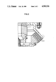
- FIG. 1 shows in detail a longitudinal section of the transition region between a liquid-fueled rocket and a corresponding combustion chamber.
- FIG. 2 shows a sectional detail of FIG. 1.
- a liquid-fueled rocket 18 is defined at the bottom by a flat surface 15 from which mounting bolts 19 project perpendicularly downward. These bolts serve to clamp a bottom unit against the flat surface, while compressing O-rings 20 that seal supply passages 16 and 17 of the two fuel components from one another and from the environment.
- the O-rings are contained in circumferential grooves which interrupt the flat surface 15 of the rocket 18.
- the bottom unit consists essentially of a swivel bearing 1 and a combustion chamber 21 which is pivotally supported by the bearing on the flat surface 15 of the rocket 18.
- the preferred embodiment of the swivel bearing 1 will initially be described. It comprises a thrust plate 5 and a hanger plate 6 which are supported and joined to one another by a first, inner annular body 7 of rubber elastic material and a second annular body 8 of rubber elastic material surrounding the first annular body at a radial distance.
- the surfaces in mutual contact between the two annular bodies 7 and 8 on the one hand, and the thrust plate and hanger plate 5, 6 on the other, are spherically curved about a common center of rotation 11. This center is disposed at the center of the base of the combustion chamber 21.
- stiffening inserts 12 are embedded in the second annular body 8, which are at a substantially uniform distance from one another and from the associated contact surfaces of the thrust plate 5 on the one hand and the hanger plate 6 on the other.
- the resulting layers 8.1, 8.2 . . . 8.n of the second annular body have a substantially greater width parallel to the direction of the stiffening inserts than perpendicular to this direction.
- the ratio in question amounts in the present case to about seven to ten.
- a ratio in the range of five to twelve assures, even in critical operating conditions, a relatively stable location of the center 11 while providing an effective means for steering the rocket.
- the stiffening inserts 12 preferably consist of sheet steel or fiber reinforced plastic.
- the bottom plate 2 of the combustion chamber 21 is fastened together with the hanger plate 6.
- the bottom plate 2 contains openings or orifices for the injection of the two fuel components. These openings are evenly distributed in the circumferential direction and their supply passages are interconnected in the one case by the cavity 9 of the first annular body 7 and in the other case by the space 10 between the first annular body 7 and the second annular body 8. They are thus connected to the supply passages 16 and 17, respectively, for the two fuel components.
Landscapes
- Engineering & Computer Science (AREA)
- General Engineering & Computer Science (AREA)
- Mechanical Engineering (AREA)
- Chemical & Material Sciences (AREA)
- Combustion & Propulsion (AREA)
- Support Of The Bearing (AREA)
- Toys (AREA)
Applications Claiming Priority (2)
| Application Number | Priority Date | Filing Date | Title |
|---|---|---|---|
| DE3802257 | 1988-01-27 | ||
| DE3802257A DE3802257C1 (https=) | 1988-01-27 | 1988-01-27 |
Publications (1)
| Publication Number | Publication Date |
|---|---|
| US4901526A true US4901526A (en) | 1990-02-20 |
Family
ID=6346025
Family Applications (1)
| Application Number | Title | Priority Date | Filing Date |
|---|---|---|---|
| US07/300,419 Expired - Fee Related US4901526A (en) | 1988-01-27 | 1989-01-23 | Bottom unit for the combustion chamber of a liquid-fueled rocket |
Country Status (3)
| Country | Link |
|---|---|
| US (1) | US4901526A (https=) |
| DE (1) | DE3802257C1 (https=) |
| FR (1) | FR2626317B1 (https=) |
Cited By (2)
| Publication number | Priority date | Publication date | Assignee | Title |
|---|---|---|---|---|
| US6138451A (en) * | 1998-05-11 | 2000-10-31 | Hughes Electronics Corporation | Rocket engine with combustion chamber step structure insert, and its fabrication |
| WO2011106446A1 (en) * | 2010-02-24 | 2011-09-01 | Innovative Defense, Llc | Packaged propellant air-induced variable thrust rocket engine |
Families Citing this family (1)
| Publication number | Priority date | Publication date | Assignee | Title |
|---|---|---|---|---|
| RU2126905C1 (ru) * | 1998-03-12 | 1999-02-27 | Федеральное государственное унитарное предприятие "Исследовательский центр им.М.В.Келдыша" | Камера сгорания |
Citations (7)
| Publication number | Priority date | Publication date | Assignee | Title |
|---|---|---|---|---|
| US3016697A (en) * | 1959-06-19 | 1962-01-16 | Curtiss Wright Corp | Rocket engine swivel mount |
| US3049877A (en) * | 1956-02-13 | 1962-08-21 | Thiokol Chemical Corp | Nozzle for reaction motor |
| US3138922A (en) * | 1962-01-22 | 1964-06-30 | Buehler Corp | Rotating conduit control |
| US3140584A (en) * | 1959-05-07 | 1964-07-14 | Thiokol Chemical Corp | Steering device for rocket-powered vehicles |
| US3145530A (en) * | 1962-09-27 | 1964-08-25 | Gen Motors Corp | Multistage rocket |
| US3159969A (en) * | 1962-03-20 | 1964-12-08 | Snecma | Sealing and rotatable mounting arrangement for rocket nozzles |
| US3280563A (en) * | 1962-10-26 | 1966-10-25 | Charles F Bowersett | Thrust vectoring system |
Family Cites Families (6)
| Publication number | Priority date | Publication date | Assignee | Title |
|---|---|---|---|---|
| US3659423A (en) * | 1964-09-17 | 1972-05-02 | Goodyear Aerospace Corp | Moveable rocket |
| GB1189052A (en) * | 1968-01-09 | 1970-04-22 | Lockheed Aircraft Corp | Flexible Joint Means |
| FR2034339B1 (https=) * | 1969-03-18 | 1974-12-06 | Bringer Henri | |
| US3958840A (en) * | 1975-05-05 | 1976-05-25 | Thiokol Corporation | Flexible bearing having reinforcements |
| US3941433A (en) * | 1975-05-05 | 1976-03-02 | Thiokol Corporation | Flexible bearing having low torque resistance |
| US4103939A (en) * | 1976-06-15 | 1978-08-01 | Murdock Machine & Engineering Company | Multi passage flexible connector |
-
1988
- 1988-01-27 DE DE3802257A patent/DE3802257C1/de not_active Expired
-
1989
- 1989-01-09 FR FR898900149A patent/FR2626317B1/fr not_active Expired - Fee Related
- 1989-01-23 US US07/300,419 patent/US4901526A/en not_active Expired - Fee Related
Patent Citations (7)
| Publication number | Priority date | Publication date | Assignee | Title |
|---|---|---|---|---|
| US3049877A (en) * | 1956-02-13 | 1962-08-21 | Thiokol Chemical Corp | Nozzle for reaction motor |
| US3140584A (en) * | 1959-05-07 | 1964-07-14 | Thiokol Chemical Corp | Steering device for rocket-powered vehicles |
| US3016697A (en) * | 1959-06-19 | 1962-01-16 | Curtiss Wright Corp | Rocket engine swivel mount |
| US3138922A (en) * | 1962-01-22 | 1964-06-30 | Buehler Corp | Rotating conduit control |
| US3159969A (en) * | 1962-03-20 | 1964-12-08 | Snecma | Sealing and rotatable mounting arrangement for rocket nozzles |
| US3145530A (en) * | 1962-09-27 | 1964-08-25 | Gen Motors Corp | Multistage rocket |
| US3280563A (en) * | 1962-10-26 | 1966-10-25 | Charles F Bowersett | Thrust vectoring system |
Cited By (6)
| Publication number | Priority date | Publication date | Assignee | Title |
|---|---|---|---|---|
| US6138451A (en) * | 1998-05-11 | 2000-10-31 | Hughes Electronics Corporation | Rocket engine with combustion chamber step structure insert, and its fabrication |
| WO2011106446A1 (en) * | 2010-02-24 | 2011-09-01 | Innovative Defense, Llc | Packaged propellant air-induced variable thrust rocket engine |
| CN102971519A (zh) * | 2010-02-24 | 2013-03-13 | 创新防卫设施有限责任公司 | 封装推进剂的引气式可变推力火箭发动机 |
| RU2564728C2 (ru) * | 2010-02-24 | 2015-10-10 | ИННЭВЭЙТИВ ДИФЕНС, ЭлЭлСи | Воздушно-реактивный двигатель с регулируемой тягой, использующий пакетированное топливо |
| CN102971519B (zh) * | 2010-02-24 | 2016-04-27 | 创新防卫设施有限责任公司 | 火箭推进装置以及向火箭推进装置产生主动推力的方法 |
| US9410503B2 (en) | 2010-02-24 | 2016-08-09 | Innovative Defense, Llc | Packaged propellant air-induced variable thrust rocket engine |
Also Published As
| Publication number | Publication date |
|---|---|
| FR2626317B1 (fr) | 1994-06-17 |
| DE3802257C1 (https=) | 1989-07-20 |
| FR2626317A1 (fr) | 1989-07-28 |
Similar Documents
| Publication | Publication Date | Title |
|---|---|---|
| US4968010A (en) | Slotted disc and elastomeric matrix damper assembly | |
| US3869151A (en) | Internally supported flexible duct joint | |
| US3422848A (en) | Multiport rotary disc valve with liner protection means | |
| US3390899A (en) | Flexible joint means | |
| US3747963A (en) | High vacuum flange assembly with o-ring gasket | |
| US5743170A (en) | Diaphragm mechanism for an air driven diaphragm pump | |
| CN111365144B (zh) | 一种柔性接头及采用该柔性接头的固体火箭发动机喷管 | |
| US3958840A (en) | Flexible bearing having reinforcements | |
| US4901526A (en) | Bottom unit for the combustion chamber of a liquid-fueled rocket | |
| US3504902A (en) | Pin stabilized laminated bearing flexible joint | |
| JPH03321A (ja) | 可撓性ダイヤフラムを含む可撓性カップリング | |
| US4013030A (en) | Support for LNG ship tanks | |
| US4895354A (en) | Equalizing stress distribution in each laminate of an asymmetrically loaded elastomeric bearing | |
| US4311313A (en) | Clearance sealing arrangement for jet thrust deflection equipment | |
| US3504904A (en) | Retainer ring button laminated bearing flexible joint | |
| US4772033A (en) | Flexible duct joint utilizing lip in recess in a flange | |
| US5024120A (en) | Torsional vibration damper with an undulating damping ring | |
| US5297874A (en) | Elastomeric bearing | |
| CN1268833C (zh) | 汽轮机或燃气轮机的壳体 | |
| EP0226845B1 (en) | Single component seal | |
| EP0642635B1 (en) | A fly wheel arrangement | |
| US2168131A (en) | Internal combustion engine | |
| US3381986A (en) | Frictionless coupling | |
| US6923108B2 (en) | Composite diaphragm for diaphragm pumps | |
| CA2326790C (en) | System for activating a steerable thrust-vectoring nozzle for a jet propulsion system using several circumferentially distributed elastic assemblies |
Legal Events
| Date | Code | Title | Description |
|---|---|---|---|
| AS | Assignment |
Owner name: FIRMA CARL FREUDENBERG, GERMANY Free format text: ASSIGNMENT OF ASSIGNORS INTEREST.;ASSIGNORS:BARTH, THOMAS;KELLER, HEINZ;REEL/FRAME:005028/0567 Effective date: 19890110 |
|
| REMI | Maintenance fee reminder mailed | ||
| LAPS | Lapse for failure to pay maintenance fees | ||
| FP | Lapsed due to failure to pay maintenance fee |
Effective date: 19980225 |
|
| STCH | Information on status: patent discontinuation |
Free format text: PATENT EXPIRED DUE TO NONPAYMENT OF MAINTENANCE FEES UNDER 37 CFR 1.362 |