US4901522A - Turbojet engine combustion chamber with a double wall converging zone - Google Patents
Turbojet engine combustion chamber with a double wall converging zone Download PDFInfo
- Publication number
- US4901522A US4901522A US07/281,749 US28174988A US4901522A US 4901522 A US4901522 A US 4901522A US 28174988 A US28174988 A US 28174988A US 4901522 A US4901522 A US 4901522A
- Authority
- US
- United States
- Prior art keywords
- flanges
- wall
- combustion chamber
- hot
- cold
- Prior art date
- Legal status (The legal status is an assumption and is not a legal conclusion. Google has not performed a legal analysis and makes no representation as to the accuracy of the status listed.)
- Expired - Lifetime
Links
- 238000002485 combustion reaction Methods 0.000 title claims abstract description 42
- 238000001816 cooling Methods 0.000 claims abstract description 37
- 238000011144 upstream manufacturing Methods 0.000 claims abstract description 16
- 238000010790 dilution Methods 0.000 claims description 8
- 239000012895 dilution Substances 0.000 claims description 8
- 230000000717 retained effect Effects 0.000 abstract description 6
- 230000008602 contraction Effects 0.000 abstract description 3
- 239000000567 combustion gas Substances 0.000 description 6
- 239000000446 fuel Substances 0.000 description 6
- 239000007789 gas Substances 0.000 description 4
- 230000006835 compression Effects 0.000 description 2
- 238000007906 compression Methods 0.000 description 2
- 239000000203 mixture Substances 0.000 description 2
- 238000010276 construction Methods 0.000 description 1
- 230000003247 decreasing effect Effects 0.000 description 1
- 238000003780 insertion Methods 0.000 description 1
- 230000037431 insertion Effects 0.000 description 1
- 238000012423 maintenance Methods 0.000 description 1
- 230000002093 peripheral effect Effects 0.000 description 1
Images

Classifications
-
- F—MECHANICAL ENGINEERING; LIGHTING; HEATING; WEAPONS; BLASTING
- F23—COMBUSTION APPARATUS; COMBUSTION PROCESSES
- F23R—GENERATING COMBUSTION PRODUCTS OF HIGH PRESSURE OR HIGH VELOCITY, e.g. GAS-TURBINE COMBUSTION CHAMBERS
- F23R3/00—Continuous combustion chambers using liquid or gaseous fuel
- F23R3/02—Continuous combustion chambers using liquid or gaseous fuel characterised by the air-flow or gas-flow configuration
- F23R3/04—Air inlet arrangements
- F23R3/06—Arrangement of apertures along the flame tube
- F23R3/08—Arrangement of apertures along the flame tube between annular flame tube sections, e.g. flame tubes with telescopic sections
-
- F—MECHANICAL ENGINEERING; LIGHTING; HEATING; WEAPONS; BLASTING
- F23—COMBUSTION APPARATUS; COMBUSTION PROCESSES
- F23R—GENERATING COMBUSTION PRODUCTS OF HIGH PRESSURE OR HIGH VELOCITY, e.g. GAS-TURBINE COMBUSTION CHAMBERS
- F23R3/00—Continuous combustion chambers using liquid or gaseous fuel
- F23R3/002—Wall structures
-
- F—MECHANICAL ENGINEERING; LIGHTING; HEATING; WEAPONS; BLASTING
- F05—INDEXING SCHEMES RELATING TO ENGINES OR PUMPS IN VARIOUS SUBCLASSES OF CLASSES F01-F04
- F05B—INDEXING SCHEME RELATING TO WIND, SPRING, WEIGHT, INERTIA OR LIKE MOTORS, TO MACHINES OR ENGINES FOR LIQUIDS COVERED BY SUBCLASSES F03B, F03D AND F03G
- F05B2260/00—Function
- F05B2260/20—Heat transfer, e.g. cooling
- F05B2260/201—Heat transfer, e.g. cooling by impingement of a fluid
-
- F—MECHANICAL ENGINEERING; LIGHTING; HEATING; WEAPONS; BLASTING
- F05—INDEXING SCHEMES RELATING TO ENGINES OR PUMPS IN VARIOUS SUBCLASSES OF CLASSES F01-F04
- F05B—INDEXING SCHEME RELATING TO WIND, SPRING, WEIGHT, INERTIA OR LIKE MOTORS, TO MACHINES OR ENGINES FOR LIQUIDS COVERED BY SUBCLASSES F03B, F03D AND F03G
- F05B2260/00—Function
- F05B2260/20—Heat transfer, e.g. cooling
- F05B2260/202—Heat transfer, e.g. cooling by film cooling
-
- Y—GENERAL TAGGING OF NEW TECHNOLOGICAL DEVELOPMENTS; GENERAL TAGGING OF CROSS-SECTIONAL TECHNOLOGIES SPANNING OVER SEVERAL SECTIONS OF THE IPC; TECHNICAL SUBJECTS COVERED BY FORMER USPC CROSS-REFERENCE ART COLLECTIONS [XRACs] AND DIGESTS
- Y02—TECHNOLOGIES OR APPLICATIONS FOR MITIGATION OR ADAPTATION AGAINST CLIMATE CHANGE
- Y02T—CLIMATE CHANGE MITIGATION TECHNOLOGIES RELATED TO TRANSPORTATION
- Y02T50/00—Aeronautics or air transport
- Y02T50/60—Efficient propulsion technologies, e.g. for aircraft
Definitions
- the present invention relates to combustion chambers for aircraft type turbojet engines, specifically such combustion chambers having a generally annular configuration with a double walled converging zone.
- combustion chambers While the increased operating temperatures and the increased compression ratios have provided jet engines with improved performance and specific fuel consumption figures, the structure of the combustion chambers has had to be modified to obtain the necessary strength and the requisite service life.
- the combustion chambers are typically designed to incorporate double thickness walls on both the inner and outer annular boundary walls so as to provide the necessary cooling to the inner walls, which are exposed to the combustion gases. Failure to provide such cooling will typically reduce the service life of the combustion chamber or result in structurally weakened areas.
- the provision of the double walls throughout the length of the combustion chamber has increased both the complexity and the inherent costs of such turbojet engines.
- French patent Nos. 2,567,250 and 2,579,724 illustrate the known type of double-walled combustion chamber wherein the hot wall portions are retained in the adjacent cold wall portions by the interengagement of a lip formed on the hot walls with a groove formed in the cold walls.
- the present invention relates to a turbojet engine combustion chamber that defines a primary combustion zone (wherein the air-fuel mixture is ignited and burned), a dilution zone (in which outside cooling air is mixed with the hot combustion gases) and a downstream zone of converging shape connected to the inlet of the turbine to increase the speed of the gases passing from the combustion chamber into the turbine, while at the same time homogenizing the exit temperature of the combustion gases.
- the combustion chamber according to the invention incorporates a double thickness wall only in the converging zone.
- the combustion chamber according to the present invention utilizes a double-walled structure only in the converging portion of the combustion chamber.
- the hot wall is retained adjacent to, but spaced from the corresponding cold wall so as to provide a cooling space therebetween.
- An upstream portion of the hot wall is retained in a notch defined by the cold wall, while the downstream portions each define generally radially extending flanges. Studs pass through openings in the adjacent flanges to prevent any relative circumferential movement while a clamp serves to attach the flanges to the inlet of the turbine.
- the clamp slidably retains the flanges therein so as to permit relative radial movement therebetween to accommodate any thermal expansion and contraction of the combustion chamber.
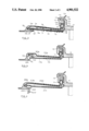
- FIG. 1 is a partial, longitudinal cross sectional view of an annular combustion chamber according to the invention.
- FIG. 2 is an enlarged cross-sectional view of the area indicated at A in FIG. 1.
- FIG. 3 is an enlarged, cross-sectional view of a second embodiment of the wall structure shown in FIG. 2.
- FIG. 4 is an enlarged, cross-sectional view of a third embodiment of the wall structure shown in FIG. 2.
- the combustion chamber 1 comprises a radially inner wall 2 defining the inner boundary of the combustion zone and the dilution zone, and a radially outer wall 3 defining the outer boundary of the combustion zone and the dilution zone.
- the inner and outer walls 2 and 3 are interconnected adjacent their upstream end portions by a base 4 in which the fuel injector mechanism and air inlets (not shown) are mounted in known fashion.
- the single thickness walls 2 and 3 define a primary combustion zone 5 in which the air-fuel mixture is ignited and burned, and a dilution zone 6 located downstream of the combustion zone 5 in which additional air is mixed with the combustion gases by passing through orifices formed in the inner and outer walls in known fashion.
- the interior surfaces of the inner and outer walls 2 are cooled by the presence of cooling air films, illustrated schematically at 8 and 9 in FIG. 1.
- the cooling air films 8 and 9 are generated from air supplied to annular chambers 10 and 11 which, in turn, are supplied by air through supply orifices 12 in known fashion.
- the combustion chamber 1 also includes a converging zone 7 that is defined by double thickness inner and outer walls.
- Each of the inner and outer walls comprises a cold wall 3a and a hot wall 13.
- the converging zone 7 converges in a downstream direction and is connected to the inlet of turbine section 16. Since the converging zone 7 subjects the encompassing walls high stresses generated by the pressure and the speed of the hot gases passing through this zone, both the inner and outer walls are made of double thickness.
- the cold wall 3a defines a generally axially facing notch 3b and a generally radially extending flange 3c extending from its downstream end portion.
- the flange 3c defines a plurality of bores 3d circumferentially displaced around the flange.
- a downstream portion of the cold wall 3a also defines a plurality of cooling perforations 3e.
- Each of the double thickness walls also comprises a hot wall 13 having a wall section 13a with an upstream portion 13b adapted to enter the notch 3b of the cold wall so as to support the upstream end of the hot wall therein.
- a generally radially extending flange 13c extends from the downstream end of the hot wall 13 so as to lie adjacent to the corresponding flange 3c.
- the flange 13c also defines of plurality of bores 13d which are circumferentially aligned with the bores 3d. Relative circumferential movement between the hot wall and the cold wall is prevented by the insertion of generally cylindrical studs 14 into the bores 3d and 13d, respectively.
- the hot wall 13a is radially displaced from the cold wall 3a so as to define a cooling space 17 therebetween.
- the upstream portion of hot wall 13a also defines a plurality of evacuation orifices 13f in order to evacuate the cooling air from the space 17.
- Such cooling air is supplied through the cooling perforations 3e and, as indicated by the arrows in FIG. 2, passes along the wall 13a in a direction contrary to the flow of the hot gases through the combustion chambers.
- the counter flow air is evacuated from the chamber 17 through evacuation orifices 13f.
- a lip 3f formed on the upstream portion of the cold wall 3 lies adjacent to the evacuation orifices 13f and directs the cooling air passing therethrough along the interior surface of the hot wall 13a to provide a cooling film thereon. This serves to prevent heat damage to the wall caused by the hot combustion gases.
- This cooling film may be supplemented by air passing through cooling perforations 13i formed in the downstream portion of the hot wall 13a.
- the cooling perforations 13i are positioned so as to be out of alignment with the cooling perforations 3e.
- the hot wall 13 may be formed from a plurality of arcuate segments 13a retained in position with respect to the cold wall by the interengagement of the upstream portion 13b in notch 3b and the cylindrical studs 14 engaging corresponding bores 3d and 13d.
- the downstream portions of the hot and cold walls are attached to the turbine section 16 via clamp 15.
- Clamp 15 has generally radially extending arms 15a defining a generally radially opening groove dimensioned so as to slidably receive the flanges 3c and 13c as illustrated in FIG. 2.
- the notch is dimensioned so as to prevent any substantial axial movement between the flanges and the clamp.
- the radial dimension of the notch is greater than that of the flanges 3c and 13c so as to permit relative radial movement therebetween caused by radial expansion or contraction of the walls due to the presence or absence of hot gases in the combustion chamber.
- Clamp 15 also has leg 15c defining a generally axially extending groove 15b dimensioned so as to slidably accept axially extending flange 16a or 16b (see FIG. 1) formed on the inlet of the turbine 16.
- the downstream end of leg 15c may be flared outwardly as at 15d to provide, along with the beveled surface 15e, a guide to the entrance of the flange 16a or 16b into the notch 15b.
- the structure of the double wall provides several means for cooling the hot wall and thereby preserving its useful life.
- the air passing through the perforations 3e serves to cool the wall by impact onto the wall 13a.
- Air passing into the space 17 between the hot and cold walls is guided in an upstream direction along one surface of the hot wall 17 by longitudinal guide strips 13e affixed to the surface of the hot wall 13 facing the cold wall 3.
- the longitudinal guide strips 13e extend in a generally longitudinal direction and cover substantially the entire height of the space 17 between the hot and cold walls.
- the air After passing along the surface of hot wall 13 the air passes through the evacuation openings 13f and, due to the presence of lip 3f, is guided along the interior surface of the wall 13a.
- This serves as a peripheral cooling film to convection cool the hot wall 13.
- This cooling film is supplemented by air passing through the cooling perforations 13i formed on the downstream half of the hot wall 13.
- the cooling perforations 13i are staggered and offset from the cooling perforations 3e to prevent the air passing directly through the space 17.
- FIG. 3 A second embodiment of the double thickness wall structure is illustrated in FIG. 3.
- the function of the generally radial flanges formed on the hot and cold walls, the clamping device and the cooling perforations all function as in the previously described embodiment.
- the only difference between this embodiment and that previously described resides in the attachment of the upstream end portion of the hot wall to that of the cold wall.
- each of the hot wall segments 113a defines an upstream facing lip 113j and the lip by which the hot wall 113a is attached to the cold wall 103a is displaced from the plane of the hot wall 113a.
- the cold wall 103a is shaped so as to define, with the lip 113j, a direction reversing chamber 118.
- the air passing into the chamber between the hot and cold walls through the cooling perforations 103e again passes in an upstream direction (toward the left as viewed in FIG. 3) through the evacuation orifices 113f and into the chamber 118.
- the lip 103f serves to direct this air emanating from chamber 118 along the surface of the hot wall 113a to form a cooling film. Again, this film may be supplemented by air passing through the cooling perforations 113i formed in the downstream half of the hot wall 113a.
- FIG. 4 A third embodiment of the double walled structure according to the invention is illustrated in FIG. 4 and differs from that shown in FIG. 2 only in the shape of the evacuation orifices indicated at 213f in FIG. 4.
- the evacuation orifices 213f are elongated and slanted relative to the longitudinal axis of the combustion chamber in order to achieve a better distribution of the cooling air over the lip 203f and to avoid any disturbances in the cooling film formed on the hot wall 213a.
- the structure according to the invention provides the converging nozzle portion of the combustion chamber with improved cooling of the walls, while at the same time simplifying the construction and the attachment to the turbine nozzle thereby decreasing the assembly time and maintenance costs.
Landscapes
- Engineering & Computer Science (AREA)
- Chemical & Material Sciences (AREA)
- Combustion & Propulsion (AREA)
- Mechanical Engineering (AREA)
- General Engineering & Computer Science (AREA)
- Turbine Rotor Nozzle Sealing (AREA)
Applications Claiming Priority (2)
| Application Number | Priority Date | Filing Date | Title |
|---|---|---|---|
| FR8717546 | 1987-12-16 | ||
| FR8717546A FR2624953B1 (fr) | 1987-12-16 | 1987-12-16 | Chambre de combustion, pour turbomachines, possedant un convergent a doubles parois |
Publications (1)
| Publication Number | Publication Date |
|---|---|
| US4901522A true US4901522A (en) | 1990-02-20 |
Family
ID=9357918
Family Applications (1)
| Application Number | Title | Priority Date | Filing Date |
|---|---|---|---|
| US07/281,749 Expired - Lifetime US4901522A (en) | 1987-12-16 | 1988-12-09 | Turbojet engine combustion chamber with a double wall converging zone |
Country Status (4)
| Country | Link |
|---|---|
| US (1) | US4901522A (de) |
| EP (1) | EP0321320B1 (de) |
| DE (1) | DE3861318D1 (de) |
| FR (1) | FR2624953B1 (de) |
Cited By (67)
| Publication number | Priority date | Publication date | Assignee | Title |
|---|---|---|---|---|
| US5265412A (en) * | 1992-07-28 | 1993-11-30 | General Electric Company | Self-accommodating brush seal for gas turbine combustor |
| US5291732A (en) * | 1993-02-08 | 1994-03-08 | General Electric Company | Combustor liner support assembly |
| DE4239856A1 (de) * | 1992-11-27 | 1994-06-01 | Asea Brown Boveri | Gasturbinenbrennkammer |
| US5323601A (en) * | 1992-12-21 | 1994-06-28 | United Technologies Corporation | Individually removable combustor liner panel for a gas turbine engine |
| US5333443A (en) * | 1993-02-08 | 1994-08-02 | General Electric Company | Seal assembly |
| US5363654A (en) * | 1993-05-10 | 1994-11-15 | General Electric Company | Recuperative impingement cooling of jet engine components |
| US5400586A (en) * | 1992-07-28 | 1995-03-28 | General Electric Co. | Self-accommodating brush seal for gas turbine combustor |
| US5419170A (en) * | 1993-10-15 | 1995-05-30 | The Boeing Company | Gas control for superplastic forming |
| US5435139A (en) * | 1991-03-22 | 1995-07-25 | Rolls-Royce Plc | Removable combustor liner for gas turbine engine combustor |
| US5474306A (en) * | 1992-11-19 | 1995-12-12 | General Electric Co. | Woven seal and hybrid cloth-brush seals for turbine applications |
| EP0718468A1 (de) * | 1994-12-20 | 1996-06-26 | General Electric Company | Verstärkungrahmen für Gasturbinenbrennkammerendstück |
| US5560198A (en) * | 1995-05-25 | 1996-10-01 | United Technologies Corporation | Cooled gas turbine engine augmentor fingerseal assembly |
| US5598697A (en) * | 1994-07-27 | 1997-02-04 | Societe Nationale D'etude Et De Construction De Moteurs D'aviation S.N.E.C.M.A. | Double wall construction for a gas turbine combustion chamber |
| US5749584A (en) * | 1992-11-19 | 1998-05-12 | General Electric Company | Combined brush seal and labyrinth seal segment for rotary machines |
| WO1999063274A1 (en) * | 1998-06-03 | 1999-12-09 | Pratt & Whitney Canada Corp. | Impingement and film cooling for gas turbine combustor walls |
| US6027121A (en) * | 1997-10-23 | 2000-02-22 | General Electric Co. | Combined brush/labyrinth seal for rotary machines |
| US6045134A (en) * | 1998-02-04 | 2000-04-04 | General Electric Co. | Combined labyrinth and brush seals for rotary machines |
| EP0896193A3 (de) * | 1997-08-05 | 2000-07-26 | European Gas Turbines Limited | Gasturbinenbrennkammer |
| US6131910A (en) * | 1992-11-19 | 2000-10-17 | General Electric Co. | Brush seals and combined labyrinth and brush seals for rotary machines |
| US6139018A (en) * | 1998-03-25 | 2000-10-31 | General Electric Co. | Positive pressure-actuated brush seal |
| RU2159347C1 (ru) * | 1999-02-23 | 2000-11-20 | Открытое акционерное общество "Авиадвигатель" | Газотурбинный двигатель |
| US6168162B1 (en) | 1998-08-05 | 2001-01-02 | General Electric Co. | Self-centering brush seal |
| US6250640B1 (en) | 1998-08-17 | 2001-06-26 | General Electric Co. | Brush seals for steam turbine applications |
| US6290232B1 (en) | 1999-11-16 | 2001-09-18 | General Electric Co. | Rub-tolerant brush seal for turbine rotors and methods of installation |
| JP2001317739A (ja) * | 2000-05-05 | 2001-11-16 | General Electric Co <Ge> | セラミック母材複合材料製のライナを有する燃焼器 |
| US6331006B1 (en) | 2000-01-25 | 2001-12-18 | General Electric Company | Brush seal mounting in supporting groove using flat spring with bifurcated end |
| WO2002002911A1 (en) * | 2000-07-03 | 2002-01-10 | Nuovo Pignone Holding S.P.A. | Connecting system for a transition duct in a gas turbine |
| US6408628B1 (en) * | 1999-11-06 | 2002-06-25 | Rolls-Royce Plc | Wall elements for gas turbine engine combustors |
| EP1035377A3 (de) * | 1999-03-08 | 2002-08-21 | Mitsubishi Heavy Industries, Ltd. | Abdichtung für das Endstück einer Gasturbinenbrennkammer |
| RU2223447C2 (ru) * | 2001-12-06 | 2004-02-10 | Межрегиональная общественная организация "Поволжское отделение Российской инженерной академии" | Устройство для крепления жаровой трубы в корпусе камеры сгорания |
| RU2223448C2 (ru) * | 2001-12-06 | 2004-02-10 | Межрегиональная общественная организация "Поволжское отделение Российской инженерной академии" | Устройство для крепления жаровой трубы в корпусе камеры сгорания |
| US20040250549A1 (en) * | 2001-11-15 | 2004-12-16 | Roland Liebe | Annular combustion chamber for a gas turbine |
| US20050086940A1 (en) * | 2003-10-23 | 2005-04-28 | Coughlan Joseph D.Iii | Combustor |
| RU2287115C1 (ru) * | 2005-04-15 | 2006-11-10 | Федеральное государственное унитарное предприятие "Московское машиностроительное производственное предприятие "САЛЮТ" (ФГУП "ММПП "САЛЮТ") | Кольцевая камера сгорания газотурбинного двигателя |
| WO2006120204A1 (de) * | 2005-05-13 | 2006-11-16 | Siemens Aktiengesellschaft | Brennkammerwand, gasturbinenanlage und verfahren zum an- oder abfahren einer gasturbinenanlage |
| US20070144177A1 (en) * | 2005-12-22 | 2007-06-28 | Burd Steven W | Combustor turbine interface |
| US20080148738A1 (en) * | 2006-12-21 | 2008-06-26 | Pratt & Whitney Canada Corp. | Combustor construction |
| US20090047127A1 (en) * | 2007-08-13 | 2009-02-19 | Snecma | turbomachine diffuser |
| US20090120096A1 (en) * | 2007-11-09 | 2009-05-14 | United Technologies Corp. | Gas Turbine Engine Systems Involving Cooling of Combustion Section Liners |
| US20100095678A1 (en) * | 2008-10-22 | 2010-04-22 | Eduardo Hawie | Heat Shield Sealing for Gas Turbine Engine Combustor |
| US20110179804A1 (en) * | 2009-03-05 | 2011-07-28 | Eric Andrew Nager | Radial turbine engine floating ring seal |
| US20120167571A1 (en) * | 2011-01-03 | 2012-07-05 | David William Cihlar | Combustor assemblies for use in turbine engines and methods of assembling same |
| US20120260659A1 (en) * | 2011-04-18 | 2012-10-18 | Foust Adam M | Interface between a combustor basket and a transition of a gas turbine engine |
| US20140223921A1 (en) * | 2011-10-24 | 2014-08-14 | Alstom Technology Ltd | Gas turbine |
| US20140360196A1 (en) * | 2013-03-15 | 2014-12-11 | Rolls-Royce Corporation | Shell and tiled liner arrangement for a combustor |
| WO2015077755A1 (en) * | 2013-11-25 | 2015-05-28 | United Technologies Corporation | Film cooled multi-walled structure with one or more indentations |
| WO2015077600A1 (en) | 2013-11-21 | 2015-05-28 | United Technologies Corporation | Cooling a multi-walled structure of a turbine engine |
| EP2778532A4 (de) * | 2011-11-10 | 2015-07-08 | Ihi Corp | Brennkammerwand |
| US20150300645A1 (en) * | 2013-09-06 | 2015-10-22 | Rolls-Royce Plc | Combustion chamber arrangement |
| US20160238249A1 (en) * | 2013-10-18 | 2016-08-18 | United Technologies Corporation | Combustor wall having cooling element(s) within a cooling cavity |
| US20160258623A1 (en) * | 2015-03-05 | 2016-09-08 | United Technologies Corporation | Combustor and heat shield configurations for a gas turbine engine |
| US20170108219A1 (en) * | 2015-10-16 | 2017-04-20 | Rolls-Royce Plc | Combustor for a gas turbine engine |
| EP1555393B1 (de) | 2004-01-14 | 2017-07-19 | General Electric Company | Gasturbinenmotorbauteil mit einem Bypasskreislauf |
| EP2325563A3 (de) * | 2009-11-23 | 2018-01-10 | Honeywell International Inc. | Doppelwandige Flammrohre mit verbesserten Verkleidungsabdichtungen |
| US20180299126A1 (en) * | 2017-04-18 | 2018-10-18 | United Technologies Corporation | Combustor liner panel end rail |
| GB2569449A (en) * | 2017-12-05 | 2019-06-19 | Rolls Royce Plc | A combustion chamber arrangement |
| US10344977B2 (en) * | 2016-02-24 | 2019-07-09 | Rolls-Royce Plc | Combustion chamber having an annular outer wall with a concave bend |
| US10634350B2 (en) | 2015-08-13 | 2020-04-28 | Rolls-Royce Plc | Combustion chamber and a combustion chamber segment |
| US11371701B1 (en) | 2021-02-03 | 2022-06-28 | General Electric Company | Combustor for a gas turbine engine |
| US11402100B2 (en) * | 2018-11-15 | 2022-08-02 | Pratt & Whitney Canada Corp. | Ring assembly for double-skin combustor liner |
| US11774098B2 (en) | 2021-06-07 | 2023-10-03 | General Electric Company | Combustor for a gas turbine engine |
| US11885495B2 (en) | 2021-06-07 | 2024-01-30 | General Electric Company | Combustor for a gas turbine engine including a liner having a looped feature |
| US11959643B2 (en) | 2021-06-07 | 2024-04-16 | General Electric Company | Combustor for a gas turbine engine |
| US12085283B2 (en) | 2021-06-07 | 2024-09-10 | General Electric Company | Combustor for a gas turbine engine |
| US12146660B2 (en) | 2021-06-07 | 2024-11-19 | General Electric Company | Combustor for a gas turbine engine |
| US12152777B2 (en) | 2021-06-07 | 2024-11-26 | General Electric Company | Combustor for a gas turbine engine |
| US12326255B2 (en) | 2022-08-12 | 2025-06-10 | General Electric Company | Dome-deflector for a combustor of a gas turbine |
Families Citing this family (5)
| Publication number | Priority date | Publication date | Assignee | Title |
|---|---|---|---|---|
| US5461866A (en) * | 1994-12-15 | 1995-10-31 | United Technologies Corporation | Gas turbine engine combustion liner float wall cooling arrangement |
| DE19727407A1 (de) * | 1997-06-27 | 1999-01-07 | Siemens Ag | Hitzeschild |
| US8869538B2 (en) * | 2010-12-24 | 2014-10-28 | Rolls-Royce North American Technologies, Inc. | Gas turbine engine flow path member |
| FR2982660B1 (fr) * | 2011-11-14 | 2014-01-10 | Snecma | Carenage de chambre de combustion de turbomachine comprenant des reseaux de percages |
| FR3004518B1 (fr) * | 2013-04-11 | 2017-12-08 | Snecma | Chambre de combustion annulaire d'une turbomachine |
Citations (13)
| Publication number | Priority date | Publication date | Assignee | Title |
|---|---|---|---|---|
| US2813297A (en) * | 1955-10-27 | 1957-11-19 | Dahlin Ell | Fish and game vise |
| DE1957147A1 (de) * | 1968-11-15 | 1970-06-04 | Rolls Royce | Flammrohr fuer Verbrennungsanlagen von Gasturbinentriebwerken |
| US4232527A (en) * | 1979-04-13 | 1980-11-11 | General Motors Corporation | Combustor liner joints |
| US4480436A (en) * | 1972-12-19 | 1984-11-06 | General Electric Company | Combustion chamber construction |
| US4555901A (en) * | 1972-12-19 | 1985-12-03 | General Electric Company | Combustion chamber construction |
| FR2567250A1 (fr) * | 1984-07-06 | 1986-01-10 | Gen Electric | Chambre de combustion pour moteur a turbine a gaz |
| US4567730A (en) * | 1983-10-03 | 1986-02-04 | General Electric Company | Shielded combustor |
| GB2172987A (en) * | 1972-12-19 | 1986-10-01 | Gen Electric | Combustion chamber construction |
| US4628694A (en) * | 1983-12-19 | 1986-12-16 | General Electric Company | Fabricated liner article and method |
| US4688310A (en) * | 1983-12-19 | 1987-08-25 | General Electric Company | Fabricated liner article and method |
| EP0248731A1 (de) * | 1986-06-04 | 1987-12-09 | Societe Nationale D'etude Et De Construction De Moteurs D'aviation, "S.N.E.C.M.A." | Gasturbinenbrennkammer mit Mischöffnungen, die eine heisse Wand gegenüber einer kühlen Wand Festlegen |
| US4719748A (en) * | 1985-05-14 | 1988-01-19 | General Electric Company | Impingement cooled transition duct |
| GB2200738A (en) * | 1987-02-06 | 1988-08-10 | Gen Electric | Combustor liner cooling arrangement |
Family Cites Families (1)
| Publication number | Priority date | Publication date | Assignee | Title |
|---|---|---|---|---|
| US2813397A (en) * | 1957-01-02 | 1957-11-19 | United Aircraft Corp | Thermal expansion means for combustion chambers |
-
1987
- 1987-12-16 FR FR8717546A patent/FR2624953B1/fr not_active Expired - Lifetime
-
1988
- 1988-11-23 DE DE8888402927T patent/DE3861318D1/de not_active Expired - Lifetime
- 1988-11-23 EP EP88402927A patent/EP0321320B1/de not_active Expired - Lifetime
- 1988-12-09 US US07/281,749 patent/US4901522A/en not_active Expired - Lifetime
Patent Citations (16)
| Publication number | Priority date | Publication date | Assignee | Title |
|---|---|---|---|---|
| US2813297A (en) * | 1955-10-27 | 1957-11-19 | Dahlin Ell | Fish and game vise |
| DE1957147A1 (de) * | 1968-11-15 | 1970-06-04 | Rolls Royce | Flammrohr fuer Verbrennungsanlagen von Gasturbinentriebwerken |
| US3899876A (en) * | 1968-11-15 | 1975-08-19 | Secr Defence Brit | Flame tube for a gas turbine combustion equipment |
| GB2172987A (en) * | 1972-12-19 | 1986-10-01 | Gen Electric | Combustion chamber construction |
| US4480436A (en) * | 1972-12-19 | 1984-11-06 | General Electric Company | Combustion chamber construction |
| US4555901A (en) * | 1972-12-19 | 1985-12-03 | General Electric Company | Combustion chamber construction |
| FR2579724A1 (fr) * | 1972-12-19 | 1986-10-03 | Gen Electric | Construction de chambre de combustion pour un moteur a turbine a gaz |
| US4232527A (en) * | 1979-04-13 | 1980-11-11 | General Motors Corporation | Combustor liner joints |
| US4567730A (en) * | 1983-10-03 | 1986-02-04 | General Electric Company | Shielded combustor |
| US4628694A (en) * | 1983-12-19 | 1986-12-16 | General Electric Company | Fabricated liner article and method |
| US4688310A (en) * | 1983-12-19 | 1987-08-25 | General Electric Company | Fabricated liner article and method |
| FR2567250A1 (fr) * | 1984-07-06 | 1986-01-10 | Gen Electric | Chambre de combustion pour moteur a turbine a gaz |
| US4719748A (en) * | 1985-05-14 | 1988-01-19 | General Electric Company | Impingement cooled transition duct |
| EP0248731A1 (de) * | 1986-06-04 | 1987-12-09 | Societe Nationale D'etude Et De Construction De Moteurs D'aviation, "S.N.E.C.M.A." | Gasturbinenbrennkammer mit Mischöffnungen, die eine heisse Wand gegenüber einer kühlen Wand Festlegen |
| US4805397A (en) * | 1986-06-04 | 1989-02-21 | Societe Nationale D'etude Et De Construction De Moteurs D'aviation (Snecma) | Combustion chamber structure for a turbojet engine |
| GB2200738A (en) * | 1987-02-06 | 1988-08-10 | Gen Electric | Combustor liner cooling arrangement |
Cited By (117)
| Publication number | Priority date | Publication date | Assignee | Title |
|---|---|---|---|---|
| US5435139A (en) * | 1991-03-22 | 1995-07-25 | Rolls-Royce Plc | Removable combustor liner for gas turbine engine combustor |
| US5400586A (en) * | 1992-07-28 | 1995-03-28 | General Electric Co. | Self-accommodating brush seal for gas turbine combustor |
| US5265412A (en) * | 1992-07-28 | 1993-11-30 | General Electric Company | Self-accommodating brush seal for gas turbine combustor |
| US5749584A (en) * | 1992-11-19 | 1998-05-12 | General Electric Company | Combined brush seal and labyrinth seal segment for rotary machines |
| US6173958B1 (en) | 1992-11-19 | 2001-01-16 | General Electric Co. | Hybrid labyrinth and cloth-brush seals for turbine applications |
| US6010132A (en) * | 1992-11-19 | 2000-01-04 | General Electric Co. | Hybrid labyrinth and cloth-brush seals for turbine applications |
| US6435513B2 (en) | 1992-11-19 | 2002-08-20 | General Electric Company | Combined brush seal and labyrinth seal segment for rotary machines |
| US6042119A (en) * | 1992-11-19 | 2000-03-28 | General Electric Co. | Woven seals and hybrid cloth-brush seals for turbine applications |
| US6131910A (en) * | 1992-11-19 | 2000-10-17 | General Electric Co. | Brush seals and combined labyrinth and brush seals for rotary machines |
| US6257586B1 (en) | 1992-11-19 | 2001-07-10 | General Electric Co. | Combined brush seal and labyrinth seal segment for rotary machines |
| US5474306A (en) * | 1992-11-19 | 1995-12-12 | General Electric Co. | Woven seal and hybrid cloth-brush seals for turbine applications |
| JP3414806B2 (ja) | 1992-11-27 | 2003-06-09 | アルストム | ガスタービンの燃焼器 |
| DE4239856A1 (de) * | 1992-11-27 | 1994-06-01 | Asea Brown Boveri | Gasturbinenbrennkammer |
| US5388412A (en) * | 1992-11-27 | 1995-02-14 | Asea Brown Boveri Ltd. | Gas turbine combustion chamber with impingement cooling tubes |
| US5323601A (en) * | 1992-12-21 | 1994-06-28 | United Technologies Corporation | Individually removable combustor liner panel for a gas turbine engine |
| US5291732A (en) * | 1993-02-08 | 1994-03-08 | General Electric Company | Combustor liner support assembly |
| US5333443A (en) * | 1993-02-08 | 1994-08-02 | General Electric Company | Seal assembly |
| US5363654A (en) * | 1993-05-10 | 1994-11-15 | General Electric Company | Recuperative impingement cooling of jet engine components |
| US5419170A (en) * | 1993-10-15 | 1995-05-30 | The Boeing Company | Gas control for superplastic forming |
| US5598697A (en) * | 1994-07-27 | 1997-02-04 | Societe Nationale D'etude Et De Construction De Moteurs D'aviation S.N.E.C.M.A. | Double wall construction for a gas turbine combustion chamber |
| US5761898A (en) * | 1994-12-20 | 1998-06-09 | General Electric Co. | Transition piece external frame support |
| EP0718468A1 (de) * | 1994-12-20 | 1996-06-26 | General Electric Company | Verstärkungrahmen für Gasturbinenbrennkammerendstück |
| US5560198A (en) * | 1995-05-25 | 1996-10-01 | United Technologies Corporation | Cooled gas turbine engine augmentor fingerseal assembly |
| EP0896193A3 (de) * | 1997-08-05 | 2000-07-26 | European Gas Turbines Limited | Gasturbinenbrennkammer |
| US6027121A (en) * | 1997-10-23 | 2000-02-22 | General Electric Co. | Combined brush/labyrinth seal for rotary machines |
| US6105967A (en) * | 1998-02-04 | 2000-08-22 | General Electric Co. | Combined labyrinth and brush seals for rotary machines |
| US6045134A (en) * | 1998-02-04 | 2000-04-04 | General Electric Co. | Combined labyrinth and brush seals for rotary machines |
| US6139018A (en) * | 1998-03-25 | 2000-10-31 | General Electric Co. | Positive pressure-actuated brush seal |
| US6079199A (en) * | 1998-06-03 | 2000-06-27 | Pratt & Whitney Canada Inc. | Double pass air impingement and air film cooling for gas turbine combustor walls |
| WO1999063274A1 (en) * | 1998-06-03 | 1999-12-09 | Pratt & Whitney Canada Corp. | Impingement and film cooling for gas turbine combustor walls |
| US6168162B1 (en) | 1998-08-05 | 2001-01-02 | General Electric Co. | Self-centering brush seal |
| US6250640B1 (en) | 1998-08-17 | 2001-06-26 | General Electric Co. | Brush seals for steam turbine applications |
| RU2159347C1 (ru) * | 1999-02-23 | 2000-11-20 | Открытое акционерное общество "Авиадвигатель" | Газотурбинный двигатель |
| US6751962B1 (en) | 1999-03-08 | 2004-06-22 | Mitsubishi Heavy Industries, Ltd. | Tail tube seal structure of combustor and a gas turbine using the same structure |
| EP1035377A3 (de) * | 1999-03-08 | 2002-08-21 | Mitsubishi Heavy Industries, Ltd. | Abdichtung für das Endstück einer Gasturbinenbrennkammer |
| US6408628B1 (en) * | 1999-11-06 | 2002-06-25 | Rolls-Royce Plc | Wall elements for gas turbine engine combustors |
| US6290232B1 (en) | 1999-11-16 | 2001-09-18 | General Electric Co. | Rub-tolerant brush seal for turbine rotors and methods of installation |
| US6331006B1 (en) | 2000-01-25 | 2001-12-18 | General Electric Company | Brush seal mounting in supporting groove using flat spring with bifurcated end |
| JP2001317739A (ja) * | 2000-05-05 | 2001-11-16 | General Electric Co <Ge> | セラミック母材複合材料製のライナを有する燃焼器 |
| US6893209B2 (en) | 2000-07-03 | 2005-05-17 | Nuovo Pignone Holding S.P.A. | Connecting system for a transition duct in a gas turbine |
| JP2004502081A (ja) * | 2000-07-03 | 2004-01-22 | ヌオーヴォ ピニォーネ ホールディング ソシエタ ペル アチオニ | ガスタービンの移行ダクト用の連結装置 |
| KR100814174B1 (ko) | 2000-07-03 | 2008-03-14 | 누보 피그노네 홀딩 에스피에이 | 가스 터빈에서 트랜지션 덕트를 저압 제트에 연결하는시스템 및 저압 제트 |
| US20040037699A1 (en) * | 2000-07-03 | 2004-02-26 | Franco Frosini | Connecting system for a transition duct in a gas turbine |
| WO2002002911A1 (en) * | 2000-07-03 | 2002-01-10 | Nuovo Pignone Holding S.P.A. | Connecting system for a transition duct in a gas turbine |
| JP4753526B2 (ja) * | 2000-07-03 | 2011-08-24 | ヌオーヴォ ピニォーネ ホールディング ソシエタ ペル アチオニ | ガスタービンの移行ダクト用の連結装置 |
| US20040250549A1 (en) * | 2001-11-15 | 2004-12-16 | Roland Liebe | Annular combustion chamber for a gas turbine |
| RU2223448C2 (ru) * | 2001-12-06 | 2004-02-10 | Межрегиональная общественная организация "Поволжское отделение Российской инженерной академии" | Устройство для крепления жаровой трубы в корпусе камеры сгорания |
| RU2223447C2 (ru) * | 2001-12-06 | 2004-02-10 | Межрегиональная общественная организация "Поволжское отделение Российской инженерной академии" | Устройство для крепления жаровой трубы в корпусе камеры сгорания |
| EP1528322A3 (de) * | 2003-10-23 | 2005-06-08 | United Technologies Corporation | Brennkammer |
| US8015829B2 (en) | 2003-10-23 | 2011-09-13 | United Technologies Corporation | Combustor |
| US20050086940A1 (en) * | 2003-10-23 | 2005-04-28 | Coughlan Joseph D.Iii | Combustor |
| US7363763B2 (en) | 2003-10-23 | 2008-04-29 | United Technologies Corporation | Combustor |
| US20090293488A1 (en) * | 2003-10-23 | 2009-12-03 | United Technologies Corporation | Combustor |
| EP2034244A1 (de) * | 2003-10-23 | 2009-03-11 | United Technologies Corporation | Verbrennungsanlage |
| EP1555393B1 (de) | 2004-01-14 | 2017-07-19 | General Electric Company | Gasturbinenmotorbauteil mit einem Bypasskreislauf |
| RU2287115C1 (ru) * | 2005-04-15 | 2006-11-10 | Федеральное государственное унитарное предприятие "Московское машиностроительное производственное предприятие "САЛЮТ" (ФГУП "ММПП "САЛЮТ") | Кольцевая камера сгорания газотурбинного двигателя |
| US20090094986A1 (en) * | 2005-05-13 | 2009-04-16 | Andreas Bottcher | Combustion Chamber Wall, Gas Turbine Installation and Process for Starting or Shutting Down a Gas Turbine Installation |
| EP1724526A1 (de) * | 2005-05-13 | 2006-11-22 | Siemens Aktiengesellschaft | Brennkammerschale, Gasturbinenanlage und Verfahren zum An- oder Abfahren einer Gasturbinenanlage |
| US8091364B2 (en) | 2005-05-13 | 2012-01-10 | Siemens Aktiengesellschaft | Combustion chamber wall, gas turbine installation and process for starting or shutting down a gas turbine installation |
| WO2006120204A1 (de) * | 2005-05-13 | 2006-11-16 | Siemens Aktiengesellschaft | Brennkammerwand, gasturbinenanlage und verfahren zum an- oder abfahren einer gasturbinenanlage |
| US7934382B2 (en) * | 2005-12-22 | 2011-05-03 | United Technologies Corporation | Combustor turbine interface |
| US20070144177A1 (en) * | 2005-12-22 | 2007-06-28 | Burd Steven W | Combustor turbine interface |
| US8794005B2 (en) * | 2006-12-21 | 2014-08-05 | Pratt & Whitney Canada Corp. | Combustor construction |
| US20080148738A1 (en) * | 2006-12-21 | 2008-06-26 | Pratt & Whitney Canada Corp. | Combustor construction |
| US8047777B2 (en) | 2007-08-13 | 2011-11-01 | Snecma | Turbomachine diffuser |
| US20090047127A1 (en) * | 2007-08-13 | 2009-02-19 | Snecma | turbomachine diffuser |
| US8051663B2 (en) | 2007-11-09 | 2011-11-08 | United Technologies Corp. | Gas turbine engine systems involving cooling of combustion section liners |
| US8307656B2 (en) | 2007-11-09 | 2012-11-13 | United Technologies Corp. | Gas turbine engine systems involving cooling of combustion section liners |
| US20090120096A1 (en) * | 2007-11-09 | 2009-05-14 | United Technologies Corp. | Gas Turbine Engine Systems Involving Cooling of Combustion Section Liners |
| US20100095678A1 (en) * | 2008-10-22 | 2010-04-22 | Eduardo Hawie | Heat Shield Sealing for Gas Turbine Engine Combustor |
| US8266914B2 (en) | 2008-10-22 | 2012-09-18 | Pratt & Whitney Canada Corp. | Heat shield sealing for gas turbine engine combustor |
| US20110179804A1 (en) * | 2009-03-05 | 2011-07-28 | Eric Andrew Nager | Radial turbine engine floating ring seal |
| US8474267B2 (en) * | 2009-03-05 | 2013-07-02 | Hamilton Sundstrand Corporation | Radial turbine engine floating ring seal |
| EP2325563A3 (de) * | 2009-11-23 | 2018-01-10 | Honeywell International Inc. | Doppelwandige Flammrohre mit verbesserten Verkleidungsabdichtungen |
| US20120167571A1 (en) * | 2011-01-03 | 2012-07-05 | David William Cihlar | Combustor assemblies for use in turbine engines and methods of assembling same |
| US8813501B2 (en) * | 2011-01-03 | 2014-08-26 | General Electric Company | Combustor assemblies for use in turbine engines and methods of assembling same |
| US8973376B2 (en) * | 2011-04-18 | 2015-03-10 | Siemens Aktiengesellschaft | Interface between a combustor basket and a transition of a gas turbine engine |
| US20120260659A1 (en) * | 2011-04-18 | 2012-10-18 | Foust Adam M | Interface between a combustor basket and a transition of a gas turbine engine |
| US20140223921A1 (en) * | 2011-10-24 | 2014-08-14 | Alstom Technology Ltd | Gas turbine |
| US9708920B2 (en) * | 2011-10-24 | 2017-07-18 | General Electric Technology Gmbh | Gas turbine support element permitting thermal expansion between combustor shell and rotor cover at turbine inlet |
| EP2778532A4 (de) * | 2011-11-10 | 2015-07-08 | Ihi Corp | Brennkammerwand |
| US10551067B2 (en) | 2011-11-10 | 2020-02-04 | Ihi Corporation | Combustor liner with dual wall cooling structure |
| US9423129B2 (en) * | 2013-03-15 | 2016-08-23 | Rolls-Royce Corporation | Shell and tiled liner arrangement for a combustor |
| US10458652B2 (en) | 2013-03-15 | 2019-10-29 | Rolls-Royce Corporation | Shell and tiled liner arrangement for a combustor |
| US20140360196A1 (en) * | 2013-03-15 | 2014-12-11 | Rolls-Royce Corporation | Shell and tiled liner arrangement for a combustor |
| US9651258B2 (en) | 2013-03-15 | 2017-05-16 | Rolls-Royce Corporation | Shell and tiled liner arrangement for a combustor |
| US11274829B2 (en) | 2013-03-15 | 2022-03-15 | Rolls-Royce Corporation | Shell and tiled liner arrangement for a combustor |
| US20150300645A1 (en) * | 2013-09-06 | 2015-10-22 | Rolls-Royce Plc | Combustion chamber arrangement |
| US9835332B2 (en) * | 2013-09-06 | 2017-12-05 | Rolls-Royce Plc | Combustion chamber arrangement |
| US20160238249A1 (en) * | 2013-10-18 | 2016-08-18 | United Technologies Corporation | Combustor wall having cooling element(s) within a cooling cavity |
| EP3071816A4 (de) * | 2013-11-21 | 2017-01-18 | United Technologies Corporation | Kühlung einer mehrwandigen struktur eines turbinenmotors |
| US20160273772A1 (en) * | 2013-11-21 | 2016-09-22 | United Technologies Corporation | Cooling a multi-walled structure of a turbine engine |
| US10317078B2 (en) | 2013-11-21 | 2019-06-11 | United Technologies Corporation | Cooling a multi-walled structure of a turbine engine |
| WO2015077600A1 (en) | 2013-11-21 | 2015-05-28 | United Technologies Corporation | Cooling a multi-walled structure of a turbine engine |
| WO2015077755A1 (en) * | 2013-11-25 | 2015-05-28 | United Technologies Corporation | Film cooled multi-walled structure with one or more indentations |
| US10598379B2 (en) | 2013-11-25 | 2020-03-24 | United Technologies Corporation | Film cooled multi-walled structure with one or more indentations |
| US20160258623A1 (en) * | 2015-03-05 | 2016-09-08 | United Technologies Corporation | Combustor and heat shield configurations for a gas turbine engine |
| US10634350B2 (en) | 2015-08-13 | 2020-04-28 | Rolls-Royce Plc | Combustion chamber and a combustion chamber segment |
| US20170108219A1 (en) * | 2015-10-16 | 2017-04-20 | Rolls-Royce Plc | Combustor for a gas turbine engine |
| US10408452B2 (en) * | 2015-10-16 | 2019-09-10 | Rolls-Royce Plc | Array of effusion holes in a dual wall combustor |
| US10344977B2 (en) * | 2016-02-24 | 2019-07-09 | Rolls-Royce Plc | Combustion chamber having an annular outer wall with a concave bend |
| US20180299126A1 (en) * | 2017-04-18 | 2018-10-18 | United Technologies Corporation | Combustor liner panel end rail |
| GB2569449B (en) * | 2017-12-05 | 2021-06-23 | Rolls Royce Plc | A gas turbine engine combustion chamber arrangement |
| US10907830B2 (en) | 2017-12-05 | 2021-02-02 | Rolls-Royce Plc | Combustor chamber arrangement with sealing ring |
| GB2569449A (en) * | 2017-12-05 | 2019-06-19 | Rolls Royce Plc | A combustion chamber arrangement |
| US11402100B2 (en) * | 2018-11-15 | 2022-08-02 | Pratt & Whitney Canada Corp. | Ring assembly for double-skin combustor liner |
| US11371701B1 (en) | 2021-02-03 | 2022-06-28 | General Electric Company | Combustor for a gas turbine engine |
| US11549686B2 (en) | 2021-02-03 | 2023-01-10 | General Electric Company | Combustor for a gas turbine engine |
| US11885495B2 (en) | 2021-06-07 | 2024-01-30 | General Electric Company | Combustor for a gas turbine engine including a liner having a looped feature |
| US11774098B2 (en) | 2021-06-07 | 2023-10-03 | General Electric Company | Combustor for a gas turbine engine |
| US11959643B2 (en) | 2021-06-07 | 2024-04-16 | General Electric Company | Combustor for a gas turbine engine |
| US12085283B2 (en) | 2021-06-07 | 2024-09-10 | General Electric Company | Combustor for a gas turbine engine |
| US12146660B2 (en) | 2021-06-07 | 2024-11-19 | General Electric Company | Combustor for a gas turbine engine |
| US12152777B2 (en) | 2021-06-07 | 2024-11-26 | General Electric Company | Combustor for a gas turbine engine |
| US12492821B2 (en) | 2021-06-07 | 2025-12-09 | General Electric Company | Combustor for a gas turbine engine |
| US12578095B2 (en) | 2021-06-07 | 2026-03-17 | General Electric Company | Combustor for a gas turbine engine |
| US12326255B2 (en) | 2022-08-12 | 2025-06-10 | General Electric Company | Dome-deflector for a combustor of a gas turbine |
Also Published As
| Publication number | Publication date |
|---|---|
| EP0321320B1 (de) | 1990-12-19 |
| FR2624953A1 (fr) | 1989-06-23 |
| DE3861318D1 (de) | 1991-01-31 |
| EP0321320A1 (de) | 1989-06-21 |
| FR2624953B1 (fr) | 1990-04-20 |
Similar Documents
| Publication | Publication Date | Title |
|---|---|---|
| US4901522A (en) | Turbojet engine combustion chamber with a double wall converging zone | |
| US4805397A (en) | Combustion chamber structure for a turbojet engine | |
| US5253471A (en) | Gas turbine engine combustor | |
| US6408629B1 (en) | Combustor liner having preferentially angled cooling holes | |
| US4414816A (en) | Combustor liner construction | |
| US4297843A (en) | Combustor of gas turbine with features for vibration reduction and increased cooling | |
| US4109459A (en) | Double walled impingement cooled combustor | |
| US5396759A (en) | Gas turbine engine combustor | |
| US7010921B2 (en) | Method and apparatus for cooling combustor liner and transition piece of a gas turbine | |
| US3793827A (en) | Stiffener for combustor liner | |
| US3995422A (en) | Combustor liner structure | |
| US6205789B1 (en) | Multi-hole film cooled combuster liner | |
| US6029455A (en) | Turbojet engine combustion chamber with heat protecting lining | |
| US4104874A (en) | Double-walled combustion chamber shell having combined convective wall cooling and film cooling | |
| US3712062A (en) | Cooled augmentor liner | |
| US8544277B2 (en) | Turbulated aft-end liner assembly and cooling method | |
| US5012645A (en) | Combustor liner construction for gas turbine engine | |
| US6253540B1 (en) | Removable baffle infrared suppressor | |
| US10197285B2 (en) | Gas turbine engine wall assembly interface | |
| JPS6335897B2 (de) | ||
| JPS5920861B2 (ja) | 冷却用ライナの取付け及び安定化装置 | |
| JPH02267352A (ja) | ターボジェットエンジンの高温流路の熱遮蔽ジャケット | |
| US10739001B2 (en) | Combustor liner panel shell interface for a gas turbine engine combustor | |
| US20110239654A1 (en) | Angled seal cooling system | |
| US5001896A (en) | Impingement cooled crossfire tube assembly in multiple-combustor gas turbine engine |
Legal Events
| Date | Code | Title | Description |
|---|---|---|---|
| AS | Assignment |
Owner name: SOCIETE NATIONALE D'ETUDE ET DE CONSTRUCTIONS DE M Free format text: ASSIGNMENT OF ASSIGNORS INTEREST.;ASSIGNORS:COMMARET, PATRICE;DESAULTY, MICHEL A. A.;HERNANDEZ, DIDIER H.;AND OTHERS;REEL/FRAME:004981/0853 Effective date: 19881206 Owner name: SOCIETE NATIONALE D'ETUDE ET DE CONSTRUCTIONS DE M Free format text: ASSIGNMENT OF ASSIGNORS INTEREST;ASSIGNORS:COMMARET, PATRICE;DESAULTY, MICHEL A. A.;HERNANDEZ, DIDIER H.;AND OTHERS;REEL/FRAME:004981/0853 Effective date: 19881206 |
|
| STCF | Information on status: patent grant |
Free format text: PATENTED CASE |
|
| FEPP | Fee payment procedure |
Free format text: PAYER NUMBER DE-ASSIGNED (ORIGINAL EVENT CODE: RMPN); ENTITY STATUS OF PATENT OWNER: LARGE ENTITY Free format text: PAYOR NUMBER ASSIGNED (ORIGINAL EVENT CODE: ASPN); ENTITY STATUS OF PATENT OWNER: LARGE ENTITY |
|
| FPAY | Fee payment |
Year of fee payment: 4 |
|
| FPAY | Fee payment |
Year of fee payment: 8 |
|
| FPAY | Fee payment |
Year of fee payment: 12 |