US4901441A - Can opener - Google Patents
Can opener Download PDFInfo
- Publication number
- US4901441A US4901441A US07/158,860 US15886088A US4901441A US 4901441 A US4901441 A US 4901441A US 15886088 A US15886088 A US 15886088A US 4901441 A US4901441 A US 4901441A
- Authority
- US
- United States
- Prior art keywords
- cutter
- opener
- cutting
- driving wheel
- seam
- Prior art date
- Legal status (The legal status is an assumption and is not a legal conclusion. Google has not performed a legal analysis and makes no representation as to the accuracy of the status listed.)
- Expired - Fee Related
Links
- 238000005520 cutting process Methods 0.000 claims abstract description 195
- 239000002184 metal Substances 0.000 claims description 2
- 230000009471 action Effects 0.000 description 7
- 230000008901 benefit Effects 0.000 description 7
- 230000006872 improvement Effects 0.000 description 5
- 208000027418 Wounds and injury Diseases 0.000 description 2
- 238000013459 approach Methods 0.000 description 2
- 230000006378 damage Effects 0.000 description 2
- 208000014674 injury Diseases 0.000 description 2
- 239000000463 material Substances 0.000 description 2
- 238000000034 method Methods 0.000 description 2
- 238000011017 operating method Methods 0.000 description 2
- 230000008569 process Effects 0.000 description 2
- 230000001141 propulsive effect Effects 0.000 description 2
- 241001125046 Sardina pilchardus Species 0.000 description 1
- ATJFFYVFTNAWJD-UHFFFAOYSA-N Tin Chemical compound [Sn] ATJFFYVFTNAWJD-UHFFFAOYSA-N 0.000 description 1
- 239000011324 bead Substances 0.000 description 1
- 238000004512 die casting Methods 0.000 description 1
- 230000002349 favourable effect Effects 0.000 description 1
- 239000012634 fragment Substances 0.000 description 1
- 238000004519 manufacturing process Methods 0.000 description 1
- 238000011089 mechanical engineering Methods 0.000 description 1
- 230000000284 resting effect Effects 0.000 description 1
- 235000019512 sardine Nutrition 0.000 description 1
- 230000007704 transition Effects 0.000 description 1
- 238000003466 welding Methods 0.000 description 1
Images
Classifications
-
- B—PERFORMING OPERATIONS; TRANSPORTING
- B67—OPENING, CLOSING OR CLEANING BOTTLES, JARS OR SIMILAR CONTAINERS; LIQUID HANDLING
- B67B—APPLYING CLOSURE MEMBERS TO BOTTLES JARS, OR SIMILAR CONTAINERS; OPENING CLOSED CONTAINERS
- B67B7/00—Hand- or power-operated devices for opening closed containers
- B67B7/30—Hand-operated cutting devices
-
- B—PERFORMING OPERATIONS; TRANSPORTING
- B67—OPENING, CLOSING OR CLEANING BOTTLES, JARS OR SIMILAR CONTAINERS; LIQUID HANDLING
- B67B—APPLYING CLOSURE MEMBERS TO BOTTLES JARS, OR SIMILAR CONTAINERS; OPENING CLOSED CONTAINERS
- B67B7/00—Hand- or power-operated devices for opening closed containers
- B67B7/38—Power-operated cutting devices
-
- B—PERFORMING OPERATIONS; TRANSPORTING
- B67—OPENING, CLOSING OR CLEANING BOTTLES, JARS OR SIMILAR CONTAINERS; LIQUID HANDLING
- B67B—APPLYING CLOSURE MEMBERS TO BOTTLES JARS, OR SIMILAR CONTAINERS; OPENING CLOSED CONTAINERS
- B67B7/00—Hand- or power-operated devices for opening closed containers
- B67B7/30—Hand-operated cutting devices
- B67B7/32—Hand-operated cutting devices propelled by rotary gears or wheels around periphery of container
Definitions
- This invention relates to a can opener for severing the lid from a can, including a preferably electrically operated drive unit and a driving wheel which is adapted to be driven by the drive unit, is rotatably mounted on a housing and, for the purpose of propelling the can, engages from outside under the seam of the can at the point of engagement, and including a cutter which is mounted on a pivot shaft at a predetermined distance from the driving wheel on the housing and is pivotable from an initial position into a cutting position, the cutter having a piercing tip and an adjoining cutting edge with a cutting area which is in engagement with the lid when in the cutting position with a first abutment stop for guiding the can relative to the cutting edge being provided on the can opener, which abutment stop is arranged behind the point of engagement on the can opener when viewed in the direction of movement of the can.
- the cutter In an electric can opener of this type (U.S. Pat. No. 4,622,749), the cutter is first in an initial position (FIG. 19(B)) in which the can rim formed by a seam is adapted to be positioned against the can driving wheel. Actuation of an operation piece connected with the cutter will then pivot the cutter towards the cutting position until its tip abuts first the upper side of the can lid (FIG. 19(C)). The cutter thus bounds the radially inner wall of the can rim from the outside such that the cutter holds the seam in fixed position laterally on the driving wheel whereby the can is short of being coupled with the can opener.
- the tip of the cutter automatically cuts through the lid as a result of the predetermined tool geometry and the spring-loaded pressure at which the cutter is urged against the lid.
- the cutter then rotates about the pivot shaft formed on the operation piece until it has its elongated hole in abutment with the pin laterally protruding from the operation piece.
- the cutting process which then sets in causes cutting forces to be exerted by the can lid on the cutter, which forces produce a clockwise torque on the cutter. This torque is transmitted through the pivot shaft formed on the operation piece whence it is passed to the housing of the can opener (FIG. 19(E)).
- the electric switch continues to be held in its closed position by the cutting forces acting on the operation piece, as long as the can lid is cut open by the cutter as the can is being turned; however, as soon as the lid is completely severed from the can, the cutting forces on the cutter which hold the switch closed via the operation piece disappear.
- a leaf spring pivotally mounted on the operation piece and bearing with a low biasing force against the seam of the can exclusively for the purpose of opening the switch urges the operation piece in counterclockwise direction away from the can upwardly, whereby the operation piece opens the electric switch causing the can opener to stop operation (FIG. 19(F)).
- an object of the present invention to provide a can opener which opens all commercially available cans easily and perfectly with a minimum possible amount of energy expenditure and which permits detachment of any can from the can opener at any time and in any cutting position without appreciable effort.
- a second abutment stop is provided on the can opener, that the second abutment stop is formed on the cutter, and that the second abutment stop acts upon the seam from above with the can opener in the cutting position.
- the second abutment stop makes it possible that the torque resulting at the cutter on account of the cutting forces, instead of bearing directly upon the housing of the can opener, acts upon the seam of the can in accordance with the invention. It is thereby achieved that the can is propelled by the driving wheel to a just sufficiently good degree.
- the abutment stop provided on the cutter in accordance with the invention provides a can opener requiring substantially less energy than conventional can openers, that is, an accumulator-operated can opener is capable of opening more cans within less time at the same charging capacity.
- the second abutment stop of the invention is secured to the cutter and not to the housing of the can opener, it is possible to remove any can from the can opener with particular ease, whether upon interruption of a cutting operation or upon termination of a cutting operation, without the need, as known from the state of the art, to lever the cutter out of the can with great effort and complications using the hand holding the can opener--the other hand being required to hold the can.
- This arrangement of the invention is of advantage particularly in hand-operated can openers, in addition to being advantageous if the direction of rotation of the driving wheel is towards the hand. In this event, the can is pivoted away forwardly by the hand holding the can opener so that the hand holding the can opener is not hindered.
- the second abutment stop further affords the advantage that the cutting edge invariably assumes the same position with the same type of can, that is, its cutting engagement with the can lid occurs always at the same place. Accordingly, orientation of the cutter is only via the can rim so that the cutter is not drawn deeply into the can which would increase the cutting forces undesirably as a result of the then changing tool geometry including, for example, the cutting angle, and would thus entail a higher power consumption of the can opener.
- an improvement of the invention provides for a force of pressure to act from the cutter via the second abutment stop on the seam for guiding the can during the cutting operation, the force of pressure acting on the seam ahead of the point of engagement when viewed in the direction of movement of the seam.
- the seam thus forms in the area of the first and second abutment stop a lever which is rotatably carried at the point of engagement of the driving wheel and keeps its balance during the cutting operation in that the first and the second abutment stop act on the seam from above while the driving wheel acts on the seam from below, and in that the sum of the moments to the left and right of the point of engagement equals zero.
- the points of contact of the seam with the first and second abutment stop and the driving wheel are so arranged that in the cutting position the lid forms the cutting angle with the cutting edge.
- the second abutment stop also serves the purpose of ensuring that the cutting edge extends at an accurately predetermined angle to the can lid in order that only the minimum cutting action necessary for severing the lid from the can can be maintained.
- the second abutment stop acts on the seam ahead of the point of engagement, it is possible to choose the distance between the second abutment stop and the point of engagement such that, in spite of a relatively low force of pressure acting on the second abutment stop, sufficient frictional/positive engagement for safe movement of the can exists already at the point of engagement.
- the propulsive force of the driving wheel is not appreciably changed by the second abutment stop because its abutting forces are low as a result of the cutter geometry chosen.
- the force of pressure when viewed in the direction of movement of the seam, acts on the seam ahead of the cutting area.
- the widely spaced abutment stops provide the can with a particularly good guide relative to the point of engagement during cutting.
- the seam of a can can be urged against the driving wheel sufficiently firmly solely by the drive of the can opener and without additional manual effort if the force of pressure is formed by a torque produced at the cutter during the cutting operation as a result of the cutting forces and dimensions of the cutter.
- the force of pressure it is also possible for the force of pressure to be produced merely by a torque applied to the cutter by additional manual action, which torque is initiated, for example, by the control element operating the cutter and energizing the electric drive.
- Another advantage of this operating method is that it enables the control element to be acted upon manually by an additional force in the event that the force of pressure resulting at the second abutment stop on account of the cutting forces should not suffice for a uniform movement of the can
- the force of pressure transferable by hand from the control element to the second abutment stop is limited by a spring inserted in the path between the control element and the cutter in order that the piercing action is accomplished by automatic piercing resulting from the tool and bearing geometry predetermined by the cutter, rather than by the application of a very high manual force.
- the second abutment stop on the cutter becomes particularly simple if it is formed by a piece of sheet metal laterally protruding from the cutter on the side close to the driving wheel
- This second abutment stop may be provided on the cutter for example by deforming the cutter, by welding, screw fastening or similar fastening means known in the art of mechanical engineering.
- the second abutment stop advantageously protrudes laterally from either side of the cutter.
- a projection extending in the direction of the seam is formed on the second abutment stop.
- the projection may be configured as a bead, groove, knob, etc.
- the perpendicular drawn on the cutting edge through the cutting area lies at a distance b ahead of the center of the pivot shaft of the cutter, when viewed in the direction of movement of the seam, and the relationship between the distance b, the vertical distance c measured from the center of the pivot shaft of the cutter to the cutting edge, and the cutting angle a which is formed by the cutting edge and the can lid to be severed, is as follows:
- the center of the pivot shaft of the cutter when viewed in the direction of movement of the seam, is at a distance x behind the area of cutting engagement, such that the resultant force resulting during the cutting operation in the cutting area of the cutter from the cutting forces acting thereon extends through the pivot shaft of the cutter.
- the position of the cutting edge in relation to the pivot shaft of the cutter as disclosed in the invention further has the advantage that the cutter is held in the cutting position not by positive engagement but only by the frictional forces occurring at the cutting edge during the cutting operation. If the cutting operation is interrupted, these frictional forces can be overcome easily, enabling the cutter to be pivoted back into its starting position and the can opener to be detached from the can Thus, it is also possible to interrupt cutting before the lid is completely severed, which is desirable in many cases.
- an improvement of the invention provides for the cutting area to be ahead of the point of engagement between the driving wheel and the seam, when viewed in the direction of movement of the can and with the cutter in the cutting position.
- the invention further provides for the distance b to correspond to at least half the distance between the cutting area and the piercing tip.
- the can opener of the invention an advantageously low driving torque on the driving wheel and a favorable cutting action are achievable if the setting angle a of the cutting edge relative to the can lid to be severed does not exceed 30°, lying in particular in a range of between 15° and 30°. Particularly low cutting forces have resulted at a setting angle of 27.5°.
- the cutting results are still further favored in particular if in the direction of movement of the seam the distance between the centers of the driving wheel and the pivot shaft of the cutter is in the range of between 5 mm and 10 mm, preferably 6.5 mm, and if the distance normal to the direction of movement is in the range of between 15 mm and 30 mm, preferably 24 mm.
- an advantageously low cutting force is further achieved in that the cutting edge of the cutter has an adjacent guiding surface on its rear side and an adjacent first parting surface on its front side and that both surfaces enclose an angle d of between 70° and 85°.
- the relatively large angle d ensures that the cutter does not become wedged in the slit of the can lid during cutting but rather tends to move upwardly out of the slit. Because the cutting area lies ahead of the point of engagement when viewed in the direction of movement of the seam while at the same time the cutter is provided with a parting surface, the can is guided in a manner preventing it from oscillating about the point of engagement. This provision, too, reduces the energy demand of the can opener.
- the first parting surface receives the major part of the cutting energy right at the beginning of the cutting operation, with the cutter rather tearing or ripping up the lid in the cutting area than cutting it. Therefore, the cutting edge is not sharp which eliminates the possibility of personal injury.
- the second parting surface whose angle is relatively small by comparison with the angle of the first parting surface is necessary in order that in the second phase of the parting operation it is predominantly only the material on either side of the cutting area that has to be urged away with as little expenditure of energy as possible.
- an advantageous cutter geometry is further obtained in that the first and the second parting surface extend towards the piercing tip of the cutter. Accordingly, the two parting surfaces taper from the entry side of the can towards the piercing tip of the cutting edge, thereby facilitating the piercing operation and also the pivotal movement of the cutter back into its initial position.
- the piercing tip has an adjacent flank when viewed in the direction of movement of the can, which flank encloses an obtuse angle with the cutting edge.
- a good guiding of the can rim, including thus also the can, relative to the can opener is advantageously ensured in that in the cutting position the end surfaces laterally bounding the cutting edge and the flank have their edge areas in abutment with the inner wall of the seam.
- the can is prevented from oscillating about the point of engagement during the cutting operation when viewed in top plan view of the can, in order that a clean cut nearly parallel to the seam is accomplished.
- the end surfaces extend substantially normal to the upper edge of the seam.
- a vertical distance y of between 6 mm and 10 mm, preferably of 8 mm, between the end surfaces has proved to be advantageous.
- the lateral ends of the end surfaces are radiused or chamfered. This reduces further the energy expenditure during cutting.
- the piercing tip In cutting position and when viewed in the direction of movement of the can rim, rearwardly of the perpendicular extending through the center of the pivot shaft of the cutter and drawn on the cutting edge.
- a further improvement of the invention provides radially outwardly extending teeth on the periphery of the driving wheel, which teeth extend in saw-tooth fashion.
- the deformation work performed as the saw-teeth dig into the seam can be further reduced if the teeth are provided with flanks of different lengths, the essential point being that the longer and flatter tooth flank is arranged forwardly of the shorter and steeper tooth flank when viewed in the direction of rotation of the driving wheel.
- the shorter tooth flank provides for an improved positive and/or frictional engagement between the driving wheel and the seam, while the longer tooth flank permits an improved disengagement of the respective tooth from the recess formed in the seam by the teeth.
- the diameter of the driving wheel is chosen as large as possible to enable as many teeth as possible to engage the underside of the seam. Using a driving wheel with a diameter of between 10 mm and 20 mm, preferably 15 mm, engagement is already good, without the force of pressure of the second abutment stop being excessively great.
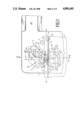
- FIG. 1 is a side view showing the area of an electrically operated can opener comprising the cutting device, including a fragment of a partly sectioned rim area of a can;
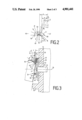
- FIG. 2 is a partial view of the cutter in the area of the cutting edge, including the geometrical representation of the cutting device;
- FIG. 3 is a partial cross sectional view of the housing of the can opener, taken along the line III--III longitudinally of the axis of rotation of the driving wheel;
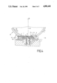
- FIG. 4 is a top plan view of the can opener, taken as indicated by the arrowed line S of FIG. 1 in the area of the cutter arrangement, yet turned through 180°.
- the can opener shown in FIG. 1 is comprised of a housing 1 on which are mounted in relatively spaced arrangement a pivot shaft 13 of a cutter 3 pivotable from an initial position 20 (shown in dot-and-dash lines) into a cutting position 28, and a driving wheel 4.
- the driving wheel 4 is driven in the direction of rotation 40 by a gearing and an electric motor not shown in the drawing.
- a cylindrical wall portion 5 of a can 24 having the lower edge 43 of its upper seam 6 resting on the periphery 45 of the driving wheel 4 while the upper edge 35 of the seam 6 takes support upon a first abutment stop 7 configured as a guide pin which is secured to the housing 1 rearwardly of the driving wheel 4, that is, on the exit side 47 when viewed in the direction of movement 12 of the can 24.
- this guide pin 7 is not shown for reasons of clarity of the representation shown in this Figure.
- the direction of movement 12 of the can 24 is understood to mean the direction in which the portion of the seam 6 abutting the cutter 3 moves.
- the cutter 3 is shown in its cutting position 28 in which its cutting edge 8 severs the lid 10 in the cutting area 9 in the immediate vicinity of the seam 6.
- the slightly downwardly bent rim of the severed lid 10 is identified by reference numeral 11.
- the cutting edge 8 has a setting angle "a" of 27.5°.
- the setting or cutting angle "a” is formed by the cutting edge 8 and the horizontal illustrated in FIGS. 1 and 2 which forms at the same time the lid 10.
- the exact pivot position of the cutter 3 in its cutting position 28 is determined by a second abutment stop 15 configured as a stop plate which is secured to the cutter 3 on its entrance side 46 and which, with the cutter in the cutting position 28, rests on the upper edge 35 of the seam 6. This enables the position of the cutter 3 to be readily adapted to different heights of the seam 6.
- a first parting surface 14 is adjacent to the cutting edge 8 in upward direction, which parting surface encloses the angle "d" with the guiding surface 30 provided on the rear side of the cutter 3 and extending substantially parallel to the wall surface 48 of the housing 1.
- a second parting surface 21 enclosing the angle "f" with the guiding surface 30 is adjacent to the first parting surface 14 further upwardly when viewing the drawing.
- the guiding surface 30 rests against the inside 39 of the wall 5 and against the radially outer cutting area 59 of the lid 10.
- edges 49, 50 which are formed at the transitions from the first parting surface 14 to the second parting surface 21 and from the second parting surface 21 to the front side 31 of the cutter 3, extend parallel to the cutting edge 8.
- these edges 49, 50 instead of extending parallel to the cutting edge 8, approach the piercing tip 17, intersecting it.
- the piercing tip 17 forms the point at the end of the cutting edge 8 nearest to the center 33 of the driving wheel 4.
- the driving wheel 4 protrudes from the wall surface 48, taking support upon the wall surface 48 via a washer 22.
- the washer 22 is mounted on the drive shaft 25 driving the driving wheel 4.
- the drive shaft 25 extends through the housing wall 51 in the bore 52 and is connected to the drive motor via a gearing not shown in the drawing.
- the driving wheel 4 is connected to the drive shaft 25 in a non-rotating relationship thereto.
- a bracket 23 secured to the housing 1 projects from the wall surface 48 in a manner embracing the driving wheel 4.
- the U-shaped bracket 23 serves to support cans 24 of particularly low height as, for example, sardine cans.
- a ledge 53 is provided on the wall surface 48 below the bracket 23, which ledge serves to support tall cans 24
- the bracket 23 and the ledge 53 serve to guide a can 24 towards the front side 31 of the cutter 3 in such an inclined position that during the cutting operation the guiding surface 30 approaches the inner surface 60 of the seam 6 as closely as possible, without being hindered by the seam. This makes it further possible to sever the lid 10 directly at the seam 6.
- teeth 27 Projecting from the periphery 45 of the driving wheel 4 are teeth 27 in saw-tooth form whereof the forward tooth flank 41, when viewed in the direction of rotation 40, is longer than the adjoining tooth flank 42.
- flank 16 extending towards the exit side 48, which flank encloses an angle "e" with the cutting edge 8.
- the cutting 8 edge is bounded by the end surface 18 which extends vertically upwardly when viewing the drawing.
- Adjacent to the flank 16 on the exit side 48 is the end surface 19 which extends parallel to the end surface 18.
- the two end surfaces 18, 19 extend at a relative distance "y" which is dimensioned such that the inside 39 of the wall 5 is in abutment with the portions 36, 37 configured as corners.
- the portions 36, 37 are radiused which, however, is not shown in the drawing.
- the cutting area 9 is to the left of the axis of rotation 26 of the driving wheel 4, while the piercing tip 17 extends approximately vertically above the axis of rotation 26 when in cutting position 28 (see FIG. 1).
- the distance between the end surface 18 and the axis of rotation 26 is smaller than the distance between the end surface 19 and the axis of rotation 26.
- the cutting area 9 is provided on the cutter 3 to the left of the vertical straight line 34 extending through the center 33 of the driving wheel 4.
- the perpendicular L1 drawn on the cutting edge 8 and intersecting the cutting area 9 extends at a distance "b" forward of the center 2 of the pivot shaft 13 of the cutter 3.
- the cutting force acting vertically on the cutting edge 8 in the cutting area 9 thereby tends to pivot the cutter 3 in clockwise direction. This tendency is counteracted by the frictional forces acting on the cutting edge 8, so that in practice the cutter 3 is moved counterclockwise during the cutting operation, that is, it is moved into the can 24.
- the cutter 3 is largely free of torques produced by the cutting operation and can therefore be held in the cutting position 28 shown with little effort by means of a counterclockwise torque produced by a control element, not shown in the drawing, which acts on the pivot center 2.
- the control element may be, for example, a lever mounted on the housing 1, which lever is operated by hand and is used for pivoting the cutter 3 into the cutting position 28 in addition to actuating a switch, not shown in the drawing, for energizing the electric motor and thus the can opener.
- a handle 38 configured as a U-shaped bracket and facilitating the handling of the can opener is provided on the housing 1 on the exit side 47.
- the mode of operation of the can opener of the invention is as follows:
- a can 24 is positioned on the periphery 45 of the driving wheel 4 with its lower edge 43 which is formed on the seam 6 at its radially outer circumference (FIG. 3).
- the seam 6 is then held captive between the cutter 3 and the driving wheel 4 such that the can 24 is no longer detachable from the can opener.
- a counterclockwise torque acting on the cutter 3 causes the piercing tip 17 to be pressed against the upper side of the lid 10 under bias.
- the driving wheel 4 starts turning in the direction of rotation 40, thereby turning the can 24 in the direction of movement 12. Due to the larger setting angle "a" of the cutting edge 8 and the displaced point of action of the forces on the piercing tip 17, the piercing operation occurs automatically, therefore requiring no appreciable application of force by the control element.
- the cutter 3 After piercing the lid 10, the cutter 3 penetrates into the lid 10 as a result of the cutting pressure and the cutting friction at its cutting edge 8 until the second abutment stop 15 is in abutment with the upper edge 35 of the seam 6.
- the predetermined tool geometry causes a resultant force "R” to act on the cutting area 9, which force exerts a counterclockwise torque on the cutter 3. This torque bears against the upper edge 35 of the seam 6 via the second abutment stop 15 in the form of the force "N".
- the can 24 thereby experiences a leftward, counterclockwise torque according to FIG.
- the cutter 3 is pivotable out of the can 24 in the same manner as described in the foregoing.
Landscapes
- Engineering & Computer Science (AREA)
- Mechanical Engineering (AREA)
- Devices For Opening Bottles Or Cans (AREA)
- Constitution Of High-Frequency Heating (AREA)
- Discharge Heating (AREA)
Applications Claiming Priority (4)
| Application Number | Priority Date | Filing Date | Title |
|---|---|---|---|
| DE3706414 | 1987-02-27 | ||
| DE3706414 | 1987-02-27 | ||
| DE3710884 | 1987-04-01 | ||
| DE3710884 | 1987-04-01 |
Publications (1)
| Publication Number | Publication Date |
|---|---|
| US4901441A true US4901441A (en) | 1990-02-20 |
Family
ID=25852990
Family Applications (1)
| Application Number | Title | Priority Date | Filing Date |
|---|---|---|---|
| US07/158,860 Expired - Fee Related US4901441A (en) | 1987-02-27 | 1988-02-22 | Can opener |
Country Status (7)
| Country | Link |
|---|---|
| US (1) | US4901441A (de) |
| EP (1) | EP0280959B1 (de) |
| KR (1) | KR910006137B1 (de) |
| AT (1) | ATE65765T1 (de) |
| CA (1) | CA1303839C (de) |
| DE (1) | DE3863941D1 (de) |
| ES (1) | ES2023225B3 (de) |
Cited By (3)
| Publication number | Priority date | Publication date | Assignee | Title |
|---|---|---|---|---|
| US5170565A (en) * | 1990-11-29 | 1992-12-15 | Moulinex (Societe Anonyme) | Can opener |
| USD444686S1 (en) | 2000-10-23 | 2001-07-10 | Hamilton Beach/Proctor-Silex, Inc. | Can opener |
| US6516524B1 (en) | 2000-10-23 | 2003-02-11 | Hamilton Beach/Proctor-Silex, Inc. | Battery operated portable can opener |
Citations (2)
| Publication number | Priority date | Publication date | Assignee | Title |
|---|---|---|---|---|
| US2975515A (en) * | 1959-12-21 | 1961-03-21 | Elvin S Land | Can opener |
| US4622749A (en) * | 1984-05-07 | 1986-11-18 | Kabushikikaisha Aichidenkikosakusho | Electric can opener |
Family Cites Families (5)
| Publication number | Priority date | Publication date | Assignee | Title |
|---|---|---|---|---|
| US1863483A (en) * | 1927-10-03 | 1932-06-14 | Glenn L Jackson | Can opener |
| DE579192C (de) * | 1932-03-19 | 1933-06-22 | Grodetzky & Polak | Vorrichtung zum Aufschneiden, insbesondere von Konservenbuechsen |
| US2024449A (en) * | 1934-01-13 | 1935-12-17 | Ernest J Hileman | Can opener |
| CH505024A (de) * | 1968-01-08 | 1971-03-31 | Metallindustrie Denkingen Gebr | Elektrisch betriebener Dosenöffner |
| US3706135A (en) * | 1969-11-08 | 1972-12-19 | Matsushita Electric Industrial Co Ltd | An electrically powered can opener |
-
1988
- 1988-02-17 DE DE8888102267T patent/DE3863941D1/de not_active Expired - Fee Related
- 1988-02-17 AT AT88102267T patent/ATE65765T1/de not_active IP Right Cessation
- 1988-02-17 ES ES88102267T patent/ES2023225B3/es not_active Expired - Lifetime
- 1988-02-17 EP EP88102267A patent/EP0280959B1/de not_active Expired - Lifetime
- 1988-02-22 US US07/158,860 patent/US4901441A/en not_active Expired - Fee Related
- 1988-02-25 CA CA000559805A patent/CA1303839C/en not_active Expired - Fee Related
- 1988-02-27 KR KR1019880002120A patent/KR910006137B1/ko not_active Expired
Patent Citations (2)
| Publication number | Priority date | Publication date | Assignee | Title |
|---|---|---|---|---|
| US2975515A (en) * | 1959-12-21 | 1961-03-21 | Elvin S Land | Can opener |
| US4622749A (en) * | 1984-05-07 | 1986-11-18 | Kabushikikaisha Aichidenkikosakusho | Electric can opener |
Cited By (3)
| Publication number | Priority date | Publication date | Assignee | Title |
|---|---|---|---|---|
| US5170565A (en) * | 1990-11-29 | 1992-12-15 | Moulinex (Societe Anonyme) | Can opener |
| USD444686S1 (en) | 2000-10-23 | 2001-07-10 | Hamilton Beach/Proctor-Silex, Inc. | Can opener |
| US6516524B1 (en) | 2000-10-23 | 2003-02-11 | Hamilton Beach/Proctor-Silex, Inc. | Battery operated portable can opener |
Also Published As
| Publication number | Publication date |
|---|---|
| EP0280959B1 (de) | 1991-07-31 |
| EP0280959A1 (de) | 1988-09-07 |
| KR880012477A (ko) | 1988-11-26 |
| DE3863941D1 (de) | 1991-09-05 |
| CA1303839C (en) | 1992-06-23 |
| ATE65765T1 (de) | 1991-08-15 |
| ES2023225B3 (es) | 1992-01-01 |
| KR910006137B1 (ko) | 1991-08-16 |
Similar Documents
| Publication | Publication Date | Title |
|---|---|---|
| US5313708A (en) | Can opener | |
| US3675321A (en) | Automatic electric can opener | |
| US4053981A (en) | Power operated can opener having automatic shutoff means, a removable hand lever assembly, and a manual crank | |
| US4625406A (en) | Safety device for a portable chain saw | |
| US4430848A (en) | Double action manual control for walk-behind mower | |
| US4734985A (en) | Portable can opener | |
| EP0137592A1 (de) | Dosenöffner | |
| EP0144508A2 (de) | Band-Rückzug und Spannvorrichtung für eine Umreifungsmaschine | |
| US3307255A (en) | Control means to energize a combination can opener and knife sharpener | |
| US4901441A (en) | Can opener | |
| CA1222370A (en) | Power pierce can opener | |
| US3955276A (en) | Electrically motor driven can opener | |
| US3949468A (en) | Compact power operated can opener with compound piercing lever, power pierce, and removable cutter mounting plate | |
| JPS6470397A (en) | Electric can opener | |
| US3006070A (en) | Can opener | |
| GB2082977A (en) | Hoop-forming apparatus for steel straps | |
| US3736659A (en) | Power operated can opener with unique thrust link | |
| US3781989A (en) | Can opener | |
| US7363711B2 (en) | Reciprocating machine tool | |
| US3277570A (en) | Electric can opener with power pierce means | |
| US3798764A (en) | Electrically powered can opener | |
| US2803057A (en) | Kitchen appliance | |
| US4077125A (en) | Automatic safety brake for chain saw | |
| US3983625A (en) | Power operated can opener having power pierce means | |
| US2932086A (en) | Can opener |
Legal Events
| Date | Code | Title | Description |
|---|---|---|---|
| AS | Assignment |
Owner name: BRAUN AKTIENGESELLSCHAFT, RUSSELSHEIMER STRASSE 22 Free format text: ASSIGNMENT OF ASSIGNORS INTEREST.;ASSIGNOR:KURZ, REINHARD;REEL/FRAME:004939/0874 Effective date: 19880129 Owner name: BRAUN AKTIENGESELLSCHAFT, A CORP. OF THE FEDERAL R Free format text: ASSIGNMENT OF ASSIGNORS INTEREST;ASSIGNOR:KURZ, REINHARD;REEL/FRAME:004939/0874 Effective date: 19880129 |
|
| FPAY | Fee payment |
Year of fee payment: 4 |
|
| REMI | Maintenance fee reminder mailed | ||
| LAPS | Lapse for failure to pay maintenance fees | ||
| FP | Lapsed due to failure to pay maintenance fee |
Effective date: 19980225 |
|
| STCH | Information on status: patent discontinuation |
Free format text: PATENT EXPIRED DUE TO NONPAYMENT OF MAINTENANCE FEES UNDER 37 CFR 1.362 |