US4899808A - Condensing surface for heat exchanger with fins arranged to drip condensate onto one side only - Google Patents
Condensing surface for heat exchanger with fins arranged to drip condensate onto one side only Download PDFInfo
- Publication number
- US4899808A US4899808A US07/141,254 US14125488A US4899808A US 4899808 A US4899808 A US 4899808A US 14125488 A US14125488 A US 14125488A US 4899808 A US4899808 A US 4899808A
- Authority
- US
- United States
- Prior art keywords
- plate
- slit
- corrugated
- heat exchanger
- flow channels
- Prior art date
- Legal status (The legal status is an assumption and is not a legal conclusion. Google has not performed a legal analysis and makes no representation as to the accuracy of the status listed.)
- Expired - Fee Related
Links
Images
Classifications
-
- F—MECHANICAL ENGINEERING; LIGHTING; HEATING; WEAPONS; BLASTING
- F28—HEAT EXCHANGE IN GENERAL
- F28F—DETAILS OF HEAT-EXCHANGE AND HEAT-TRANSFER APPARATUS, OF GENERAL APPLICATION
- F28F17/00—Removing ice or water from heat-exchange apparatus
- F28F17/005—Means for draining condensates from heat exchangers, e.g. from evaporators
-
- Y—GENERAL TAGGING OF NEW TECHNOLOGICAL DEVELOPMENTS; GENERAL TAGGING OF CROSS-SECTIONAL TECHNOLOGIES SPANNING OVER SEVERAL SECTIONS OF THE IPC; TECHNICAL SUBJECTS COVERED BY FORMER USPC CROSS-REFERENCE ART COLLECTIONS [XRACs] AND DIGESTS
- Y10—TECHNICAL SUBJECTS COVERED BY FORMER USPC
- Y10S—TECHNICAL SUBJECTS COVERED BY FORMER USPC CROSS-REFERENCE ART COLLECTIONS [XRACs] AND DIGESTS
- Y10S165/00—Heat exchange
- Y10S165/913—Condensation
Definitions
- This invention relates to heat exchangers and has particular but not necessarily exclusive reference to plate fin heat exchangers and has particular reference to heat exchangers intended for condensing at least part of a vapour to form a liquid.
- Heat exchangers are often used in circumstances where a cooling stream of vapour forms a liquid condensate which condenses onto surfaces containing or within the cooling stream.
- a great deal of effort has been expended on research and development into boiling surfaces for heat exchangers--where a liquid phase is being converted into a vapour phase--less effort has been directed heretofor towards condensing surfaces.
- the principal mechanism for improving the effectiveness of condensing surfaces has been to provide channels or ridges in the condensing surface which lead the condensed liquid to discrete parts of the surface, leaving the remainder clear of liquid and therefore able to operate more efficiently.
- Such surfaces are commonly referred to as "Grigorig" surfaces.
- the present invention is concerned with heat exchangers in which there are provided fins within the condensing path.
- the principle application of heat exchangers incorporating fins is in the so-called plate fin heat exchangers.
- a plate fin heat exchanger there is provided a series of vertically disposed, spaced, parallel plates which form a series of discrete flow paths--the flow paths being further defined by side members. Between the plates, there are disposed a series of fins, normally corrugated fins, and the assembly may be clamped together or is preferably bonded together.
- plate fin heat exchangers are made from aluminium or aluminium alloys and may be joined together by means of salt bath brazing or vacuum brazing. Plate fin heat exchanger constructions are well known per se.
- a heat exchanger having a first path or a first fluid which, in use, increases in heat content, and a second path or a second fluid which, in use, decreases in heat content, the heat exchanger being adapted and arranged to reduce the heat content of a second fluid, which includes vapour which condenses to form a liquid, characterised in that the second path includes a plurality of fins, which are so disposed that condensate forming on a first fin or set of fins upstream of and above a second fin or set of fins falls onto one side only of the second fin or set of fins.
- the fins are preferably interconnected in the form of corrugations located between adjacent plates to form a plate-fin heat exchanger with the peaks and troughs of the corrugations in contact with or closely adjacent to the plates, and the fins being formed on the portions of the corrugations between the peaks and troughs.
- the corrugations may be substantially square wave corrugations when seen in plan view.
- the lower edges of a block of the fins all extending to one side of the fins.
- the fins may be in the form of corrugated sheets with the corrugations being arranged at angles one to the other.
- the ends of the fins may be deformed sideways so that liquid condensate from the first fin or set of fins falls only onto one side of the second fin or set of fins. Both ends of the fin may be deformed sideways.
- the present invention also provides a corrugation for a plate fin type heat exchanger in which there is a plurality of slits in the corrugations between the peaks and troughs, the edges of the slits being deformed out of the plane of the material of the strips.
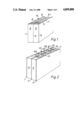
- FIGS. 1 and 2 are schematic perspective views of a section of a plate fin type heat exchanger
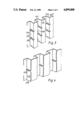
- FIGS. 3 and 4 are perspective views of a form of fin
- FIGS. 5 and 6 are sectional views of the corrugations similar to those shown in FIGS. 3 and 4, and
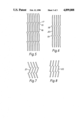
- FIGS. 7 and 8 are views of further alternative forms of fin.
- this shows schematically a plate fin heat exchanger in which three plates 1, 2 and 3 are disposed in spaced arrangement with edge separators 4 and 5 holding the plates apart.
- the plates define a pair of flow paths 6, 7 with corrugations 8, 9 located in the flow paths.
- the flow path 6 is adapted to accept a downwardly passing stream of fluid 10 and the flow path 7 is adapted to accept an upwardly flowing stream of fluid 11.
- Suitable end stops and tanks are provided within the plate fin heat exchanger in a manner well known per se to enable the fluids to be passed through the heat exchanger as shown.
- the fluid passing vertically downward through the heat exchanger is being cooled by the fluid passing upwardly through the heat exchanger.
- the fluid 10 contains products which, on cooling, will condense within the heat exchanger. Some or all of the fluid may be condensed within the heat exchanger. Normally, the cooling will reduce the temperature of the fluid, but, of course, when a vapour is condensing to form a liquid, heat content can be removed without change of temperature as the vapour phase changes state to the liquid phase. Condensation can occur either on the plates 1, 2 or on the corrugated fins 8.
- FIG. 2 shows a view similar to that of FIG. 1, save for the fact that the corrugation 8a is of substantially square cross-section when seen in plan view.
- This square wave corrugation has a portion 100 which forms a wave peak and a portion 101 which forms a wave trough. Between the peaks and troughs is a series of portions 102 which are substantially at right-angles to the plates 1 and 2.
- the fins may have a shape as is shown more clearly in FIGS. 3 to 8.
- this shows the rectangular corrugation of the assembly of FIG. 2.
- the peaks 100 and troughs 101 are normally bonded to the plates 1, 2 in the conventional manner.
- corrugations strengthen the heat exchanger and help it resist internal pressures.
- the portions 102 of the corrugation which are between the peaks and troughs are slit at a series of transverse positions 103, 104.
- portions of the corrugations can be deformed so as to form slots.
- edges 108, 109 are both deformed so that the portion 110 is kept clean of condensate. This deformation of the upper and lower sides of the fins is an alternative embodiment of the invention.
- FIGS. 5 and 6 are cross-sections of fins similar to those illustrated in FIGS. 3 and 4 and it can be seen that the upper edges 15 of fin 16 are deformed to the left so that condensate dropping from edge 17 keeps clear of the left hand side of the fins. Similarly, in the embodiment illustrated in FIG. 6 both upper and lower edges are deformed at 18 and 19 to keep surface 20 clear. It will be appreciated that FIG. 6 corresponds to a cross-section of the corrugated fin shown in FIG. 4.
- the fins may be inclined in a herring bone fashion as is shown at 21 in FIG. 7.
- the fins may be simply inclined as is shown in FIG. 8 at 22.
- the plate fin heat exchanger may be constructed in a manner known per se, by example vacuum brazing or salt bath brazing.
- the vacuum brazed structure is preferred.
Landscapes
- Engineering & Computer Science (AREA)
- Physics & Mathematics (AREA)
- Thermal Sciences (AREA)
- Mechanical Engineering (AREA)
- General Engineering & Computer Science (AREA)
- Heat-Exchange Devices With Radiators And Conduit Assemblies (AREA)
Abstract
Description
Claims (7)
Applications Claiming Priority (2)
| Application Number | Priority Date | Filing Date | Title |
|---|---|---|---|
| GB8700801 | 1987-01-14 | ||
| GB878700801A GB8700801D0 (en) | 1987-01-14 | 1987-01-14 | Heat exchanger |
Publications (1)
| Publication Number | Publication Date |
|---|---|
| US4899808A true US4899808A (en) | 1990-02-13 |
Family
ID=10610680
Family Applications (1)
| Application Number | Title | Priority Date | Filing Date |
|---|---|---|---|
| US07/141,254 Expired - Fee Related US4899808A (en) | 1987-01-14 | 1988-01-06 | Condensing surface for heat exchanger with fins arranged to drip condensate onto one side only |
Country Status (3)
| Country | Link |
|---|---|
| US (1) | US4899808A (en) |
| JP (1) | JPS63189784A (en) |
| GB (2) | GB8700801D0 (en) |
Cited By (11)
| Publication number | Priority date | Publication date | Assignee | Title |
|---|---|---|---|---|
| US5031693A (en) * | 1990-10-31 | 1991-07-16 | Sundstrand Corporation | Jet impingement plate fin heat exchanger |
| US5333683A (en) * | 1991-12-11 | 1994-08-02 | L'air Liquide, Societe Anonyme Pour L'etude Et L'exploitation Des Procedes Georges Claude | Indirect heat exchanger |
| US6253840B1 (en) * | 1998-02-10 | 2001-07-03 | Denso Corporation | Refrigerant evaporator including refrigerant passage with inner fin |
| US20040099408A1 (en) * | 2002-11-26 | 2004-05-27 | Shabtay Yoram Leon | Interconnected microchannel tube |
| US20050121181A1 (en) * | 2002-01-17 | 2005-06-09 | Claire Szulman | Heat exchange fin and the production method thereof |
| WO2015188266A1 (en) * | 2014-06-10 | 2015-12-17 | Vmac Global Technology Inc. | Methods and apparatus for simultaneously cooling and separating a mixture of hot gas and liquid |
| US10107553B2 (en) | 2015-04-17 | 2018-10-23 | Denso Corporation | Heat exchanger |
| US20200141663A1 (en) * | 2018-11-05 | 2020-05-07 | Hamilton Sundstrand Corporation | Additively manufactured fin slots for thermal growth |
| WO2020100687A1 (en) * | 2018-11-13 | 2020-05-22 | 株式会社デンソー | Heat exchanger |
| JP2020079693A (en) * | 2018-11-13 | 2020-05-28 | 株式会社デンソー | Heat exchanger |
| US20230392880A1 (en) * | 2022-06-03 | 2023-12-07 | Raytheon Technologies Corporation | Conformal heat exchanger |
Families Citing this family (4)
| Publication number | Priority date | Publication date | Assignee | Title |
|---|---|---|---|---|
| WO2011158371A1 (en) * | 2010-06-18 | 2011-12-22 | トヨタ自動車株式会社 | Cooler |
| GB2497789A (en) * | 2011-12-21 | 2013-06-26 | Sharp Kk | Heat and mass exchanger for liquid desiccant air conditioners |
| JP2016135049A (en) * | 2015-01-21 | 2016-07-25 | 東芝三菱電機産業システム株式会社 | Hermetically sealed rotary electric machine |
| WO2016166963A1 (en) * | 2015-04-17 | 2016-10-20 | 株式会社デンソー | Heat exchanger |
Citations (19)
| Publication number | Priority date | Publication date | Assignee | Title |
|---|---|---|---|---|
| SU340866A1 (en) * | И. В. Тишин, П. Медведев , О. А. Дроздов | SURFACE HEAT EXCHANGE | ||
| US1969439A (en) * | 1933-09-22 | 1934-08-07 | Wentworth | Radiator |
| US2011853A (en) * | 1932-07-25 | 1935-08-20 | Gen Motors Corp | Radiator core |
| DE635688C (en) * | 1933-03-01 | 1936-09-22 | Valerie Strasser Geb Kablitz | Cast iron plate heat exchanger |
| GB521285A (en) * | 1937-11-15 | 1940-05-16 | Martin Larsen | Improvements in or relating to plate heat exchanging apparatus |
| US2285225A (en) * | 1941-01-16 | 1942-06-02 | Gen Electric | Flat tube condenser |
| SE132411C1 (en) * | 1948-03-04 | 1951-07-17 | ||
| FR1018691A (en) * | 1949-06-22 | 1953-01-12 | Ljungstroms Angturbin Ab | Set of elements for air heaters |
| GB872255A (en) * | 1958-03-10 | 1961-07-05 | Ici Ltd | Heat exchange apparatus |
| GB1256964A (en) * | 1968-06-28 | 1971-12-15 | ||
| GB1343175A (en) * | 1970-09-11 | 1974-01-10 | Borg Warner | Vertical surface vapour condensers |
| GB1375503A (en) * | 1971-03-08 | 1974-11-27 | ||
| US4182410A (en) * | 1976-02-28 | 1980-01-08 | Hisaka Works Ltd. | Plate type condenser |
| JPS5589695A (en) * | 1978-12-26 | 1980-07-07 | Clarion Co Ltd | Heat exchanger |
| US4228850A (en) * | 1977-11-08 | 1980-10-21 | Hisaka Works, Ltd. | Plate used in condenser |
| SU1035398A1 (en) * | 1981-03-04 | 1983-08-15 | Ленинградский технологический институт холодильной промышленности | Plate-type heat exchanger |
| US4648441A (en) * | 1984-10-30 | 1987-03-10 | U.S. Philips Corporation | Heat exchanger comprising a finned pipe |
| US4715431A (en) * | 1986-06-09 | 1987-12-29 | Air Products And Chemicals, Inc. | Reboiler-condenser with boiling and condensing surfaces enhanced by extrusion |
| US4729428A (en) * | 1984-06-20 | 1988-03-08 | Showa Aluminum Corporation | Heat exchanger of plate fin type |
-
1987
- 1987-01-14 GB GB878700801A patent/GB8700801D0/en active Pending
-
1988
- 1988-01-06 US US07/141,254 patent/US4899808A/en not_active Expired - Fee Related
- 1988-01-08 GB GB8800385A patent/GB2199933B/en not_active Expired - Fee Related
- 1988-01-12 JP JP63004646A patent/JPS63189784A/en active Pending
Patent Citations (20)
| Publication number | Priority date | Publication date | Assignee | Title |
|---|---|---|---|---|
| SU340866A1 (en) * | И. В. Тишин, П. Медведев , О. А. Дроздов | SURFACE HEAT EXCHANGE | ||
| US2011853A (en) * | 1932-07-25 | 1935-08-20 | Gen Motors Corp | Radiator core |
| DE635688C (en) * | 1933-03-01 | 1936-09-22 | Valerie Strasser Geb Kablitz | Cast iron plate heat exchanger |
| US1969439A (en) * | 1933-09-22 | 1934-08-07 | Wentworth | Radiator |
| GB521285A (en) * | 1937-11-15 | 1940-05-16 | Martin Larsen | Improvements in or relating to plate heat exchanging apparatus |
| US2285225A (en) * | 1941-01-16 | 1942-06-02 | Gen Electric | Flat tube condenser |
| SE132411C1 (en) * | 1948-03-04 | 1951-07-17 | ||
| FR1018691A (en) * | 1949-06-22 | 1953-01-12 | Ljungstroms Angturbin Ab | Set of elements for air heaters |
| GB872255A (en) * | 1958-03-10 | 1961-07-05 | Ici Ltd | Heat exchange apparatus |
| GB1256964A (en) * | 1968-06-28 | 1971-12-15 | ||
| GB1343175A (en) * | 1970-09-11 | 1974-01-10 | Borg Warner | Vertical surface vapour condensers |
| GB1375503A (en) * | 1971-03-08 | 1974-11-27 | ||
| US4182410A (en) * | 1976-02-28 | 1980-01-08 | Hisaka Works Ltd. | Plate type condenser |
| GB1570728A (en) * | 1976-02-28 | 1980-07-09 | Hisaka Works Ltd | Condenser heat exchange surfaces |
| US4228850A (en) * | 1977-11-08 | 1980-10-21 | Hisaka Works, Ltd. | Plate used in condenser |
| JPS5589695A (en) * | 1978-12-26 | 1980-07-07 | Clarion Co Ltd | Heat exchanger |
| SU1035398A1 (en) * | 1981-03-04 | 1983-08-15 | Ленинградский технологический институт холодильной промышленности | Plate-type heat exchanger |
| US4729428A (en) * | 1984-06-20 | 1988-03-08 | Showa Aluminum Corporation | Heat exchanger of plate fin type |
| US4648441A (en) * | 1984-10-30 | 1987-03-10 | U.S. Philips Corporation | Heat exchanger comprising a finned pipe |
| US4715431A (en) * | 1986-06-09 | 1987-12-29 | Air Products And Chemicals, Inc. | Reboiler-condenser with boiling and condensing surfaces enhanced by extrusion |
Cited By (18)
| Publication number | Priority date | Publication date | Assignee | Title |
|---|---|---|---|---|
| US5031693A (en) * | 1990-10-31 | 1991-07-16 | Sundstrand Corporation | Jet impingement plate fin heat exchanger |
| US5333683A (en) * | 1991-12-11 | 1994-08-02 | L'air Liquide, Societe Anonyme Pour L'etude Et L'exploitation Des Procedes Georges Claude | Indirect heat exchanger |
| US6253840B1 (en) * | 1998-02-10 | 2001-07-03 | Denso Corporation | Refrigerant evaporator including refrigerant passage with inner fin |
| US20050121181A1 (en) * | 2002-01-17 | 2005-06-09 | Claire Szulman | Heat exchange fin and the production method thereof |
| US7445040B2 (en) * | 2002-01-17 | 2008-11-04 | L'air Liquide, Societe Anonyme A Directoire Et Conseil De Surveillance Pour L'etude Et L'exploitation Des Procedes Georges Claude | Heat exchange fin and the production method thereof |
| US20040099408A1 (en) * | 2002-11-26 | 2004-05-27 | Shabtay Yoram Leon | Interconnected microchannel tube |
| US20050241816A1 (en) * | 2002-11-26 | 2005-11-03 | Shabtay Yoram L | Interconnected microchannel tube |
| GB2542717A (en) * | 2014-06-10 | 2017-03-29 | Vmac Global Tech Inc | Methods and apparatus for simultaneously cooling and separating a mixture of hot gas and liquid |
| WO2015188266A1 (en) * | 2014-06-10 | 2015-12-17 | Vmac Global Technology Inc. | Methods and apparatus for simultaneously cooling and separating a mixture of hot gas and liquid |
| US10995995B2 (en) | 2014-06-10 | 2021-05-04 | Vmac Global Technology Inc. | Methods and apparatus for simultaneously cooling and separating a mixture of hot gas and liquid |
| US10107553B2 (en) | 2015-04-17 | 2018-10-23 | Denso Corporation | Heat exchanger |
| US20200141663A1 (en) * | 2018-11-05 | 2020-05-07 | Hamilton Sundstrand Corporation | Additively manufactured fin slots for thermal growth |
| US10845132B2 (en) * | 2018-11-05 | 2020-11-24 | Hamilton Sundstrand Corporation | Additively manufactured fin slots for thermal growth |
| WO2020100687A1 (en) * | 2018-11-13 | 2020-05-22 | 株式会社デンソー | Heat exchanger |
| JP2020079693A (en) * | 2018-11-13 | 2020-05-28 | 株式会社デンソー | Heat exchanger |
| US12163744B2 (en) | 2018-11-13 | 2024-12-10 | Denso Corporation | Heat exchanger |
| US20230392880A1 (en) * | 2022-06-03 | 2023-12-07 | Raytheon Technologies Corporation | Conformal heat exchanger |
| US12209819B2 (en) * | 2022-06-03 | 2025-01-28 | Rtx Corporation | Conformal heat exchanger |
Also Published As
| Publication number | Publication date |
|---|---|
| GB2199933B (en) | 1990-11-14 |
| GB2199933A (en) | 1988-07-20 |
| JPS63189784A (en) | 1988-08-05 |
| GB8800385D0 (en) | 1988-02-10 |
| GB8700801D0 (en) | 1987-02-18 |
Similar Documents
| Publication | Publication Date | Title |
|---|---|---|
| US4899808A (en) | Condensing surface for heat exchanger with fins arranged to drip condensate onto one side only | |
| US5709264A (en) | Heat exchanger | |
| US3983191A (en) | Brazed plate-type heat exchanger for nonadiabatic rectification | |
| JP3561175B2 (en) | Plate-fin heat exchanger in downflow reboiler of two-column air separation plant, method of assembling the same, and low-temperature air separation device having the same | |
| US3840070A (en) | Evaporator-condenser | |
| US4580623A (en) | Heat exchanger | |
| EP1398593B1 (en) | Plate-fin exchangers with textured surfaces | |
| US7032654B2 (en) | Plate heat exchanger with enhanced surface features | |
| EP0275029B1 (en) | Multi-zone boiling process and apparatus | |
| CN1321313C (en) | Heat exchange fin and manufacturing method thereof | |
| US7059397B2 (en) | Heat exchanger with brazed plates | |
| US4699209A (en) | Heat exchanger design for cryogenic reboiler or condenser service | |
| JPH0454879B2 (en) | ||
| EP0415584B1 (en) | Stack type evaporator | |
| CN101341372A (en) | A new corrugated heat exchanger and its application | |
| US4574007A (en) | Fractionating apparatus | |
| JPH09119783A (en) | Contact device of liquid-steam | |
| US5718127A (en) | Liquid vapor contact apparatus | |
| RU2294504C2 (en) | Heat exchange plate, plate stack, and plate heat exchanger | |
| JPH0755380A (en) | Heat exchanger | |
| JPH01310297A (en) | Plate fin for heat exchanger and fin tube type heat exchanger | |
| CN101137882B (en) | Plate type heat exchanger | |
| US20250389495A1 (en) | Brazed plate heat exchanger | |
| JP2000097590A (en) | Plate heat exchanger | |
| EP0155772A1 (en) | Heat exchanger |
Legal Events
| Date | Code | Title | Description |
|---|---|---|---|
| AS | Assignment |
Owner name: MARSTON PALMER LIMITED, WOBASTON ROAD, FORDHOUSES, Free format text: ASSIGNMENT OF ASSIGNORS INTEREST.;ASSIGNORS:GREGORY, EDWARD J.;FELTON, JOHN;COOPER, FRANK T.;REEL/FRAME:004843/0774 Effective date: 19871216 Owner name: MARSTON PALMER LIMITED, A CORP. OF GREAT BRITAIN Free format text: ASSIGNMENT OF ASSIGNORS INTEREST;ASSIGNORS:GREGORY, EDWARD J.;FELTON, JOHN;COOPER, FRANK T.;REEL/FRAME:004843/0774 Effective date: 19871216 |
|
| REMI | Maintenance fee reminder mailed | ||
| LAPS | Lapse for failure to pay maintenance fees | ||
| FP | Expired due to failure to pay maintenance fee |
Effective date: 19940213 |
|
| STCH | Information on status: patent discontinuation |
Free format text: PATENT EXPIRED DUE TO NONPAYMENT OF MAINTENANCE FEES UNDER 37 CFR 1.362 |