US4899641A - Electro-hydraulic helicopter system having individual blade control - Google Patents
Electro-hydraulic helicopter system having individual blade control Download PDFInfo
- Publication number
- US4899641A US4899641A US07/194,400 US19440088A US4899641A US 4899641 A US4899641 A US 4899641A US 19440088 A US19440088 A US 19440088A US 4899641 A US4899641 A US 4899641A
- Authority
- US
- United States
- Prior art keywords
- control signals
- grooves
- hydraulic
- communicating
- groove
- Prior art date
- Legal status (The legal status is an assumption and is not a legal conclusion. Google has not performed a legal analysis and makes no representation as to the accuracy of the status listed.)
- Expired - Lifetime
Links
- 239000012530 fluid Substances 0.000 claims description 20
- 238000006073 displacement reaction Methods 0.000 claims description 8
- 238000002955 isolation Methods 0.000 claims description 5
- 230000001154 acute effect Effects 0.000 claims 1
- 125000004122 cyclic group Chemical group 0.000 description 8
- 239000002131 composite material Substances 0.000 description 6
- 230000003416 augmentation Effects 0.000 description 3
- 238000012545 processing Methods 0.000 description 3
- 238000007792 addition Methods 0.000 description 2
- 230000003321 amplification Effects 0.000 description 2
- 230000009977 dual effect Effects 0.000 description 2
- 230000000694 effects Effects 0.000 description 2
- 230000006870 function Effects 0.000 description 2
- 238000003199 nucleic acid amplification method Methods 0.000 description 2
- RZVHIXYEVGDQDX-UHFFFAOYSA-N 9,10-anthraquinone Chemical compound C1=CC=C2C(=O)C3=CC=CC=C3C(=O)C2=C1 RZVHIXYEVGDQDX-UHFFFAOYSA-N 0.000 description 1
- 206010035148 Plague Diseases 0.000 description 1
- 241000607479 Yersinia pestis Species 0.000 description 1
- 239000006096 absorbing agent Substances 0.000 description 1
- 230000003190 augmentative effect Effects 0.000 description 1
- 238000004891 communication Methods 0.000 description 1
- 230000001010 compromised effect Effects 0.000 description 1
- 230000002950 deficient Effects 0.000 description 1
- 238000013461 design Methods 0.000 description 1
- 238000010586 diagram Methods 0.000 description 1
- 230000003292 diminished effect Effects 0.000 description 1
- 230000005284 excitation Effects 0.000 description 1
- 239000000835 fiber Substances 0.000 description 1
- 230000001939 inductive effect Effects 0.000 description 1
- 238000009434 installation Methods 0.000 description 1
- 230000014759 maintenance of location Effects 0.000 description 1
- 239000000463 material Substances 0.000 description 1
- 230000007935 neutral effect Effects 0.000 description 1
- 230000003287 optical effect Effects 0.000 description 1
- 230000004044 response Effects 0.000 description 1
- 229920006395 saturated elastomer Polymers 0.000 description 1
- 238000007789 sealing Methods 0.000 description 1
- 238000004088 simulation Methods 0.000 description 1
- 230000006641 stabilisation Effects 0.000 description 1
- 238000011105 stabilization Methods 0.000 description 1
- 238000012546 transfer Methods 0.000 description 1
- 238000013519 translation Methods 0.000 description 1
Images
Classifications
-
- B—PERFORMING OPERATIONS; TRANSPORTING
- B64—AIRCRAFT; AVIATION; COSMONAUTICS
- B64C—AEROPLANES; HELICOPTERS
- B64C27/00—Rotorcraft; Rotors peculiar thereto
- B64C27/54—Mechanisms for controlling blade adjustment or movement relative to rotor head, e.g. lag-lead movement
-
- B—PERFORMING OPERATIONS; TRANSPORTING
- B64—AIRCRAFT; AVIATION; COSMONAUTICS
- B64C—AEROPLANES; HELICOPTERS
- B64C27/00—Rotorcraft; Rotors peculiar thereto
- B64C27/54—Mechanisms for controlling blade adjustment or movement relative to rotor head, e.g. lag-lead movement
- B64C27/72—Means acting on blades
- B64C2027/7205—Means acting on blades on each blade individually, e.g. individual blade control [IBC]
- B64C2027/7211—Means acting on blades on each blade individually, e.g. individual blade control [IBC] without flaps
- B64C2027/7216—Means acting on blades on each blade individually, e.g. individual blade control [IBC] without flaps using one actuator per blade
-
- Y—GENERAL TAGGING OF NEW TECHNOLOGICAL DEVELOPMENTS; GENERAL TAGGING OF CROSS-SECTIONAL TECHNOLOGIES SPANNING OVER SEVERAL SECTIONS OF THE IPC; TECHNICAL SUBJECTS COVERED BY FORMER USPC CROSS-REFERENCE ART COLLECTIONS [XRACs] AND DIGESTS
- Y02—TECHNOLOGIES OR APPLICATIONS FOR MITIGATION OR ADAPTATION AGAINST CLIMATE CHANGE
- Y02T—CLIMATE CHANGE MITIGATION TECHNOLOGIES RELATED TO TRANSPORTATION
- Y02T50/00—Aeronautics or air transport
- Y02T50/30—Wing lift efficiency
Definitions
- This invention relates to electro-hydraulic helicopter control systems and more particularly to a full authority electro-hydraulic control system having a hydraulic slip ring providing individual blade control.
- helicopter flight is primarily controlled by cyclic and collective control inputs to the rotating helicopter blades, usually through a common mechanical input such as a swash plate. Input and transfer of these control signals to the rotating blades is most often accomplished by an exclusively mechanical arrangement of levers, mixers and cranks.
- Some known control systems modify the mechanical arrangements by the addition of a hydraulic boost mechanism to provide amplification of the mechanical input signals.
- Other control systems are mechanical with auxiliary hydraulic amplification, but lack a direct mechanical connection between the control stick that inputs the signals to control the helicopter blades.
- the predominant frequency of excitation is the "nth" harmonic of an n bladed rotor.
- the predominant frequency of the vibration is the fourth harmonic or four per rev.
- a helicopter control system It would be advantageous for a helicopter control system to be fully hydraulic allowing for individual blade control and allowing for auxiliary blade tracking higher harmonic and trim force control inputs using exclusively electrical or optical input signals and hydraulic controls.
- the present invention is directed toward such a system.
- An object of the present invention is to provide for a helicopter control system which allows for individual blade control.
- Another object of the present invention is to provide a helicopter control system which is fully hydraulic.
- an apparatus used in providing fluid control signals of a first element to a moveable second element include a first member having an outer surface formed with a plurality of grooves, each receiving respective fluid control signals by means of corresponding channels formed in said first member interior.
- the apparatus also includes a second member adapted to receive, at an inner surface thereof, the first member outer surface.
- the second member inner surface has a plurality of grooves each communicating with corresponding second member interior channels and each in registration with a corresponding first member groove.
- a second member is moveable relative to the first member, with the registered first and second member grooves continuously communicating the fluid control signals throughout the displacement.
- the valving means selectively provides fluid control signals.
- An interface apparatus is included for communicating the control signals from the first element to the second element.
- the apparatus includes a first member having an outer surface formed with a plurality of grooves each for receiving from respective interior channels fluid control signals, and the second member adapted to receive at an inner surface thereof the first member outer surface.
- the second member inner surface having a plurality of grooves communicating with second member interior channels and each in registration with a corresponding first member groove.
- the second member is moveable relative to the first member.
- the registered first and second member grooves continuously communicate the fluid control signals throughout any second member movement.
- an actuator means configured with the moving second element for receiving the control signals from the interface means and generating displacements in dependence thereon.
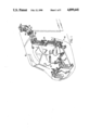
- FIG. 1 is a simplified schematic illustration showing a portion of a mechanical control system found in the prior art.
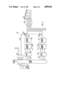
- FIG. 2 is a simplified illustration of a portion of a hydraulic control system provided according to the present invention.
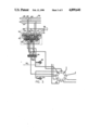
- FIG. 3 is a schematic illustration of a hydraulic circuit found in the control system of FIG. 2.
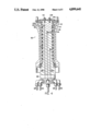
- FIG. 4 is a sectioned illustration of a portion of the hydraulic slip ring of the system of FIG. 2.
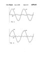
- FIG. 5 illustrates diagrammatically a composite output control signal comprised of a cyclic pitch signal with a two per rev higher harmonic input signal superimposed thereon.
- FIG. 6 illustrates a composite output control signal having a four per rev signal superimposed on a cyclic pitch control signal.
- FIG. 1 shows a portion of a mechanical control system 10 used in a helicopter 12, shown in phantom.
- the control system is an example of a known mechanical control system and is comprised of a plurality of levers, bellcranks, control rods and other such mechanical devices needed to translate control signals provided by a pilot at control stick 14 to adjust the pitch of helicopter blades (not shown) rotating above swash plate 16.
- the swash plate is a rotary coupler which will transmit mechanical displacement received on control rods 18, 20 and 22 to actuators on the rotating helicopter blades.
- the helicopter control system of FIG. 1 also incorporates automatic stabilization equipment (ASE) 24 which provides in a known manner stability augmentation and higher harmonic control signals which are superimposed on the input control signal.
- ASE automatic stabilization equipment
- the exact same composite control signal must then be applied simultaneously to each of the rotating helicopter blades. That is, no helicopter blade can be addressed individually.
- the hydraulic control system 26 includes a central processing unit (CPU) 28 and memory 30 which contain flight control algorithms. External pilot command signals are presented on line 31. Helicopter parameter signals are presented on lines 32 to input/output interface 34 are then processed by the CPU. For a typical four bladed helicopter the input signals include signals indicative of the following parameters:
- the central processing unit will, in accordance with control algorithms provide output control signals to a servo amplifier 36 on lines 38. These control signals will then operate a plurality of electro hydraulic valves which comprise part of control module 40.
- the hydraulic control module is configured with two hydraulic systems (c 1 ,c 2 ) each comprising a source 41 and return 42 line which are selected by system switching valve 43.
- the hydraulic signals are presented on either lines 44 or 46.
- a transducer preferably a rotary variable differential transducer (RVDT) or LVDT for a linear actuator, is included to provide actuator simulation and outputs on line 50 a feedback signal to the central processing unit.
- RVDT rotary variable differential transducer
- LVDT linear actuator
- the hydraulic control signal is presented through a hydraulic slip ring 52, detailed hereinafter to a hydraulic actuator 54 located on the rotating helicopter blades.
- a hydraulic slip ring 52 located on the rotating helicopter blades.
- FIG. 2 the system components for only two helicopter blades are illustrated in FIG. 2, there will be a two additional control elements generating control signals on respective line for a four bladed helicopter, as shown in FIG. 2.
- the hydraulic circuit 56 used in the control system of FIG. 2.
- the hydraulic circuit includes primary and secondary hydraulic systems (c 1 ,c 2 ) each comprised of a pressure 58,60 and return 62,64 hydraulic lines.
- Each helicopter blade has a control module 66 that includes a plurality of electro-hydraulic valves 68, 70 and 72 configured in a known fashion to provide two levels of redundancy.
- a control module 66 that includes a plurality of electro-hydraulic valves 68, 70 and 72 configured in a known fashion to provide two levels of redundancy.
- Differential transducers 74, 76 and 78 are installed between each of the primary and secondary system pressure lines and monitor the operation of that channel. In case of conflict between the channels (e.g. a failure of the valve) the two channels with similar values of pressure difference will "out vote" the third channel.
- This function is performed by the switching solenoid valve positioned downstream of the electro-hydraulic in the control module. The solenoid triggers the bypass of the electro-hydraulic valve pressure 1 and pressure 2 lines in the defective channel.
- each of the electro-hydraulic valves in the system is capable of operating the primary and secondary hydraulic systems of the helicopter.
- the hydraulic circuit comprising the hydraulic control modules are connected to the primary and secondary hydraulic systems in the helicopter. Both of the systems are driven from the combining gearbox for a multi-engine helicopter or from the accessories gearbox in a case of a single engine helicopter.
- the primary system pressure is ported through a filter (not shown) to the electro-hydraulic valves and to the pressure port on the main control valve.
- the secondary system is similarly connected to an electro-hydraulic valve and the secondary control pressure port on the main control valve.
- a difference in pressure is produced between the hydraulic inputs for a particular electro-hydraulic valve.
- This difference in pressure moves a spool 82 in the control module. This movement connects one of the actuator cylinder ports to the system pressure and the other port to the return through the system switching valve 43.
- the spool 82 has a set of centering springs which bring it to a neutral position in the absence of a pressure differential thereacross.
- the main control valve spool MCV transducer 48 is connected through a synchronizing link to the (LVDT) installed to monitor the MCV spool position.
- the system switching valve 43 receives the primary system pressure at one end of spool 84 which comprises part of the system switch valve 43.
- the spool disconnects the secondary system actuator cylinder lines coming from the main control module to that of the actuator.
- the spool valve shuttles due to a spring installed in the system and disconnects the primary system cylinder lines from the control module to that of the actuator and simultaneously connects the secondary system main control valve lines to that of the actuator lines to accomplish the desired redundancy.
- An embodiment which includes dual tandem control the system switching valve is deleted and all four cylinder lines are connected to the four cylinder lines of the dual tandem system.
- actuator simulator port 1 One output from the system switching valve is received by actuator simulator port 1.
- the second port of the actuator simulator is connected to the input cylinder port for the respective actuator channel stator of the hydraulic slip ring.
- the second line from the system switching valve is directly connected to the second cylinder port in the stator of the hydraulic slip ring. This connection is repeated for the rest of the three control modules in the four bladed helicopter of FIG. 2.
- the actuator simulator and feedback RVDT is positioned on the fuselage to avoid installation of feedback devices in a rotating system and carrying feedback signal through an electrical slip ring which would increase sophistication and contribute to electrical noise.
- the main control valve comprises a lap, spool and sleeve assembly installed in a split manifold isolating the two hydraulic systems.
- the solenoid operated bypass valves are conventional and are the type used in aircraft hydraulic systems.
- the electro-hydraulic valves are of a conventional type used in fly by wire control systems and in auto pilots.
- control modules are remotely located in the preferred embodiment and present a dynamic stiffness problem which is solved by wrapping the lines with preloaded fiber. This is the same principle used in the design of composite Kevlar-wrapped hydraulic accumulator bodies. In addition to the electro hydraulic redundancies, an actuator will have built-in dynamic biases for a safe autorotation in case of total electrical and hydraulic failure.
- the output hydraulic signal from one of the cylinder ports in the hydraulic control module in the form of cylinder pressure and flow is presented through the control actuator simulator 48 which has identical characteristics to the main actuator.
- a feedback transducer (RVDT or LVDT) is configured with the simulator and provides feedback signals on lines 50 to the CPU.
- Hydraulic control signals are provided along respective lines to the rotating system through the hydraulic slip ring 52.
- the hydraulic slip ring is configured with nine channels, and presents the hydraulic control signals to actuators represented schematically by actuator 54 which can be either of a linear or rotary type.
- the hydraulic slip ring comprises an outer rotor 86 which is configured to be received by an inner stator 88.
- the stator consists of twelve concentric flow channels each set of two channels for one blade pitch, horn or hinge line actuator. Positioned next to these two channels in the slip ring is a return line groove. This configuration is repeated for each of the next three helicopter blades.
- the return groove between each set of blades actuator lines picks up the lap leakage and also provides system isolation.
- Each of the 12 grooves is sandwiched between a set of "O" ring grooves per MIL-G-5514F.
- the stator and rotor of the slip ring are lap fitted to provide redundant system isolation apart from the primary sealing done by either "O" rings or piston rings.
- hydraulic control signals are presented on lines 90,92 with pressure and return lines 94,96 also shown.
- the hydraulic slip ring is preferably configured with a plurality of inner bores or channels, such as bores 98 and 100, which sources and returns hydraulic control signals presented in the manner described hereinabove.
- the hydraulic control signals are, for example, presented at outer groove 102.
- a corresponding groove 103 is configured in the rotor and provides the hydraulic control signals thereacross to channel 104 in the rotor and eventually to the corresponding helicopter blade actuator.
- End cap 106 is positioned with the rotor to locate the rotor via retention bolts 108 and 110.
- Each of the registered flow and return grooves in both the rotor and stator are preferably formed with a scalloped configuration.
- Those skilled in the art will note that right angles connecting channels in the rotor or stator to the flow grooves will lead to fatigue in the rotating member. The scalloped portion reduces the material fatigue.
- FIG. 4 Also shown in FIG. 4 are a plurality of seals such as rod seal 112 and GLYD ring 114.
- a rod seal is conventional and performs its known function. It is preferable to configure the flow grooves and return grooves to be separated by a common system return 116, as well as by "O" rings 118. This configuration of separating the pressure line from its corresponding return line by "O" rings and an intermediate common return line collects lap leakage and further prevents communication between adjacent channels in the event of a seal component failure.
- the collective input signal generated from the transducer on the pilot's collective controller stick is scaled by the CPU to give full helicopter blade travel.
- the cyclic pitch signal is generated on the cyclic of stick controller by having two transducers approximately 90 degrees apart to resolve the longitudinal and lateral components of a pilots input command. Both of the outputs of the transducers are scaled to represent their respective control authority for maximum amplitude relative to the input signal magnitude.
- the combined signal waveform generated by collective longitudinal and lateral signal inputs is modified by the stability augmentation inputs, auto pilot inputs, higher harmonic inputs and miscellaneous blade trim input signals. This combined, forms the input command to the control module.
- Each of the second, third, and fourth blades are displaced phasewise 90, 180 and 270 degrees apart respectively.
- FIGS. 5 and 6 each contain diagrammatic illustrations of a control signal presented to an individual helicopter blade by the system of the present invention.
- Curve 120 corresponds to a cyclic pitch signal
- curve 122 corresponds to a 2 per rev higher harmonic input signal at approximately 10% of the cyclic pitch signal amplitude.
- the composite output signal to the actuator is shown by curve 124.
- curve 126 illustrates a 4 per rev higher harmonic input signal
- curve 128 shows the input pitch signal
- Curve 130 represents the composite signal.
Landscapes
- Engineering & Computer Science (AREA)
- Mechanical Engineering (AREA)
- Aviation & Aerospace Engineering (AREA)
- Fluid-Pressure Circuits (AREA)
Priority Applications (3)
| Application Number | Priority Date | Filing Date | Title |
|---|---|---|---|
| US07/194,400 US4899641A (en) | 1988-05-16 | 1988-05-16 | Electro-hydraulic helicopter system having individual blade control |
| EP89303650A EP0342791B1 (de) | 1988-05-16 | 1989-04-12 | Elektrohydraulisches Steuersystem eines Hubschraubers mit Einzelsteuerung jedes Blattes |
| DE89303650T DE68908008T2 (de) | 1988-05-16 | 1989-04-12 | Elektrohydraulisches Steuersystem eines Hubschraubers mit Einzelsteuerung jedes Blattes. |
Applications Claiming Priority (1)
| Application Number | Priority Date | Filing Date | Title |
|---|---|---|---|
| US07/194,400 US4899641A (en) | 1988-05-16 | 1988-05-16 | Electro-hydraulic helicopter system having individual blade control |
Publications (1)
| Publication Number | Publication Date |
|---|---|
| US4899641A true US4899641A (en) | 1990-02-13 |
Family
ID=22717459
Family Applications (1)
| Application Number | Title | Priority Date | Filing Date |
|---|---|---|---|
| US07/194,400 Expired - Lifetime US4899641A (en) | 1988-05-16 | 1988-05-16 | Electro-hydraulic helicopter system having individual blade control |
Country Status (3)
| Country | Link |
|---|---|
| US (1) | US4899641A (de) |
| EP (1) | EP0342791B1 (de) |
| DE (1) | DE68908008T2 (de) |
Cited By (9)
| Publication number | Priority date | Publication date | Assignee | Title |
|---|---|---|---|---|
| US5409183A (en) * | 1993-08-06 | 1995-04-25 | Kaman Aerospace Corporation | Helicopter with leading edge servo flaps for pitch positioning its rotor blades |
| WO1997020735A3 (en) * | 1995-12-06 | 1997-09-04 | Mc Donnell Douglas Corp | Reconfigurable helicopter flight control system |
| US5897293A (en) * | 1996-11-22 | 1999-04-27 | United Technologies Corporation | Counterweighted propeller control system |
| US20080303288A1 (en) * | 2005-12-29 | 2008-12-11 | Georg Hamann | Device and System for Producing Regenerative and Renewable Energy From Wind |
| US20090102413A1 (en) * | 2007-10-22 | 2009-04-23 | Honeywell International, Inc. | Electromechanical flight control system and method for rotorcraft |
| US20140044547A1 (en) * | 2006-06-12 | 2014-02-13 | Energyield Llc | Rotatable blade apparatus with individually adjustable blades |
| US20170036752A1 (en) * | 2015-08-03 | 2017-02-09 | The Boeing Company | Shape memory alloy-actuated propeller blades and shape memory alloy-actuated propeller assemblies |
| WO2018166564A1 (de) * | 2017-03-17 | 2018-09-20 | Hägele GmbH | Hydraulische drehdurchführung |
| RU2685115C1 (ru) * | 2018-01-22 | 2019-04-16 | Акционерное общество "Павловский машиностроительный завод "ВОСХОД"-АО "ПМЗ "ВОСХОД" | Блок комбинированных гидроприводов |
Families Citing this family (1)
| Publication number | Priority date | Publication date | Assignee | Title |
|---|---|---|---|---|
| US9248909B2 (en) * | 2013-07-23 | 2016-02-02 | Sikorsky Aircraft Corporation | Swashplateless coaxial rotary wing aircraft |
Citations (6)
| Publication number | Priority date | Publication date | Assignee | Title |
|---|---|---|---|---|
| FR1204772A (fr) * | 1958-08-04 | 1960-01-28 | Pompes Soc D Expl De | Joint distributeur rotatif |
| US3242992A (en) * | 1964-09-25 | 1966-03-29 | United Aircraft Corp | Feedback system |
| US3664762A (en) * | 1969-07-30 | 1972-05-23 | Babcock & Wilcox Ag | Apparatus for supplying pressurized fluid to a rotating device |
| FR2437512A1 (fr) * | 1978-09-28 | 1980-04-25 | Ppm Sa | Dispositif d'alimentation en fluide sous pression comprenant un joint tournant |
| US4445421A (en) * | 1981-11-06 | 1984-05-01 | The Charles Stark Draper Laboratory, Inc. | Helicopter swashplate controller |
| US4749335A (en) * | 1986-11-25 | 1988-06-07 | Flygt Ab | Rotary joint |
Family Cites Families (3)
| Publication number | Priority date | Publication date | Assignee | Title |
|---|---|---|---|---|
| GB759098A (en) * | 1954-06-29 | 1956-10-10 | Taylor & Sons Manchester Ltd F | Improvements in or relating to rotary fluid-supply couplings |
| FR2230241A5 (en) * | 1973-05-14 | 1974-12-13 | Sigma Diesel | Rotating joint for lathe turret - has series of annular lubricating oil grooves in rotating sleeve |
| DE2832898C2 (de) * | 1978-07-27 | 1985-12-19 | Messerschmitt-Bölkow-Blohm GmbH, 8012 Ottobrunn | Irreversibler, hydraulischer Stellantrieb |
-
1988
- 1988-05-16 US US07/194,400 patent/US4899641A/en not_active Expired - Lifetime
-
1989
- 1989-04-12 EP EP89303650A patent/EP0342791B1/de not_active Expired - Lifetime
- 1989-04-12 DE DE89303650T patent/DE68908008T2/de not_active Expired - Fee Related
Patent Citations (6)
| Publication number | Priority date | Publication date | Assignee | Title |
|---|---|---|---|---|
| FR1204772A (fr) * | 1958-08-04 | 1960-01-28 | Pompes Soc D Expl De | Joint distributeur rotatif |
| US3242992A (en) * | 1964-09-25 | 1966-03-29 | United Aircraft Corp | Feedback system |
| US3664762A (en) * | 1969-07-30 | 1972-05-23 | Babcock & Wilcox Ag | Apparatus for supplying pressurized fluid to a rotating device |
| FR2437512A1 (fr) * | 1978-09-28 | 1980-04-25 | Ppm Sa | Dispositif d'alimentation en fluide sous pression comprenant un joint tournant |
| US4445421A (en) * | 1981-11-06 | 1984-05-01 | The Charles Stark Draper Laboratory, Inc. | Helicopter swashplate controller |
| US4749335A (en) * | 1986-11-25 | 1988-06-07 | Flygt Ab | Rotary joint |
Cited By (17)
| Publication number | Priority date | Publication date | Assignee | Title |
|---|---|---|---|---|
| US5409183A (en) * | 1993-08-06 | 1995-04-25 | Kaman Aerospace Corporation | Helicopter with leading edge servo flaps for pitch positioning its rotor blades |
| WO1997020735A3 (en) * | 1995-12-06 | 1997-09-04 | Mc Donnell Douglas Corp | Reconfigurable helicopter flight control system |
| US5678786A (en) * | 1995-12-06 | 1997-10-21 | Mcdonnell Douglas Helicopter Co. | Reconfigurable helicopter flight control system |
| US5897293A (en) * | 1996-11-22 | 1999-04-27 | United Technologies Corporation | Counterweighted propeller control system |
| US20080303288A1 (en) * | 2005-12-29 | 2008-12-11 | Georg Hamann | Device and System for Producing Regenerative and Renewable Energy From Wind |
| US20080315591A1 (en) * | 2005-12-29 | 2008-12-25 | Georg Hamann | Device and System for Producing Regenerative and Renewable Hydraulic Energy |
| US20140044547A1 (en) * | 2006-06-12 | 2014-02-13 | Energyield Llc | Rotatable blade apparatus with individually adjustable blades |
| US9297264B2 (en) * | 2006-06-12 | 2016-03-29 | Energyield Llc | Rotatable blade apparatus with individually adjustable blades |
| US10190572B2 (en) | 2006-06-12 | 2019-01-29 | Energyield Llc | Rotatable blade apparatus with individually adjustable blades |
| US11454212B2 (en) | 2006-06-12 | 2022-09-27 | Energyield Llc | Rotatable blade apparatus with individually adjustable blades |
| US7786684B2 (en) | 2007-10-22 | 2010-08-31 | Honeywell International Inc. | Electromechanical flight control system and method for rotorcraft |
| US20090102413A1 (en) * | 2007-10-22 | 2009-04-23 | Honeywell International, Inc. | Electromechanical flight control system and method for rotorcraft |
| US20170036752A1 (en) * | 2015-08-03 | 2017-02-09 | The Boeing Company | Shape memory alloy-actuated propeller blades and shape memory alloy-actuated propeller assemblies |
| US10029781B2 (en) * | 2015-08-03 | 2018-07-24 | The Boeing Company | Shape memory alloy-actuated propeller blades and shape memory alloy-actuated propeller assemblies |
| WO2018166564A1 (de) * | 2017-03-17 | 2018-09-20 | Hägele GmbH | Hydraulische drehdurchführung |
| US11248621B2 (en) | 2017-03-17 | 2022-02-15 | Ie Assets Gmbh + Co. Kg | Hydraulic rotary feed-through |
| RU2685115C1 (ru) * | 2018-01-22 | 2019-04-16 | Акционерное общество "Павловский машиностроительный завод "ВОСХОД"-АО "ПМЗ "ВОСХОД" | Блок комбинированных гидроприводов |
Also Published As
| Publication number | Publication date |
|---|---|
| DE68908008D1 (de) | 1993-09-09 |
| EP0342791A2 (de) | 1989-11-23 |
| EP0342791A3 (en) | 1990-08-29 |
| DE68908008T2 (de) | 1993-11-18 |
| EP0342791B1 (de) | 1993-08-04 |
Similar Documents
| Publication | Publication Date | Title |
|---|---|---|
| US4899641A (en) | Electro-hydraulic helicopter system having individual blade control | |
| US3701499A (en) | Active fluid isolation system | |
| US5791596A (en) | Process and device for the control of the rudder of an aircraft | |
| EP1700041B1 (de) | Redundante flusssteuerung für hydraulische stellgliedsysteme | |
| US8172174B2 (en) | Hybrid electromechanical/hydromechanical actuator and actuation control system | |
| US4762294A (en) | Elevator control system especially for an aircraft | |
| EP2076436B1 (de) | Doppelte oberschwingungssteuerung für ein koaxialrotorensystem mit gegenschwingung | |
| US2705940A (en) | Controllable power actuator for aircraft control surface | |
| US10450061B2 (en) | Servo actuators | |
| US11391384B2 (en) | Hydraulic actuator force fight mitigation mechanism | |
| CA2914139C (en) | Individual blade control utilizing pneumatic muscles | |
| US4534704A (en) | Helicopter rotor control system with integrated hub | |
| US3438306A (en) | Preloaded servo actuator controls for redundant systems | |
| EP3406518B1 (de) | Linearsensor-fühlmodul für flugzeugsteuerungen | |
| EP2848521B1 (de) | Gesicherter mechanischer Ausgleich mit flexibler Reaktion für mehrfache Steuerungsaktuatoren mit gemeinsamer Ausgangsleistung | |
| US7890222B1 (en) | Mechanical flight control auxiliary power assist system | |
| US3368351A (en) | Redundant control system | |
| Sutherland | Fly-by-wire flight control systems | |
| US10239610B2 (en) | Compact linear hydraulic actuator | |
| US20120099991A1 (en) | Hydraulic Variable Pitch Propeller | |
| EP2476613A2 (de) | Hydraulisches Aktuatorsystem für Flugzeuge | |
| GB2082799A (en) | Hydraulic actuator systems | |
| US7668627B2 (en) | Mechanical flight control auxiliary power assist system | |
| RU2261195C1 (ru) | Автономный гидропривод-блок электрогидравлических рулевых машин | |
| EP0092972A2 (de) | Hydraulisches Steuersystem |
Legal Events
| Date | Code | Title | Description |
|---|---|---|---|
| AS | Assignment |
Owner name: KAMAN AEROSPACE CORPORATION, BLUE HILLS AVENUE, P. Free format text: ASSIGNMENT OF ASSIGNORS INTEREST.;ASSIGNOR:KHAN, ZAFER N.;REEL/FRAME:004912/0376 Effective date: 19880512 Owner name: KAMAN AEROSPACE CORPORATION,CONNECTICUT Free format text: ASSIGNMENT OF ASSIGNORS INTEREST;ASSIGNOR:KHAN, ZAFER N.;REEL/FRAME:004912/0376 Effective date: 19880512 |
|
| STCF | Information on status: patent grant |
Free format text: PATENTED CASE |
|
| FEPP | Fee payment procedure |
Free format text: PAYOR NUMBER ASSIGNED (ORIGINAL EVENT CODE: ASPN); ENTITY STATUS OF PATENT OWNER: LARGE ENTITY |
|
| FPAY | Fee payment |
Year of fee payment: 4 |
|
| FPAY | Fee payment |
Year of fee payment: 8 |
|
| FPAY | Fee payment |
Year of fee payment: 12 |