US4858044A - Disc drive spindle motor with low cogging torque - Google Patents
Disc drive spindle motor with low cogging torque Download PDFInfo
- Publication number
- US4858044A US4858044A US07/115,268 US11526887A US4858044A US 4858044 A US4858044 A US 4858044A US 11526887 A US11526887 A US 11526887A US 4858044 A US4858044 A US 4858044A
- Authority
- US
- United States
- Prior art keywords
- housing
- shaft
- disc drive
- stator
- windings
- Prior art date
- Legal status (The legal status is an assumption and is not a legal conclusion. Google has not performed a legal analysis and makes no representation as to the accuracy of the status listed.)
- Expired - Lifetime
Links
Images


Classifications
-
- H—ELECTRICITY
- H02—GENERATION; CONVERSION OR DISTRIBUTION OF ELECTRIC POWER
- H02K—DYNAMO-ELECTRIC MACHINES
- H02K1/00—Details of the magnetic circuit
-
- H—ELECTRICITY
- H02—GENERATION; CONVERSION OR DISTRIBUTION OF ELECTRIC POWER
- H02K—DYNAMO-ELECTRIC MACHINES
- H02K29/00—Motors or generators having non-mechanical commutating devices, e.g. discharge tubes or semiconductor devices
- H02K29/06—Motors or generators having non-mechanical commutating devices, e.g. discharge tubes or semiconductor devices with position sensing devices
- H02K29/08—Motors or generators having non-mechanical commutating devices, e.g. discharge tubes or semiconductor devices with position sensing devices using magnetic effect devices, e.g. Hall-plates, magneto-resistors
-
- G—PHYSICS
- G11—INFORMATION STORAGE
- G11B—INFORMATION STORAGE BASED ON RELATIVE MOVEMENT BETWEEN RECORD CARRIER AND TRANSDUCER
- G11B19/00—Driving, starting, stopping record carriers not specifically of filamentary or web form, or of supports therefor; Control thereof; Control of operating function ; Driving both disc and head
- G11B19/20—Driving; Starting; Stopping; Control thereof
- G11B19/2009—Turntables, hubs and motors for disk drives; Mounting of motors in the drive
-
- H—ELECTRICITY
- H02—GENERATION; CONVERSION OR DISTRIBUTION OF ELECTRIC POWER
- H02K—DYNAMO-ELECTRIC MACHINES
- H02K3/00—Details of windings
Definitions
- the motor of this invention is especially useful in disc drives of the type described in U.S. application Ser. No. 914,690 filed Oct. 2, 1986, entitled “Rotary Actuator” and incorporated herein by reference.
- This application is a continuation-in-part of U.S. application Ser. No. 46,234, filed May 4, 1987.
- This invention relates generally to the field of electrical generator or motor structures, and more particularly to rotary magnetic motors and the construction of rotors and stators therefor.
- the common objective of all disc drive manufacturers is to design smaller, quieter disc drives having greater storage capacity, while minimizing manufacturing costs.
- disc drives record and reproduce information on a constantly rotating disc or discs.
- Many disc drives, to maximize their capacity, are now made with multiple discs rotating on a single spindle.
- the spindle motor which rotates the spindle and the discs be capable of smoothly and immediately starting the disc in rotation, bringing it up to a constant rotational speed, and maintaining that rotational speed under all operating conditions.
- the motor must have a good fixed average torque.
- Cogging torque occurs when the lines separating the poles of the magnet line up with the slot openings between the coils, or windings of the stator.
- a number of prior art approaches have been taken to minimize the cogging torque and thereby provide a motor with a low torque ripple.
- One prior art approach is to provide a magnet with a skewed magnetic pattern.
- the result of such a design is a degradation in several of the other operating characteristics of the motor.
- Another approach commonly taken is to provide very thin slots between adjacent motor windings on the stator. However, this makes the motor extremely difficult to wind.
- a further objective herein is to provide a motor for a disc drive in which the windings may be wound on the stator laminations very efficiently by virtue of the fact that the slots are relatively wide. In view of the discussion above, however, it is also necessary to provide a design wherein, although the slots between adjacent windings are wide, the cogging torque remains low.
- a further objective is to provide a disc drive spindle motor that makes very efficient use of the copper wire, steel, and the magnets which make up the rotor and stator of the motor, while maintaining a low cogging torque.
- a disc drive spindle motor comprising a stator having nine evenly distributed windings separated by relatively large slot openings, the motor further comprising a rotor having a radially polarized eight-pole magnet.
- the motor of this invention has three phases, the first phase starting at any winding end of the nine windings and incorporates the windings n, n+2 and n+4 connected in series and being wound in the same direction; the second phase starting at the winding n+3, and incorporating the windings n+5 and n+7 connected in series and being wound in the same direction; and the third phase beginning with the winding n+6 and incorporating the windings n+8 and n+1, connected in series and wound in the same direction.
- the starting points of the three phases are selected to provide the necessary 120° phase shift between windings. It has been found that the use of this winding sequence in a nine-slot, eight-pole motor provides a motor with extremely low torque ripple and minimal cogging torque.
- the magnet is carried in the hub which will support the discs on its outer surface.
- the hub then achieves a constant rotational speed with the switching of currents in the stator coils.
- the central shaft is fixed in the base casting; the upper and lower bearings support the hub for rotation.
- the inner races of upper and lower bearings are fixed to the stationary shaft, above and below the stator laminations and coils.
- the rotor and stator of the spindle motor are located below the baseplate of the housing.
- the coils are placed in a fan-like array below the base casting.
- a cup-shaped rotor casting including an annular magnet rotates around the stator.
- the rotor is fixed to the central spindle shaft and passes up through the base casting, the hub being fixed to this shaft for rotation with the rotor.
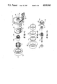
- FIG. 1 is an exploded view of the spindle motor herein;
- FIG. 2 is an exploded view of the elements of the rotor herein;
- FIG. 3 is an exploded view of the bearing cartridge assembly herein;
- FIG. 4 is a more detailed cross-sectional view of the bearing cartridge herein;
- FIG. 5 illustrates the windings of the coils on the stator herein and illustrates the spacing provided by the relatively wide slots between adjacent windings
- FIG. 6 is a plan view of the eight-pole rotor magnet of this invention.
- FIG. 7 illustrates the winding sequence of this invention
- FIG. 8 is a vertical sectional view of an alternative embodiment of a nine-slot, eight-pole motor mounted below the housing casing;
- FIG. 9 is a sectional plan view of the motor of FIG. 8 showing the location of the windings
- FIGS. 10A, B and C illustrate an axial gap configuration nine-slot, eight-pole spindle motor designed in accordance with this invention.
- FIG. 11 is a vertical sectional view of an alternative embodiment of the motor shown in FIG. 4.
- the motor is adapted for mounting on a base casting 10 that has a printed circuit board 12 mounted thereon.
- the base casting 10 can be fastened to the base housing of a disc drive to permanently seat the spindle motor in the base of the housing; to this end, screw holes 14 are provided in the edge of the base casting 10.
- the spindle motor designed in accordance with this invention may be mounted directly in the base casting.
- This printed circuit board 12 is used to detect the instantaneous position of the rotor through Hall effect devices 20 (FIG. 4) mounted on the surface of the printed circuit board 21 directly below the path of rotation of the rotor.
- the printed circuit board is mounted on disc drive casting 10.
- the stator subassembly 24, details of which are shown in FIG. 3, includes a threaded portion 26 which is easily screwed into the mating threaded portion 28 of the base casting 10 inside the region carrying the printed circuit board.
- FIG. 3 it can be seen that the essential elements of the stator subassembly, described in greater detail with reference to the sectional view of FIG. 4, comprise the housing tower 30, which includes the threaded portion 26 on the base thereof, and a flange 32 that seats down against the base casting 10.
- FIG. 3 also shows the upper and lower ball bearings 34, 36 which are to fit over the upper and lower portions of the shaft 38 inside the tower portion 40 of the overall housing 24. Separation between the upper and lower ball bearings is maintained by the coil spring 42.
- the shaft 38 is seated in the base 10 and supports the disc carrying hub 52 at its upper end.
- the remaining elements of the overall assembly comprise a nine slot wound stator 50 which is fastened in place on the outside of the tower shaft 40, and a rotor hub 52.
- the stator assembly will be explained in greater detail with reference to FIGS. 4-5.
- the elements of the rotor hub are shown in exploded fashion in FIG. 2 and comprise the hub 54 to which the discs are mounted, and end ring 56 which fits within the hub, a return ring 58 and eight-pole magnet ring 60.
- the magnet 60 of the rotor is an eight-pole magnet designed in accordance with known techniques to provide in combination with the nine sections of the stator a highly efficient motor having low cogging torque and a highly efficient use of copper and steel in its construction.
- the motor shaft 38 is shown surrounded by the upper and lower bearings 34 and 36 which support the shaft 38 for rotation.
- a ground button 62 is provided on the end of this shaft to prevent static charge buildup.
- the hub is mounted on the upper end of shaft 38 at 63. As the stator coils 80 are selectively energized, the rotor 60 disc carrying and shaft 38 rotate at a constant speed as required in a disc drive.
- the upper ball bearing 34 which is an integral assembly includes a magnetic seal 64 as an integral part thereof. This is provided in order to concentrate the magnetic return path. Since the inner race 65 of the upper bearing rotates with the shaft, while the outer race 66 remains stationary, a magnetic fluid may be placed in a small channel 67 adjacent the outer shaft in order to concentrate the magnetic return path.
- the stator 50 is bonded to the outer surface of the housing tower 40 which surrounds shaft 38.
- the structure of the stator and its winding pattern appears clearly in FIGS. 6-7 and will be explained below.
- An insulator 74 is provided at the lower portion of the tower 40. It is mounted on flange 76 of the tower 40 adjacent the stator laminations 50 to eliminate possible shorting of the stator 50 against the steel material of the housing tower 40.
- FIG. 5 is a plan view of the stator showing the spatial arrangement of the windings 90A-I that form the stator 50.
- the windings 90 are wound around support forms 91 bonded to the upper portion of the housing as shown in FIG. 4.
- Each winding 90 is well separated from the next adjacent winding 90 by a relatively wide slot 92.
- This stator winding arrangement mounted on a stack facing a rotor 60 rotating outside the stack, the windings can be very easily assembled, resulting in a maximum efficient use of the copper in the windings.
- the rotor is shown in FIG. 6, and comprises eight poles 94, each identified by letters N, S which indicate the radial orientation of the poles.
- the winding sequence of this invention is shown in FIG. 7.
- the first phase, Phase A is connected using windings all connected in the clockwise direction, starting with any first pole which may be considered one, and then incorporating poles n+2 3) and (n+4)5.
- the next phase starts with pole 4 (or original pole n+3) and includes poles 6(n+5) and 8(n+7).
- the final phase includes poles 7(n+6) and 9(n+8) and to complete the sequence, pole 2(n+1).
- FIG 8. An alternative embodiment of a nine-slot, eight-pole configuration that incorporates the advantages of this invention is shown in FIG 8.
- the coils 110 are wound over spindle laminations 112 mounted below the base 114 of the disc drive housing.
- the rotor magnet 116 is radially aligned with the stator and forms an annulus rotating outside the stator.
- the annular magnet 116 is carried in a shallow, cup-shaped housing 118 whose inner portion is supported on flanges 120 of a rotating shaft 122.
- the shaft, supported on axially adjacent bearings 124, 126 extends up through the base casting 114 to carry the hub 128 which will have the discs for the disc drive mounted on its outer surface.
- FIG. 9 is a plan view of the disc drive of FIG. 8, especially intended to illustrate the spacing of the stepper coils 110A-I.
- the location of the printed circuit board 112 that carries the necessary control electronics to drive the spindle motor is also shown in this view as well as the location of the three Hall effect devices 114A,B,C, used to monitor the rotation of the motor.
- This figure also illustrates the manner in which the lead wires 120 which run to the spindle motor coils are brought into the coils as the rotor and stator coils. As also shown in FIG. 8, these wires 120 are lead up through the printed circuit board 112 to be brought past the rotor, and then dropped back down through an opening in the printed circuit board 112 adjacent to the stator coils and above the edge of the laminations in order to allow the wires to be connected to stator coils 110.
- FIG. 10A shows the stator for the motor, comprising nine generally triangular, or wedge shaped planar form windings 120A-I.
- the windings 120 are mounted on a winding support 122 surrounding a bore 124 which comprises an opening for the shaft.
- the eight-pole rotor magnet 126 which is a flat magnet with a bore 128 for mounting the magnet on the shaft, is shown in FIG. 10B.
- the magnet 126 and its steel return path disc 130 are shown mounted back to back in FIG. 10C.
- the rotor and stator are shown here mounted in parallel planes to minimize the height of this portion of the motor while maximizing the motor torque to be produced with the changing sequence of energization of the coil 120.
- FIG. 11 One final embodiment of a motor incorporating the nine-slot, eight-pole design is shown in FIG. 11.
- the shaft 130 is stationary.
- the shaft supports stator laminations 132 bonded to its outer surface and the stator windings 134.
- the windings are formed and the laminations shaped to provide the space coil structure especially clearly shown in FIG. 9 of a previous embodiment.
- the upper and lower ends of the shaft 130 have bearings 136, 138 attached thereto, with the disc drive support hub 140 rotating on the outer race 142, 144 of these bearings.
- the lower end generally indicated at 146 of the shaft is fixed in the base casting 148 of the disc drive housing.
- the hub 140 which supports the discs 150, 152, 154 has a flange 156 at the lower end thereof.
- the discs are captured between this flange 156 and a disc clamp 158 held in place by clamping bolts not shown inserted in threaded openings 160 in the top surface of the disc clamp.
- the spacing between vertically adjacent discs is fixed by spacers 156, 158.
- the interior surface of the aluminum hub carries an eight-pole magnet 162 and an annular steel plate 164 which forms the magnetic return path for the magnetic flux.
- the magnet and return path are carried in the hub in the region adjacent the stator to cause rotation of the hub width of the hub 140 with selective energization of the stator windings 134 as discussed above.
- the printed circuit board 166 carrying the motor electronics and the Hall devices 168 for detecting motor position are mounted on a flange 170 secured to the outer surface of the stationary shaft above the lower bearing 138.
- the wires to the coils and the Hall devices are lead up through the hollow center of the stationary shaft and connected to the stationary Hall devices and stator coils through an opening 172 leading from the hollow center to the outer surface of the shaft.
- spindle motors with high efficiency and low cogging torque.
Abstract
Description
Claims (21)
Priority Applications (6)
| Application Number | Priority Date | Filing Date | Title |
|---|---|---|---|
| US07/115,268 US4858044A (en) | 1987-05-04 | 1987-10-30 | Disc drive spindle motor with low cogging torque |
| AU15163/88A AU606940B2 (en) | 1987-05-04 | 1988-04-26 | Disc drive spindle motor with low cogging torque |
| EP88304000A EP0290226A3 (en) | 1987-05-04 | 1988-05-03 | Disc drive spindle motor with low cogging torque |
| CA000565734A CA1290380C (en) | 1987-05-04 | 1988-05-03 | Disc drive spindle motor with low cogging torque |
| KR1019880005186A KR0132424B1 (en) | 1987-05-04 | 1988-05-04 | Disc drive spindle motor with low cogging torque |
| JP63110303A JPS6419949A (en) | 1987-05-04 | 1988-05-06 | Disc drive spindle motor |
Applications Claiming Priority (2)
| Application Number | Priority Date | Filing Date | Title |
|---|---|---|---|
| US07/046,234 US4847712A (en) | 1987-05-04 | 1987-05-04 | Disc drive spindle motor with log cogging torque |
| US07/115,268 US4858044A (en) | 1987-05-04 | 1987-10-30 | Disc drive spindle motor with low cogging torque |
Related Parent Applications (1)
| Application Number | Title | Priority Date | Filing Date |
|---|---|---|---|
| US07/046,234 Continuation-In-Part US4847712A (en) | 1987-05-04 | 1987-05-04 | Disc drive spindle motor with log cogging torque |
Publications (1)
| Publication Number | Publication Date |
|---|---|
| US4858044A true US4858044A (en) | 1989-08-15 |
Family
ID=26723689
Family Applications (1)
| Application Number | Title | Priority Date | Filing Date |
|---|---|---|---|
| US07/115,268 Expired - Lifetime US4858044A (en) | 1987-05-04 | 1987-10-30 | Disc drive spindle motor with low cogging torque |
Country Status (6)
| Country | Link |
|---|---|
| US (1) | US4858044A (en) |
| EP (1) | EP0290226A3 (en) |
| JP (1) | JPS6419949A (en) |
| KR (1) | KR0132424B1 (en) |
| AU (1) | AU606940B2 (en) |
| CA (1) | CA1290380C (en) |
Cited By (29)
| Publication number | Priority date | Publication date | Assignee | Title |
|---|---|---|---|---|
| US4985792A (en) * | 1989-03-06 | 1991-01-15 | Seagate Technology, Inc. | Disk drive spindle motor with externally mounted flux concentrator ring |
| US5013947A (en) * | 1990-03-16 | 1991-05-07 | Russell Ide | Low-profile disk drive motor |
| US5160866A (en) * | 1989-02-22 | 1992-11-03 | Nippon Densan Corporation | Spindle motor |
| US5170086A (en) * | 1987-12-10 | 1992-12-08 | Papst Motoren Gmbh | Electric motor with toothed disk to secure stator core |
| US5291357A (en) * | 1990-06-29 | 1994-03-01 | Nippon Densan Corporation | Magnetic recording device having reduced electromagnetic interference |
| US5305163A (en) * | 1990-12-31 | 1994-04-19 | Seagate Technology, Inc. | Stationary angularly aligned stationary spindle shaft |
| WO1995015559A1 (en) * | 1993-12-03 | 1995-06-08 | Maxtor Corporation | Axial spindle motor for hard disk drive assembly |
| US5506458A (en) * | 1994-03-04 | 1996-04-09 | Quantum Corporation | Low cost permanent magnet disk spindle motor |
| US5530326A (en) * | 1993-07-19 | 1996-06-25 | Quantum Corporation | Brushless DC spindle motor startup control |
| US5569990A (en) * | 1995-03-31 | 1996-10-29 | Seagate Technology, Inc. | Detection of starting motor position in a brushless DC motor |
| US5606473A (en) * | 1993-11-02 | 1997-02-25 | Seagate Technology, Inc. | Unitary rigid and flexible circuit package for disk drives |
| US5606475A (en) * | 1992-10-12 | 1997-02-25 | Kabushiki Kaisha Sanyo Seiki Seisakusho | Magnetic disc drive motor including a fixed shaft having mounted thereon a lower bearing member with a portion for mounting a rotor |
| US5705868A (en) * | 1996-04-25 | 1998-01-06 | Seagate Technology, Inc. | Spindle motor connector having supported electrical leads |
| US5841252A (en) * | 1995-03-31 | 1998-11-24 | Seagate Technology, Inc. | Detection of starting motor position in a brushless DC motor |
| US5859745A (en) * | 1993-11-02 | 1999-01-12 | Seagate Technology, Inc. | Split ring mounting for disk drive spindle and actuator shafts |
| US5923105A (en) * | 1995-12-06 | 1999-07-13 | International Business Machines Corporation | Disk drive in-hub radial-gap spindle motor with coils generating axial fields |
| US6204996B1 (en) * | 1992-10-16 | 2001-03-20 | Seagate Technology Llc | Low profile spindle motor |
| US20020163281A1 (en) * | 2001-05-04 | 2002-11-07 | Menachem Rafaelof | Thin film motors |
| US6702592B1 (en) | 1999-12-03 | 2004-03-09 | Seagate Technology Llc | Printed circuit board assembly with secondary side rigid electrical pin to mate with compliant contact |
| US20050073270A1 (en) * | 2001-07-18 | 2005-04-07 | Daniel Prudham | Polyphase motor |
| US20070273238A1 (en) * | 2006-05-26 | 2007-11-29 | Nidec Corporation | Brushless motor |
| US20080247689A1 (en) * | 2007-04-06 | 2008-10-09 | Nidec Corporation | Motor |
| US20080290747A1 (en) * | 2007-05-21 | 2008-11-27 | Nidec Corporation | Motor |
| US20110176240A1 (en) * | 2010-01-19 | 2011-07-21 | Alphana Technology Co., Ltd. | disk drive device that rotates a disk |
| US20120067317A1 (en) * | 2010-09-18 | 2012-03-22 | Raymond Towne | Anti-cogging apparatus and methods for reducing cogging of rotating shaft |
| US9297302B2 (en) | 2010-09-18 | 2016-03-29 | Raymond Towne | Mechanical-based anti-cogging apparatuses and systems for applying an anti-cogging torque on a rotating shaft |
| US10236742B2 (en) | 2014-11-25 | 2019-03-19 | Black & Decker Inc. | Brushless motor for a power tool |
| US10328567B2 (en) | 2015-10-14 | 2019-06-25 | Black & Decker Inc. | Brushless motor system for power tools |
| US11632062B2 (en) | 2020-01-24 | 2023-04-18 | Toyota Motor Engineering & Manufacturing North America, Inc. | Electrostatically rotatable gear and gear set |
Families Citing this family (5)
| Publication number | Priority date | Publication date | Assignee | Title |
|---|---|---|---|---|
| US5006745A (en) * | 1988-08-03 | 1991-04-09 | Victor Company Of Japan, Ltd. | Polyphase direct current motor |
| EP0433037B1 (en) * | 1989-12-15 | 1995-02-01 | Seagate Technology International | Spindle motor and disk drive provided therewith |
| JPH0748935B2 (en) * | 1990-11-30 | 1995-05-24 | 日本ビクター株式会社 | Multi-phase DC motor |
| US5210474A (en) * | 1992-02-27 | 1993-05-11 | Quantum Corporation | Digital-analog driver for brushless D.C. spindle motor |
| JP2002281721A (en) * | 2001-03-22 | 2002-09-27 | Yaskawa Electric Corp | Permanent magnet synchronous motor |
Citations (7)
| Publication number | Priority date | Publication date | Assignee | Title |
|---|---|---|---|---|
| US4528485A (en) * | 1982-04-13 | 1985-07-09 | General Electric Company | Electronically commutated motor, method of operating such, control circuit, laundry machine and drive therefor |
| US4535276A (en) * | 1983-01-12 | 1985-08-13 | Matsushita Electric Industrial Co., Ltd. | Output circuit and brushless motor using the same |
| US4578606A (en) * | 1984-12-13 | 1986-03-25 | Buehler Products, Inc. | Brushless DC electric motor and tachogenerator assembly |
| US4605874A (en) * | 1984-06-12 | 1986-08-12 | Maghemite Inc. | Brushless D.C. dynamoelectric machine having ferrite material magnetic circuit |
| US4626727A (en) * | 1984-05-11 | 1986-12-02 | U.S. Philips Corporation | Flat, permanent magnet electric motor |
| US4633149A (en) * | 1985-09-10 | 1986-12-30 | Buehler Products, Inc. | Brushless DC motor |
| US4707645A (en) * | 1986-07-25 | 1987-11-17 | Shicoh Engineering Co., Ltd. | Single-phase brushless motor |
Family Cites Families (7)
| Publication number | Priority date | Publication date | Assignee | Title |
|---|---|---|---|---|
| JPS5499908A (en) * | 1978-01-23 | 1979-08-07 | Matsushita Electric Ind Co Ltd | Electric motor |
| DE7930964U1 (en) * | 1978-11-03 | 1984-10-04 | Papst-Motoren GmbH & Co KG, 7742 St Georgen | MAGNETIC DISK DRIVE |
| JPS57160357A (en) * | 1981-03-27 | 1982-10-02 | Hitachi Ltd | Two-phase generator-motor |
| JPS5846280B2 (en) * | 1981-11-09 | 1983-10-15 | 三井造船株式会社 | Coal hydrogenation and liquefaction method |
| DE3419814C1 (en) * | 1984-05-26 | 1985-11-28 | GMN Georg Müller Nürnberg GmbH, 8500 Nürnberg | Motor spindle for magnetic disk storage |
| US4847526A (en) * | 1985-07-11 | 1989-07-11 | Nippon Ferrofluidics Corporation | Variant-pole electric motor |
| AU6009286A (en) * | 1985-07-11 | 1987-01-15 | Nippon Ferrofluidics Corp. | Variant pole electric motor |
-
1987
- 1987-10-30 US US07/115,268 patent/US4858044A/en not_active Expired - Lifetime
-
1988
- 1988-04-26 AU AU15163/88A patent/AU606940B2/en not_active Expired - Fee Related
- 1988-05-03 CA CA000565734A patent/CA1290380C/en not_active Expired - Fee Related
- 1988-05-03 EP EP88304000A patent/EP0290226A3/en not_active Withdrawn
- 1988-05-04 KR KR1019880005186A patent/KR0132424B1/en not_active IP Right Cessation
- 1988-05-06 JP JP63110303A patent/JPS6419949A/en active Pending
Patent Citations (7)
| Publication number | Priority date | Publication date | Assignee | Title |
|---|---|---|---|---|
| US4528485A (en) * | 1982-04-13 | 1985-07-09 | General Electric Company | Electronically commutated motor, method of operating such, control circuit, laundry machine and drive therefor |
| US4535276A (en) * | 1983-01-12 | 1985-08-13 | Matsushita Electric Industrial Co., Ltd. | Output circuit and brushless motor using the same |
| US4626727A (en) * | 1984-05-11 | 1986-12-02 | U.S. Philips Corporation | Flat, permanent magnet electric motor |
| US4605874A (en) * | 1984-06-12 | 1986-08-12 | Maghemite Inc. | Brushless D.C. dynamoelectric machine having ferrite material magnetic circuit |
| US4578606A (en) * | 1984-12-13 | 1986-03-25 | Buehler Products, Inc. | Brushless DC electric motor and tachogenerator assembly |
| US4633149A (en) * | 1985-09-10 | 1986-12-30 | Buehler Products, Inc. | Brushless DC motor |
| US4707645A (en) * | 1986-07-25 | 1987-11-17 | Shicoh Engineering Co., Ltd. | Single-phase brushless motor |
Cited By (45)
| Publication number | Priority date | Publication date | Assignee | Title |
|---|---|---|---|---|
| US5170086A (en) * | 1987-12-10 | 1992-12-08 | Papst Motoren Gmbh | Electric motor with toothed disk to secure stator core |
| US5160866A (en) * | 1989-02-22 | 1992-11-03 | Nippon Densan Corporation | Spindle motor |
| USRE36086E (en) * | 1989-02-22 | 1999-02-09 | Nidec Corporation | Spindle motor |
| US4985792A (en) * | 1989-03-06 | 1991-01-15 | Seagate Technology, Inc. | Disk drive spindle motor with externally mounted flux concentrator ring |
| US5013947A (en) * | 1990-03-16 | 1991-05-07 | Russell Ide | Low-profile disk drive motor |
| US5291357A (en) * | 1990-06-29 | 1994-03-01 | Nippon Densan Corporation | Magnetic recording device having reduced electromagnetic interference |
| US5305163A (en) * | 1990-12-31 | 1994-04-19 | Seagate Technology, Inc. | Stationary angularly aligned stationary spindle shaft |
| US5606475A (en) * | 1992-10-12 | 1997-02-25 | Kabushiki Kaisha Sanyo Seiki Seisakusho | Magnetic disc drive motor including a fixed shaft having mounted thereon a lower bearing member with a portion for mounting a rotor |
| US6204996B1 (en) * | 1992-10-16 | 2001-03-20 | Seagate Technology Llc | Low profile spindle motor |
| US5530326A (en) * | 1993-07-19 | 1996-06-25 | Quantum Corporation | Brushless DC spindle motor startup control |
| US5606473A (en) * | 1993-11-02 | 1997-02-25 | Seagate Technology, Inc. | Unitary rigid and flexible circuit package for disk drives |
| US5859745A (en) * | 1993-11-02 | 1999-01-12 | Seagate Technology, Inc. | Split ring mounting for disk drive spindle and actuator shafts |
| US5982578A (en) * | 1993-11-02 | 1999-11-09 | Seagate Technology, Inc. | Disk drive housing with recess for circuit panel |
| US5726829A (en) * | 1993-12-03 | 1998-03-10 | Maxtor Corporation | Axial spindle motor for hard disk drive assembly |
| WO1995015559A1 (en) * | 1993-12-03 | 1995-06-08 | Maxtor Corporation | Axial spindle motor for hard disk drive assembly |
| US5506458A (en) * | 1994-03-04 | 1996-04-09 | Quantum Corporation | Low cost permanent magnet disk spindle motor |
| US5569990A (en) * | 1995-03-31 | 1996-10-29 | Seagate Technology, Inc. | Detection of starting motor position in a brushless DC motor |
| US5841252A (en) * | 1995-03-31 | 1998-11-24 | Seagate Technology, Inc. | Detection of starting motor position in a brushless DC motor |
| US5923105A (en) * | 1995-12-06 | 1999-07-13 | International Business Machines Corporation | Disk drive in-hub radial-gap spindle motor with coils generating axial fields |
| US5705868A (en) * | 1996-04-25 | 1998-01-06 | Seagate Technology, Inc. | Spindle motor connector having supported electrical leads |
| US6702592B1 (en) | 1999-12-03 | 2004-03-09 | Seagate Technology Llc | Printed circuit board assembly with secondary side rigid electrical pin to mate with compliant contact |
| US20020163281A1 (en) * | 2001-05-04 | 2002-11-07 | Menachem Rafaelof | Thin film motors |
| US20050073270A1 (en) * | 2001-07-18 | 2005-04-07 | Daniel Prudham | Polyphase motor |
| US7466092B2 (en) * | 2001-07-18 | 2008-12-16 | Societe Industrielle De Soncebox, S.A. | Polyphase motor |
| US20070273238A1 (en) * | 2006-05-26 | 2007-11-29 | Nidec Corporation | Brushless motor |
| US7550884B2 (en) * | 2006-05-26 | 2009-06-23 | Nidec Corporation | Brushless motor |
| US20080247689A1 (en) * | 2007-04-06 | 2008-10-09 | Nidec Corporation | Motor |
| US20080290747A1 (en) * | 2007-05-21 | 2008-11-27 | Nidec Corporation | Motor |
| US7944103B2 (en) | 2007-05-21 | 2011-05-17 | Nidec Corporation | Motor |
| US20110176240A1 (en) * | 2010-01-19 | 2011-07-21 | Alphana Technology Co., Ltd. | disk drive device that rotates a disk |
| US8416523B2 (en) * | 2010-01-19 | 2013-04-09 | Alphana Technology Co., Ltd. | Disk drive device with versatile shaped core for rotating a disk |
| US20120067317A1 (en) * | 2010-09-18 | 2012-03-22 | Raymond Towne | Anti-cogging apparatus and methods for reducing cogging of rotating shaft |
| US8701615B2 (en) * | 2010-09-18 | 2014-04-22 | Raymond A. Towne, III | Anti-cogging apparatus and methods for reducing cogging of rotating shaft |
| US9447728B2 (en) | 2010-09-18 | 2016-09-20 | Raymond Towne | Magnet-based anti-cogging apparatuses and systems for applying an anti-cogging torque on a rotating shaft |
| US9297302B2 (en) | 2010-09-18 | 2016-03-29 | Raymond Towne | Mechanical-based anti-cogging apparatuses and systems for applying an anti-cogging torque on a rotating shaft |
| US9316284B2 (en) | 2010-09-18 | 2016-04-19 | Raymond Towne | Anti-cogging apparatus and methods for reducing cogging of rotating shaft |
| CN103842627A (en) * | 2011-09-16 | 2014-06-04 | 雷蒙德·A·汤 | Anti-cogging apparatus and methods for reducing cogging of rotating shaft |
| US10236742B2 (en) | 2014-11-25 | 2019-03-19 | Black & Decker Inc. | Brushless motor for a power tool |
| US10523081B2 (en) | 2014-11-25 | 2019-12-31 | Black & Decker Inc. | Brushless motor for a power tool |
| US10328567B2 (en) | 2015-10-14 | 2019-06-25 | Black & Decker Inc. | Brushless motor system for power tools |
| US10328566B2 (en) | 2015-10-14 | 2019-06-25 | Black & Decker Inc. | Brushless motor system for power tools |
| US10500708B2 (en) | 2015-10-14 | 2019-12-10 | Black & Decker Inc. | Power tool |
| US10786894B2 (en) | 2015-10-14 | 2020-09-29 | Black & Decker Inc. | Brushless motor system for power tools |
| US11951603B2 (en) | 2015-10-14 | 2024-04-09 | Black & Decker Inc. | Brushless motor system for power tools |
| US11632062B2 (en) | 2020-01-24 | 2023-04-18 | Toyota Motor Engineering & Manufacturing North America, Inc. | Electrostatically rotatable gear and gear set |
Also Published As
| Publication number | Publication date |
|---|---|
| JPS6419949A (en) | 1989-01-24 |
| KR880014712A (en) | 1988-12-24 |
| AU606940B2 (en) | 1991-02-21 |
| AU1516388A (en) | 1988-11-10 |
| EP0290226A2 (en) | 1988-11-09 |
| EP0290226A3 (en) | 1989-10-18 |
| CA1290380C (en) | 1991-10-08 |
| KR0132424B1 (en) | 1998-04-20 |
Similar Documents
| Publication | Publication Date | Title |
|---|---|---|
| US4858044A (en) | Disc drive spindle motor with low cogging torque | |
| US4847712A (en) | Disc drive spindle motor with log cogging torque | |
| US5783893A (en) | Multiple stator, single shaft electric machine | |
| EP0223093B1 (en) | Brushless motor | |
| US4905110A (en) | Disk drive spindle motor | |
| CA1133127A (en) | Disc recorder with brushless dc motor drive | |
| US5675196A (en) | High speed ten pole/twelve slot D.C. brushless motor with minimized net radial force and low cogging torque | |
| US5633545A (en) | Disk drive in-hub radial-gap spindle motor with coils generating axial fields | |
| US5710476A (en) | Armature design for an axial-gap rotary electric machine | |
| US5552650A (en) | Disk storage device with motor with axially deep flange | |
| US5739614A (en) | Two-phase unipolar driving brushless DC motor | |
| US5742450A (en) | Disk drive spindle motor with radial gap and field generating coils interconnected by ring flux guide | |
| US5057731A (en) | Simplified spindle motor for disc drive | |
| US5923110A (en) | Spindle motor for optical disc drives | |
| EP0393266B1 (en) | Improved spindle motor for a disc drive | |
| USRE35702E (en) | Compact motor mount for information storage devices | |
| EP0723328B1 (en) | An electric motor | |
| KR20210076824A (en) | Axial field flow rotating machine | |
| JPH09322452A (en) | Dynamo-electric machine | |
| EP0402179B1 (en) | An electric motor | |
| JP2710163B2 (en) | Spindle motor used for disk drive | |
| GB2209438A (en) | Brush gear for an electric motor | |
| JPS58159653A (en) | Brushless motor | |
| GB2213653A (en) | A permanent magnet D.C. motor with flux concentrator | |
| JP2004208381A (en) | Brushless motor |
Legal Events
| Date | Code | Title | Description |
|---|---|---|---|
| AS | Assignment |
Owner name: SEAGATE TECHNOLOGY, SCOTTS VALLEY, CA A CORP. OF C Free format text: ASSIGNMENT OF ASSIGNORS INTEREST.;ASSIGNOR:CRAPO, ALAN D.;REEL/FRAME:004785/0287 Effective date: 19871029 Owner name: SEAGATE TECHNOLOGY, SCOTTS VALLEY, CA A CORP. OF,C Free format text: ASSIGNMENT OF ASSIGNORS INTEREST;ASSIGNOR:CRAPO, ALAN D.;REEL/FRAME:004785/0287 Effective date: 19871029 |
|
| STCF | Information on status: patent grant |
Free format text: PATENTED CASE |
|
| AS | Assignment |
Owner name: SEAGATE TECHNOLOGY, INC., A CORP. OF DE, DELAWARE Free format text: MERGER;ASSIGNOR:SEAGATE TECHNOLOGY (MERGED INTO);REEL/FRAME:005195/0838 Effective date: 19870204 |
|
| AS | Assignment |
Owner name: SECURITY PACIFIC NATIONAL BANK, NEW YORK Free format text: SECURITY INTEREST;ASSIGNOR:SEAGATE TECHNOLOGY, INC.;REEL/FRAME:005221/0294 Effective date: 19890929 |
|
| FPAY | Fee payment |
Year of fee payment: 4 |
|
| AS | Assignment |
Owner name: SEAGATE TECHNOLOGY, INC., CALIFORNIA Free format text: RELEASED BY SECURED PARTY;ASSIGNOR:BANKAMERICA CORPORATION;REEL/FRAME:006496/0048 Effective date: 19920421 |
|
| FEPP | Fee payment procedure |
Free format text: PAYOR NUMBER ASSIGNED (ORIGINAL EVENT CODE: ASPN); ENTITY STATUS OF PATENT OWNER: LARGE ENTITY |
|
| FPAY | Fee payment |
Year of fee payment: 8 |
|
| AS | Assignment |
Owner name: SEAGATE TECHNOLOGY LLC, CALIFORNIA Free format text: ASSIGNMENT OF ASSIGNORS INTEREST;ASSIGNOR:SEAGATE TECHNOLOGY, INC.;REEL/FRAME:011077/0319 Effective date: 20000728 |
|
| FPAY | Fee payment |
Year of fee payment: 12 |
|
| AS | Assignment |
Owner name: THE CHASE MANHATTAN BANK, AS COLLATERAL AGENT, NEW Free format text: SECURITY AGREEMENT;ASSIGNOR:SEAGATE TECHNOLOGY LLC;REEL/FRAME:011461/0001 Effective date: 20001122 |
|
| AS | Assignment |
Owner name: JPMORGAN CHASE BANK, AS COLLATERAL AGENT, NEW YORK Free format text: SECURITY AGREEMENT;ASSIGNOR:SEAGATE TECHNOLOGY LLC;REEL/FRAME:013177/0001 Effective date: 20020513 Owner name: JPMORGAN CHASE BANK, AS COLLATERAL AGENT,NEW YORK Free format text: SECURITY AGREEMENT;ASSIGNOR:SEAGATE TECHNOLOGY LLC;REEL/FRAME:013177/0001 Effective date: 20020513 |
|
| AS | Assignment |
Owner name: SEAGATE TECHNOLOGY LLC, CALIFORNIA Free format text: RELEASE OF SECURITY INTERESTS IN PATENT RIGHTS;ASSIGNOR:JPMORGAN CHASE BANK, N.A. (FORMERLY KNOWN AS THE CHASE MANHATTAN BANK AND JPMORGAN CHASE BANK), AS ADMINISTRATIVE AGENT;REEL/FRAME:016926/0821 Effective date: 20051130 |