US4842386A - Variable focal length objective - Google Patents
Variable focal length objective Download PDFInfo
- Publication number
- US4842386A US4842386A US06/877,102 US87710286A US4842386A US 4842386 A US4842386 A US 4842386A US 87710286 A US87710286 A US 87710286A US 4842386 A US4842386 A US 4842386A
- Authority
- US
- United States
- Prior art keywords
- lens
- gradient
- index
- lens unit
- sup
- Prior art date
- Legal status (The legal status is an assumption and is not a legal conclusion. Google has not performed a legal analysis and makes no representation as to the accuracy of the status listed.)
- Expired - Lifetime
Links
Images

Classifications
-
- G—PHYSICS
- G02—OPTICS
- G02B—OPTICAL ELEMENTS, SYSTEMS OR APPARATUS
- G02B15/00—Optical objectives with means for varying the magnification
- G02B15/14—Optical objectives with means for varying the magnification by axial movement of one or more lenses or groups of lenses relative to the image plane for continuously varying the equivalent focal length of the objective
- G02B15/144—Optical objectives with means for varying the magnification by axial movement of one or more lenses or groups of lenses relative to the image plane for continuously varying the equivalent focal length of the objective having four groups only
- G02B15/1441—Optical objectives with means for varying the magnification by axial movement of one or more lenses or groups of lenses relative to the image plane for continuously varying the equivalent focal length of the objective having four groups only the first group being positive
- G02B15/144113—Optical objectives with means for varying the magnification by axial movement of one or more lenses or groups of lenses relative to the image plane for continuously varying the equivalent focal length of the objective having four groups only the first group being positive arranged +-++
Definitions
- This invention relates to variable focal length objectives, and more particularly to such objective which has a plurality of lens units with the separation between the first and second lens units being varied to vary the focal length of the entire system.
- the aberration problem of the variable focal length objective especially the zoom lens that varies its focal length continuously, must be solved, besides the good correction of aberrations in the standard setting, for as far minimized variation with zooming of the aberrations as possible.
- all the lens units are required to be at least individually corrected well for spherical aberration, coma and astigmatism in each unit. It has, therefore, been the prior art practice that each lens unit is made up by using several lens elements.
- the type of zoom lens comprising a plurality of lens units of which the first and second counting from the front are respectively positive and negative in power and the separation between the first and second lens units
- its bulk and size can be reduced, speaking in the concept of Gauss theory, either by strengthening the power of each lens unit, or by shortening the intervals between the principal points of the successive two of the lens units.
- the method of strengthening the power of each lens unit may also be employed.
- the increase in the power of the lens unit calls for an increase in the number of constituent lens elements in order to achieve good stability of aberration correction over the entire zooming range. This may otherwise be achieved by increasing the power per one lens element with its surface curvatures being strengthened. To allow for the minimum acceptable edge thickness of every lens element, the central thickness of the positive lens and the axial air separation between the adjacent concave surfaces are caused to become very large. In either case, therefore, the physical length of each of the lens units increases. Also since the principal point interval has to be increased, the optical total length of the entire system can no longer be shortened. Such an increase of the length of the lens unit gives rise to another problem that as the space in which the lens unit movable for zooming makes excursion becomes small, a desired increase of the zoom ratio can no longer be achieved.
- the diameter of the first or front lens unit must be increased.
- the use of any of the prior known methods because of effecting the result of such a vicious cycle, could not filfill both requirements of achieving a much-desired reduction of the bulk and size of the zoom lens and of achieving a much desired increase of the zoom ratio while preserving good stability of aberration correction throughout the entire zooming range.
- An object of the present invention is to eliminate the above-described drawbacks of the prior art, and to provide a variable focal length objective of extended range with a lessened total number of lens elements while still permitting good stability of aberration correction to be achieved throughout the zooming range.
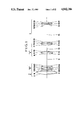
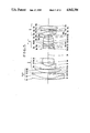
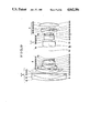
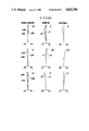
- FIGS. 1 to 11 are longitudinal section views of six examples of specific zoom lenses of the invention.
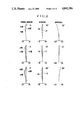
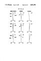
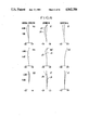
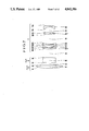
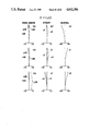
- FIGS. 2 to 12 are graphic representations of the aberrations of the first to the sixth lenses respectively.
- the present invention is applied to the variable focal length objective comprising a plurality of lens units of which the first and second counting from front are a positive lens unit and a negative lens unit respectively, and in which when varying the image magnification, the air separation between the first and second lens units is varied.
- a feature of the invention in such objective is that at least one of the plurality of lens units is included with at least one gradient-index lens having a refractive index distribution over the radius given by the expression:
- N 0 is the refractive index on the optical axis
- N 1 , N 2 , N 3 , . . . are constants, and is made with a refractive power ⁇ G satisfying the following conditions:
- the gradient-index lens herein used has a distribution of refractive indices along the radial direction of the lens, or so-called radial gradient of refractive index.
- a gradient-index lens is introduced to that lens unit which contributes to variation of the image magnification, or, in the usual zoom lens concept, the variator, or to that lens unit which contributes to compensate for the image shift, or, in the usual zoom lens concept, the compensator, it becomes possible to realize a variable focal length objective in which the bulk and size and weight are reduced in such a manner that a good stability of aberration correction over the extended range of variation of the focal length is achieved.
- the radial gradient-index lens differs from the ordinary lens of homogeneous material in that its interior has a converging action (hereinafter referred to as "positive transition of power”), or a diverging action (hereinafter referred to as "negative transition of power"). Further since a refractive index pattern appears from the lens surface, the refracting action of that surface on the rays of light also becomes different from that of the usual lens.
- D is the axial thickness of the lens.
- the aberration coefficients of the gradient-index lens are grouped to three sets of terms: (A) the terms of refraction arising when it is assumed to be a sphare of homogeneous medium are exposed by the formulae (4) to (8); (B) the terms of refraction due to the refractive index distribution over the surface of the gradient-index lens are exposed by the formulae (9) to (13); and (C) the terms of aberrations ascribable to the power of gradient of the medium of the gradient-index lens (hereinafter referred to as the "terms of gradient”) are expressed by the formulae (14) to (18). ##EQU1##
- N 1 For the distribution coefficient N 1 is of positive sign, on the other hand, when that surface is convex, ⁇ in ⁇ 0, so that the value of h 4 ⁇ in is positive. Hence the spherical aberration is produced in direction to under-correction. When that surface is concave, ⁇ in ⁇ 0, so that the value h 4 ⁇ in is negative. Hence the spherical aberration is produced in direction to over-correction.
- the term of the gradient for spherical aberration given by the expression of the equation (14) is of the very complicated form including terms of integrations. But, in the case of the radial type of gradient-index lens, N 0 , N 1 and N 2 when to integrate with respect to X or the axial direction can be treated as constants. Further, on assumption that the ray of light travelling in interior of the gradient-index lens does not largely change its height h or h, the equation (14) can be simplified to and approximated by ##EQU2##
- the term of gradient for the spherical aberration of the gradient-index lens has an important parameter as a function of the value of the distribution coefficient N 2 of the equation (1).
- the term of gradient for the spherical aberration can be controlled. For example, when N 2 >0, the spherical aberration is produced in direction to over-correction. For N 2 ⁇ 0, the spherical aberration is produced in direction to under-correction.
- the present invention sets forth the conditions under which the third-order aberrations of the gradient-index lens in terms of refraction and gradient of the above-described refractive index distribution cancel out each other for a higher degree of correction.
- the simple expression of these conditions is of the above-described form of the inequalities (2) and (3).
- the combination of these inequalities (2) and (3) means that the direction of production of the aberrations ascribable to the refractive index pattern on that surface of the gradient-index lens which has a stronger curvature than the other has is made opposite to the direction of production of the aberrations ascribable to the gradient of refractive index.
- the lens unit is of negative power: ⁇ G ⁇ 0
- the choosing of which sign to determine the coefficients N 1 and N 2 of the equation for the refractive index distribution of the gradient-index lens is made controlled in accordance with the critical conditions set forth above, when a higher degree of aberration correction is obtained.
- the radial type gradient-index lens in the invention must be taken that the radial gradient of refractive index is dominant on the performance of the lens itself. Therefore, regardless of the inclusion of another or longitudinal gradient of refractive index, if its effect is far weaker than that of the radial type, it should be understood that it falls within the scope and spirit of the invention.
- FIG. 1 in longitudinal section view illustrates the construction and arrangement of the elements of an example of a specific zoom lens according to the present invention
- FIG. 2 shows its aberrations.
- the first lens unit A is of positive power and is held stationary during zooming.
- the second lens unit B is of negative power and axially moves with zooming to contribute to variation of the image magnification
- the third lens unit C is of positive power and also axially moves with zooming to compensate for the image shift.
- the fourth lens unit D of positive power remains stationary during zooming.
- the positive first lens unit A is constructed in the form of a singlet defined by surfaces R 1 and R 2 and having a radial gradient of refractive index defined by the equation (1) where the coefficients N 1 and N 2 take the signs: N 1 ⁇ 0, and N 2 ⁇ 0.
- the above-defined gradient-index lens unlike the usual lens of homogeneous medium, gives a converging function at the medium as it has a positive transition of power.
- the aberrations are, therefore, primarily reduced remarkably.
- the use of the convex form in the positive first lens unit in combination with such a gradient of refractive index as to give a positive transition of power as in this zoom lens is advantageous at correcting spherical aberrations in the telephoto positions.
- Other aberrations for example, coma and astigmatism, can be also well corrected.
- the numerical data in accordance with which the zoom lens of FIG. 1 can be constructed are given in Tables 1-1 to 1-3 for the focal length f of the entire system, F-number FNO, the image angle 2 ⁇ , the radii of curvature, R, the axial thicknesses or air separations, D, and the refractive indices, N, and Abbe numbers, ⁇ , of the glasses of the lens elements with the subscripts numbered consecutively from front to rear, along with the values for the spectral d- and g-lines of the refractive index distribution coefficients N 0 to N 4 .
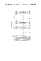
- FIG. 3 illustrates another specific zoom lens of the invention whose aberrations are shown in FIG. 4.
- the symbols in these figures have the same meanings as those in FIGS. 1 and 2.
- the zoom lens comprises, from front to rear, a positive first lens unit A which is held stationary during zooming, a negative second lens unit B which axially moves with zooming to contribute to variation of the image magnification, a positive third lens unit C which axially moves with zooming to compensate for the image shift, and a positive fourth lens unit D which remains stationary during zooming.
- the second lens unit B usually called the variator, is constructed with a gradient-index lens of the radial type with the surfaces R 6 and R 7 .
- the gradient-index lens is made of a gradient of refractive index defined by the equation (1) where the coefficients N 1 and N 2 are of opposite sign such that N 1 >0, and N 2 ⁇ 0.
- the above-defined gradient-index lens unlike the usual lens of homogeneous medium, gives a diverging function at its medium, and has a negative transition of power.
- ⁇ II denote the required power of the negative second lens unit B and D the thickness of the gradient-index lens
- ⁇ II denotes the required power of the negative second lens unit B and D the thickness of the gradient-index lens
- the gradient-index lens should be made with a gradient of refractive index of N 1 >0.
- the negative power of the lens unit B is partly borne by the term of gradient of the gradient-index lens.
- the negative second lens unit B can be constructed with one lens whose surfaces both are weak in curvature. Therefore, the zoom lens is fundamentally corrected to minimums of aberrations produced.
- the second lens unit B is constructed in the form of a bi-concave lens having a gradient of refractive index for the negative transition of power
- the spherical aberration in the telephoto positions can be advantageously corrected.
- other various aberrations for example, coma and astigmatism, can also be corrected well. This permits only one gradient-index lens to suffice for constituting the negative second lens unit.
- both surfaces of the aforesaid gradient-index lens of the negative second lens unit B are concave, and the coefficient N 1 in the equation for the gradient of refractive index is made N 1 >0, so that the third-order spherical aberration in terms of refraction at the concave surface is largely over-corrected in the telephoto positions.
- a possibility of taking a balance is provided.
- the spherical aberration can be corrected by controlling the terms of the gradient and refraction for the third-order aberration.
- the coma and astisgmatism can be corrected.
- the negative second lens unit B is constructed by using three lens elements and that the spherical aberration is corrected by the cemented surface of the cemented lens, it is in the zoom lens of the invention that despite the negative second lens unit B is constructed by using only one lens element, the spherical aberration can be well corrected.
- the Petzval sum can be corrected when the gradient-index lens of the negative second lens unit B is made of the gradient of refractive index that satisfies the inequality of condition (2), or the gradient of refractive index of N 1 >0 as in the zoom lens of FIG. 3.
- ⁇ denote the power owing to the converging or diverging effect of the medium of the gradient-index lens referred to the normalized focal length of the entire system to unity
- N 0 the basic refractive index
- the variator of the spherical system produces a Petzval sum of -1.25 to 1.3 in contrast to the negative second lens unit B as the variator of FIG. 3 which has a Petzval sum of -1.025 from the reason described above.
- the power of the zoom section may be strengthened or the telephoto ratio of the relay section may be reduced in order to shorten the optical total length of the entire system as compared with the spherical system. That is, the largest drawback of the conventional method for shortening the total length by strengthening the power of the zoom section, or by reducing the telephoto ratio of the relay section was that the Petzval sum became too large in the negative sense to be corrected. In the zoom lens of the invention, however, the variator produces a smaller Petzval sum in the negative sense, thus increasing the possibility of shortening the optical total length of the entire system by the above-described method.
- the telephoto ratio of the relay section comprised of the positive fourth lens unit D is reduced so that the ratio of the total length of the entire system of 254.8 mm to the longest focal length of the entire ratio, or the telephoto ratio of the entire system can be reduced to a very small value of 0.836. Further, by the room for freedom created in the Petzval sum, the power of the positive first lens of the surfaces R 11 and R 12 in the positive fourth lens unit D is made higher to permit a higher degree of spherical aberration correction to be achieved.
- the variator of the zoom lens is constructed with three to five lens elements of strong power, and the tolerances for the thicknesses of the lens elements, the air spacings and the decentering of the lens elements from the common axis must be very rigorous. But, now that it can be constructed with only one element as in the zoom lens of the invention, the assembly and the adjusting operation becomes extremely easy.
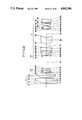
- FIG. 5 is a longitudinal section view illustrating another specific zoom lens of the invention, and FIG. 6 shows its aberrations.
- the symbols in these figures have the same meanings as in the foregoing examples.
- the zoom lens comprises, from front to rear, a positive first lens unit A which axially moves with zooming to contribute to variation of the image magnification, a negative second lens unit B which is held stationary during zooming, a positive third lens unit C which axially moves with zooming to contribute to a variation of the image magnification and also to compensate for the image shift, and a positive fourth lens unit D which remains stationary during zooming.
- the negative second lens unit B is constructed with a first radial gradient-index lens having surfaces R 6 and R 7 and a second radial gradient-index lens having surfaces R 8 and R 9 . Since, in this zoom lens, the negative second lens unit which is most sensitive to decentering is held stationary, it becomes possible to improve the assembly accuracy.
- the above-described two gradient-index lenses unlike the usual lens, have diverging actions at the interiors thereof, providing a negative transition power.
- the first gradient-index lens R 6 , R 7 has its rear surface R 7 made of a stronger concave curvature.
- This concave surface R 7 in combination with N 1 >0 produce over-corrected third-order spherical aberration in terms of refraction in the telephoto positions.
- the term of refraction for third-order spherical aberration, the term of gradient for third-order spherical aberration and the term of refraction for fifth-order spherical aberration allow the spherical aberrations to be balanced out, thus making it possible to correct the spherical aberration for a higher grade of imagery as the coma and astigmatism also can be well corrected in a similar manner.
- the zoom lens of FIG. 5 can be constructed in accordance with the numerical data given in Tables 3-1 to 3-3 below.
- This zoom lens comprises, from front to rear, a positive first lens unit A which axially moves with zooming, a negative second lens unit B which axially moves with zooming to contribute to variation of the image magnification, and positive third lens unit C which remains stationary during zooming.
- the positive first lens unit A consists of a radial gradient-index lens having surfaces R 1 and R 2 .
- the negative second lens unit B consists of a radial gradient-index lens having surfaces R 3 and R 4 front part of the third lens unit C includes a radial gradient lens of bi-convex form having surfaces R 5 and R 6 at the frontmost position, followed rearwardly after a very short spacing by an axial gradient-index lens of bi-convex form having surfaces R 7 and R 8 , and a rear part includes a radial gradient-index lens of convex form having surfaces R 10 and R 11 .
- the positive first lens unit is constructed in the form of a convex lens, and is made with such a gradient of refractive index that a positive transition power is produced as in the zoom lens of the invention, an advantage of correcting spherical aberration in the telephoto positions is produced. And, because other various aberrations can be well corrected, it has been made possible that only one lens element having the gradient of refractive index sufficies for contructing the positive first lens unit A.
- the radial gradient-index lens having the negative transition power in the negative second lens unit B because the negative transition power of the interior thereof can partly bear the power of the lens unit B, enables the curvature of the surfaces of the lens to be weakened with an advantage of correcting spherical aberration and Petzval sum.
- the negative lens unit B which would otherwise be made of homogeneous material only would produce a Petzval sum of -1.45 to -1.6 referred to the normalized focal length of the entire system to unity. But, in the zoom lens of the invention, as it is constructed with the radial gradient-index lens, the Petzval sum is reduced to a very small value of -1.06.
- the adoption of the gradient-index lens as the second lens unit B enables the Petzval sum to be suppressed.
- the third lens unit C is divided into the front and rear parts spaced apart by a longest distance D 9 in that lens unit.
- a gradient-index lens of bi-convex form As the frontmost lens in the front part use is made of a gradient-index lens of bi-convex form.
- a gradient-index lens which is also of bi-convex form As the frontmost lens in the rear part also, use is made of a gradient-index lens which is also of bi-convex form.
- the first-named and second-named gradient-index lenses have positive and negative transition powers respectively, and their gradients of refractive index are formed so as to satisfy the inequalities (2) and (3).
- the spherical aberration and coma of the front part and the spherical aberration, curvature of field and distortion of the rear part which would usually by deteriorated when the powers of the front and rear parts are strengthened in order to achieve a shortening of the entire system, are made possible to correct well.
- the above-described gradient-index lens unlike the usual lens of homogeneous medium, has a converging action even at its medium, getting a positive transition power.
- the fifth-order spherical aberration in terms of refraction is over-corrected.
- the third-order spherical aberrations in terms of refraction and gradient and the fifth order spherical aberration in terms of refraction are balanced out with one another to achieve a higher degree of correction of spherical aberration.
- higher degrees of correction of coma and astigmatism can be obtained.
- the refractive power of the negative second lens unit B be denoted by ⁇ II and the thickness of the aforesaid gradient-index lens by D
- the refractive power of the negative second lens unit B can be denoted by ⁇ II and the thickness of the aforesaid gradient-index lens by D
- the negative second lens unit can be constructed by using one lens element whose both surfaces are of weaker curvature.
- the fifth-order spherical aberration in terms of refraction is under-corrected. Therefore, the third-order spherical aberrations in terms of gradient and refraction and the fifth-order spherical aberration in terms of refraction are balanced out with one another to achieve a higher degree of correction of spherical aberration. In a similar manner, higher degrees of corection of coma and astigmatism can be achieved.
- the negative second lens unit B is constructed with three lens elements, and the spherical aberration is corrected by the cemented surface of them.
- the various aberrations can be corrected.
- the spherical aberration can be well corrected, and other aberrations for example, coma and astigmatism, can also be well corrected. Therefore, the total length can be shortened by strengthening the power of the front part. That is, regarding the correction of spherical aberration, for the gradient of refractive index is made of N 1 ⁇ 0, the third-order spherical aberration in terms of refraction is over-corrected in the telephoto positions, and the spherical aberration in terms of gradient is produced as opposed to that in terms of refraction to permit a balance to be taken.
- the gradient of refractive index is made of N 2 ⁇ 0
- the fifth-order spherical aberration in terms of refraction is over-corrected.
- the third-order spherical aberrations in terms of refraction and gradient and the fifth-order spherical aberration in terms of refraction are delicately balanced out with one another to permit a higher degree of correction of spherical aberration to be obtained. In a similar manner, higher degrees of correction of coma and astigmatism can also be obtained.
- the fifth-order spherical aberration in terms of refraction is under-corrected.
- the third-order spherical aberration and the fifth-order spherical aberration in terms of refraction are balanced out to achieve a higher degree of correction of spherical aberration. Also, higher degrees of correction of coma, astigmatism, and distortion can be obtained.
- the fourth example of the specific zoom lens can be constructed in accordance with the numerical data given in Tables 4-1 to 4-3.
- the gradient of refractive index N 4 (x) can be expressed by the following equation in terms of the distance x measured from the front vertex toward the rear in the direction parallel to the optical axis.
- N 0 is the refractive index at the front vertex
- N 1 , N 2 , N 3 , . . . are coefficients similarly to the radial type.
- This zoom lens comprises, from front to rear, a positive first lens unit A which axially moves with zooming to contribute to variation of the image magnification, a negative second lens unit B which is held stationary during zooming, a positive third lens unit C which axially moves with zooming to contribute to a variation of the image magnification and to compensate for the image shift, and a positive fourth lens unit D which remains stationary during zooming.
- the third lens unit C comprises, front from to rear, positive, negative and positive lenses, of which the first positive is a radial gradient-index lens having a positive transition power with the surfaces R 14 and R 15 , and the second positive is a radial gradient-index lens having a negative transition power with the surfaces R 18 and R 19 . Because, in this zoom lens, the position of the negative second lens unit B relative to the image plane does not change, this type is suited to facilitate simplification of the structure of the operating mechanism.
- the rays of light emerging from the negative second lens unit B are divergent on the positive first lens of the third lens unit C.
- the positive first or gradient-index lens has a positive transition power, for, as the positive power of that lens is so much strengthened, the principal point of the positive third lens unit C is brought to a more forward position, the interval between the principal points of the negative second and positive third lenses can be reduced, contributing to a shortening of the entire system.
- the use of another gradient-index lens as this lens allows for correcting particularly astigmatism.
- the positive third lens unit C in this kind of zoom lens is constructed with at least five lens elements.
- the invention on the other hand, only three lens elements suffice, contributing to a compactness of the entire system.
- Another advantage arising from the reduction of the number of lens elements is that the assembly and the adjusting operation become easier, making it possible to simplify the structure of the operating mechanism.
- the refractive power of the positive third lens unit C be denoted by ⁇ III and the thickness of the gradient-index lens by D
- the refractive power of the positive third lens unit C is partly borne by the term of gradient of that gradient-index lens.
- the zoom lens of FIG. 9 can be constructed in accordance with the numerical data given in Tables 5-1 to 5-3 below.
- This zoom lens comprises, from front to rear, a positive first lens unit A which is held stationary during zooming, a negative second lens unit B which axially moves with zooming to contribute to variation of the image magnification, a negative third lens unit C which axially moves with zooming to compensate for the image shift, and a positive fourth lens unit D which is held stationary during zooming.
- the fourth lens unit D is usually included with a positive lens for making afocal the arriving rays of divergence in passing therethrough at the front most position and a prism (not shown) as a beam splitter for the finder, and, in many cases, also with a diaphragm.
- the image plane is immediately preceded by a low pass filter, a stripe filter and a face plate, the rays emerging from the positive fourth lens unit D are almost telecentric.
- a lens group of positive power which is usually constructed with three or four lens elements just behind the diaphragm is replaced by one gradient-index lens having surfaces R 17 and R 18 .
- the curvature of its surfaces can be weakened to suppress aberrations to minimum.
- the surfaces R 17 and R 18 each have lower refractive indices from the paraxial region toward the margin. So, the more marginal the incident ray, the smaller it refracts as compared with the lens of homogeneous material, and the smaller the spherical aberration and coma produced become. Further, for N 2 >0, the excessively undercorrected spherical aberration by the presence of the refractive index pattern over the surface R 18 can be corrected when the rays pass through the interior thereof.
- the aberrations can be corrected.
- the positive fourth lens unit D as the relay section can be constructed with only one lens element for the positive lens group just behind the diaphragm, thereby giving an advantage of facilitating the assembly and the adjusting operation.
- the curvatures of the surfaces of the lens elements constituting the rear part of the relay section can be weakened. So, the assembly and adjusting operation become easier.
- the power of the positive fourth lens unit D is partly borne by the term of gradient of that gradient-index lens. Therefore, the surface curvature of each of the lens elements constituting the fourth lens unit D can be weakened, thereby it being made possible to decrease the aberrations.
- Another advantage is that when the minimum acceptable edge thickness or marginal separation is taken, the axial air spacing can be minimized, thereby it being made possible to shorten the fourth lens unit D and therefore to achieve an advance in the compactness of the entire system.
- the sixth example of the zoom lens of the invention can be constructed in accordance with the numerical data given in Tables 6-1 to 6-3 below.
- the gradient-index lens when a gradient-index lens that satisfies the inequalities (2) and (3) is incorporated into a desired one or ones of the lens units, for the lens unit is of positive power, the gradient-index lens has an almost equivalent effect to that of a lens system of two positive lenses and one negative lens which are of homogeneous medium, and for the lens unit is of negative power, it has an almost equivalent effect to that of a lens system of two negative lenses and one positive lens.
- the above-described advantages on the aberration correction can be obtained when at least one of the plurality of lens units of the zoom lens is included with at least one gradient-index lens provided that the above-stated conditions (2) and (3) are satisfied. Further, the necessary number of constituent lens elements in that lens unit can be remarkably reduced. It is, therefore, obvious that as the number of gradient-index lenses used and the number of lens units employing those gradient-index lenses increase, a further improvement of the performance and compactness of the zoom lens can be achieved.
Applications Claiming Priority (2)
| Application Number | Priority Date | Filing Date | Title |
|---|---|---|---|
| JP60-139915 | 1985-06-26 | ||
| JP60139915A JPH071333B2 (ja) | 1985-06-26 | 1985-06-26 | 可変焦点距離レンズ |
Publications (1)
| Publication Number | Publication Date |
|---|---|
| US4842386A true US4842386A (en) | 1989-06-27 |
Family
ID=15256608
Family Applications (1)
| Application Number | Title | Priority Date | Filing Date |
|---|---|---|---|
| US06/877,102 Expired - Lifetime US4842386A (en) | 1985-06-26 | 1986-06-23 | Variable focal length objective |
Country Status (2)
| Country | Link |
|---|---|
| US (1) | US4842386A (ja) |
| JP (1) | JPH071333B2 (ja) |
Cited By (25)
| Publication number | Priority date | Publication date | Assignee | Title |
|---|---|---|---|---|
| US5029994A (en) * | 1988-05-06 | 1991-07-09 | Olympus Optical Co., Ltd. | Large-aperture quasi-telephoto lens system |
| US5113287A (en) * | 1988-05-16 | 1992-05-12 | Canon Kabushiki Kaisha | Compact zoom lens with positive power front lens group and negative power rear lens group |
| US5117309A (en) * | 1989-06-15 | 1992-05-26 | Olympus Optical Co., Ltd. | Vari-focal lens system having graded refractive index lens |
| US5128805A (en) * | 1988-09-22 | 1992-07-07 | Olympus Optical Co., Ltd. | Zoom lens system |
| US5157550A (en) * | 1989-10-26 | 1992-10-20 | Olympus Optical Co., Ltd. | Vari-focal lens system |
| US5239413A (en) * | 1989-12-19 | 1993-08-24 | Olympus Optical Co., Ltd. | Objective lens system for microscopes |
| US5321552A (en) * | 1990-02-08 | 1994-06-14 | Canon Kabushiki Kaisha | Rear-focus-type zoom lens equipped with index-distribution-type lens |
| US5583699A (en) * | 1991-11-27 | 1996-12-10 | Canon Kabushiki Kaisha | Rear-focus zoom lens system |
| US5612825A (en) * | 1994-03-14 | 1997-03-18 | Canon Kabushiki Kaisha | Zoom lens |
| US5805352A (en) * | 1993-01-26 | 1998-09-08 | Olympus Optical Co., Ltd. | Zoom lens system having two lens units |
| US5847882A (en) * | 1994-06-23 | 1998-12-08 | Canon Kabushiki Kaisha | Rear focusing zoom lens |
| US6081389A (en) * | 1997-07-31 | 2000-06-27 | Canon Kabushiki Kaisha | Zoom lens of retrofocus type |
| US6084722A (en) * | 1997-07-02 | 2000-07-04 | Canon Kabushiki Kaisha | Zoom lens of rear focus type and image pickup apparatus |
| US6104548A (en) * | 1992-07-08 | 2000-08-15 | Canon Kabushiki Kaisha | Zoom lens |
| US6154322A (en) * | 1998-02-19 | 2000-11-28 | Canon Kabushiki Kaisha | Zoom lens and photographing apparatus having the same |
| US6178049B1 (en) | 1996-04-09 | 2001-01-23 | Canon Kabushiki Kaisha | Zoom lens |
| US6285509B1 (en) | 1997-12-25 | 2001-09-04 | Canon Kabushiki Kaisha | Zoom lens and display apparatus having the same |
| US6344932B1 (en) | 1999-01-19 | 2002-02-05 | Canon Kabushiki Kaisha | Zoom lens and optical apparatus having the same |
| US6392817B1 (en) | 1999-07-26 | 2002-05-21 | Canon Kabushiki Kaisha | Rear focus type zoom lens and optical apparatus using the same |
| US6587280B2 (en) | 2000-05-11 | 2003-07-01 | Canon Kabushiki Kaisha | Zoom lens and optical device using the same |
| US6606200B1 (en) | 1996-09-19 | 2003-08-12 | Canon Kabushiki Kaisha | Zoom lens device and optical apparatus provided with the same |
| US6751028B1 (en) | 1998-03-10 | 2004-06-15 | Canon Kabushiki Kaisha | Zoom lens and optical apparatus using the same |
| US6934092B1 (en) | 1998-02-19 | 2005-08-23 | Canon Kabushiki Kaisha | Zoom lens and photographing apparatus having the same |
| US20150234165A1 (en) * | 2014-02-17 | 2015-08-20 | Canon Kabushiki Kaisha | Zoom lens and image pickup apparatus having the same |
| US10698189B2 (en) | 2014-12-26 | 2020-06-30 | Nikon Corporation | Variable magnification optical system, optical apparatus, and variable magnification optical system manufacturing method |
Families Citing this family (2)
| Publication number | Priority date | Publication date | Assignee | Title |
|---|---|---|---|---|
| JPH06337347A (ja) * | 1993-03-30 | 1994-12-06 | Konica Corp | 屈折率分布型光学素子を含む光学系 |
| CN109283651B (zh) * | 2018-12-12 | 2021-12-14 | 广东奥普特科技股份有限公司 | 一种体积小的高分辨率机器视觉镜头结构 |
Citations (3)
| Publication number | Priority date | Publication date | Assignee | Title |
|---|---|---|---|---|
| US4457590A (en) * | 1982-01-11 | 1984-07-03 | Corning Glass Works | Spherical gradient-index lens designs for video-disk pickup lens or the like |
| US4571032A (en) * | 1981-01-22 | 1986-02-18 | Canon Kabushiki Kaisha | Zoom lens |
| US4730906A (en) * | 1985-05-31 | 1988-03-15 | Asahi Kogaku Kogyo Kabushiki Kaisha | Bright wide-angle zoom lens |
Family Cites Families (7)
| Publication number | Priority date | Publication date | Assignee | Title |
|---|---|---|---|---|
| JPS524947B2 (ja) * | 1972-01-27 | 1977-02-08 | ||
| JPS5229238A (en) * | 1975-08-30 | 1977-03-04 | Olympus Optical Co Ltd | Inside-view mirror objective optical system |
| AT348274B (de) * | 1977-09-28 | 1979-02-12 | Eumig | Pankratisches objektiv |
| JPS58100810A (ja) * | 1981-12-11 | 1983-06-15 | Asahi Optical Co Ltd | コンパクトなズ−ムレンズ |
| JPS58202420A (ja) * | 1982-05-20 | 1983-11-25 | Kino Seimitsu Kogyo Kk | 望遠ズ−ムレンズ |
| JPS58220115A (ja) * | 1982-06-17 | 1983-12-21 | Canon Inc | 広角レンズ系 |
| JPS59149312A (ja) * | 1983-02-16 | 1984-08-27 | Asahi Optical Co Ltd | 大口径比写真レンズ |
-
1985
- 1985-06-26 JP JP60139915A patent/JPH071333B2/ja not_active Expired - Lifetime
-
1986
- 1986-06-23 US US06/877,102 patent/US4842386A/en not_active Expired - Lifetime
Patent Citations (3)
| Publication number | Priority date | Publication date | Assignee | Title |
|---|---|---|---|---|
| US4571032A (en) * | 1981-01-22 | 1986-02-18 | Canon Kabushiki Kaisha | Zoom lens |
| US4457590A (en) * | 1982-01-11 | 1984-07-03 | Corning Glass Works | Spherical gradient-index lens designs for video-disk pickup lens or the like |
| US4730906A (en) * | 1985-05-31 | 1988-03-15 | Asahi Kogaku Kogyo Kabushiki Kaisha | Bright wide-angle zoom lens |
Non-Patent Citations (6)
| Title |
|---|
| Design of a gradient index photographic objective, Atkinson et al, Applied Optics, Mar. 1982, vol. 21, No 6, pp. 993 998 Camera International, Apr. 1965, No. 4, pp. 36 37. * |
| Design of a gradient-index photographic objective, Atkinson et al, Applied Optics, Mar. 1982, vol. 21, No 6, pp. 993-998 Camera International, Apr. 1965, No. 4, pp. 36-37. |
| Gradient index wide angle Photographic objective design, Atkinson et al., Applied Optics, Jun. 1984, vol. 23, No. 11, pp. 1735 1741. * |
| Gradient-index wide-angle Photographic objective design, Atkinson et al., Applied Optics, Jun. 1984, vol. 23, No. 11, pp. 1735-1741. |
| Introduction to Classical and Modern Optics, Jurgen R. Meyer Arendt, M.D., 1984, Prentice Hall, Inc. pp. 362 365. * |
| Introduction to Classical and Modern Optics, Jurgen R. Meyer-Arendt, M.D., 1984, Prentice-Hall, Inc. pp. 362-365. |
Cited By (29)
| Publication number | Priority date | Publication date | Assignee | Title |
|---|---|---|---|---|
| US5029994A (en) * | 1988-05-06 | 1991-07-09 | Olympus Optical Co., Ltd. | Large-aperture quasi-telephoto lens system |
| US5113287A (en) * | 1988-05-16 | 1992-05-12 | Canon Kabushiki Kaisha | Compact zoom lens with positive power front lens group and negative power rear lens group |
| US5128805A (en) * | 1988-09-22 | 1992-07-07 | Olympus Optical Co., Ltd. | Zoom lens system |
| US5117309A (en) * | 1989-06-15 | 1992-05-26 | Olympus Optical Co., Ltd. | Vari-focal lens system having graded refractive index lens |
| US5157550A (en) * | 1989-10-26 | 1992-10-20 | Olympus Optical Co., Ltd. | Vari-focal lens system |
| US5239413A (en) * | 1989-12-19 | 1993-08-24 | Olympus Optical Co., Ltd. | Objective lens system for microscopes |
| US5321552A (en) * | 1990-02-08 | 1994-06-14 | Canon Kabushiki Kaisha | Rear-focus-type zoom lens equipped with index-distribution-type lens |
| US5583699A (en) * | 1991-11-27 | 1996-12-10 | Canon Kabushiki Kaisha | Rear-focus zoom lens system |
| US6104548A (en) * | 1992-07-08 | 2000-08-15 | Canon Kabushiki Kaisha | Zoom lens |
| US5805352A (en) * | 1993-01-26 | 1998-09-08 | Olympus Optical Co., Ltd. | Zoom lens system having two lens units |
| US5612825A (en) * | 1994-03-14 | 1997-03-18 | Canon Kabushiki Kaisha | Zoom lens |
| US5847882A (en) * | 1994-06-23 | 1998-12-08 | Canon Kabushiki Kaisha | Rear focusing zoom lens |
| US6094312A (en) * | 1994-06-23 | 2000-07-25 | Canon Kabushiki Kaisha | Rear focusing zoom lens |
| US6178049B1 (en) | 1996-04-09 | 2001-01-23 | Canon Kabushiki Kaisha | Zoom lens |
| US6226130B1 (en) | 1996-04-09 | 2001-05-01 | Canon Kabushiki Kaisha | Zoom lens |
| US6606200B1 (en) | 1996-09-19 | 2003-08-12 | Canon Kabushiki Kaisha | Zoom lens device and optical apparatus provided with the same |
| US6084722A (en) * | 1997-07-02 | 2000-07-04 | Canon Kabushiki Kaisha | Zoom lens of rear focus type and image pickup apparatus |
| US6081389A (en) * | 1997-07-31 | 2000-06-27 | Canon Kabushiki Kaisha | Zoom lens of retrofocus type |
| US6285509B1 (en) | 1997-12-25 | 2001-09-04 | Canon Kabushiki Kaisha | Zoom lens and display apparatus having the same |
| US6934092B1 (en) | 1998-02-19 | 2005-08-23 | Canon Kabushiki Kaisha | Zoom lens and photographing apparatus having the same |
| US6154322A (en) * | 1998-02-19 | 2000-11-28 | Canon Kabushiki Kaisha | Zoom lens and photographing apparatus having the same |
| US6751028B1 (en) | 1998-03-10 | 2004-06-15 | Canon Kabushiki Kaisha | Zoom lens and optical apparatus using the same |
| US6344932B1 (en) | 1999-01-19 | 2002-02-05 | Canon Kabushiki Kaisha | Zoom lens and optical apparatus having the same |
| US6392817B1 (en) | 1999-07-26 | 2002-05-21 | Canon Kabushiki Kaisha | Rear focus type zoom lens and optical apparatus using the same |
| US6587280B2 (en) | 2000-05-11 | 2003-07-01 | Canon Kabushiki Kaisha | Zoom lens and optical device using the same |
| US20150234165A1 (en) * | 2014-02-17 | 2015-08-20 | Canon Kabushiki Kaisha | Zoom lens and image pickup apparatus having the same |
| US9417440B2 (en) * | 2014-02-17 | 2016-08-16 | Canon Kabushiki Kaisha | Zoom lens and image pickup apparatus having the same |
| US10698189B2 (en) | 2014-12-26 | 2020-06-30 | Nikon Corporation | Variable magnification optical system, optical apparatus, and variable magnification optical system manufacturing method |
| US11415786B2 (en) | 2014-12-26 | 2022-08-16 | Nikon Corporation | Variable magnification optical system, optical apparatus, and variable magnification optical system manufacturing method |
Also Published As
| Publication number | Publication date |
|---|---|
| JPS62911A (ja) | 1987-01-06 |
| JPH071333B2 (ja) | 1995-01-11 |
Similar Documents
| Publication | Publication Date | Title |
|---|---|---|
| US4842386A (en) | Variable focal length objective | |
| US5805359A (en) | Wide-angle lens system | |
| US4859042A (en) | Zoom lens | |
| US4999007A (en) | Vari-focal lens system | |
| US4776679A (en) | Objective of variable focal length | |
| US5076677A (en) | Zoom lens | |
| US4810072A (en) | Zoom lens | |
| US5218478A (en) | Small-sized zoom lens | |
| US4465345A (en) | Small-size telescopic lens | |
| US4733952A (en) | Small zoom lens | |
| US4281906A (en) | Zoom lens | |
| US4907866A (en) | Objective of variable focal length | |
| US5270863A (en) | Zoom lens system | |
| US5272566A (en) | Varifocal lens system | |
| US5270866A (en) | Compact zoom lens | |
| US4266860A (en) | Wide angle zoom lens system having shortened closeup focal length | |
| US4995707A (en) | Vari-focal lens system | |
| US4025167A (en) | Telephoto-type zoom lens system | |
| US4953957A (en) | Zoom lens system | |
| US4806003A (en) | Inverted-telephoto type wide angle lens system | |
| US4789226A (en) | Zoom lens system | |
| US4159865A (en) | Zoom lens system | |
| US4789229A (en) | Zoom lens system | |
| US5666233A (en) | Two-unit zoom lens system having a high zoom ratio | |
| US4732459A (en) | Fast telephoto lens |
Legal Events
| Date | Code | Title | Description |
|---|---|---|---|
| AS | Assignment |
Owner name: CANON KABUSHIKI KAISHA, 3-30-2, SHIMOMARUKO, OHTA- Free format text: ASSIGNMENT OF ASSIGNORS INTEREST.;ASSIGNORS:KITAGISHI, NOZOMU;NAKAYAMA, HIROKI;SUDA, SHIGEYUKI;AND OTHERS;REEL/FRAME:004567/0548 Effective date: 19860619 |
|
| STCF | Information on status: patent grant |
Free format text: PATENTED CASE |
|
| CC | Certificate of correction | ||
| FEPP | Fee payment procedure |
Free format text: PAYOR NUMBER ASSIGNED (ORIGINAL EVENT CODE: ASPN); ENTITY STATUS OF PATENT OWNER: LARGE ENTITY |
|
| FPAY | Fee payment |
Year of fee payment: 4 |
|
| FPAY | Fee payment |
Year of fee payment: 8 |
|
| FEPP | Fee payment procedure |
Free format text: PAYOR NUMBER ASSIGNED (ORIGINAL EVENT CODE: ASPN); ENTITY STATUS OF PATENT OWNER: LARGE ENTITY Free format text: PAYER NUMBER DE-ASSIGNED (ORIGINAL EVENT CODE: RMPN); ENTITY STATUS OF PATENT OWNER: LARGE ENTITY |
|
| REFU | Refund |
Free format text: REFUND - PAYMENT OF MAINTENANCE FEE, 8TH YEAR, LARGE ENTITY (ORIGINAL EVENT CODE: R184); ENTITY STATUS OF PATENT OWNER: LARGE ENTITY |
|
| FPAY | Fee payment |
Year of fee payment: 12 |