US4830400A - Rear axle for motor vehicles - Google Patents
Rear axle for motor vehicles Download PDFInfo
- Publication number
- US4830400A US4830400A US07/056,601 US5660187A US4830400A US 4830400 A US4830400 A US 4830400A US 5660187 A US5660187 A US 5660187A US 4830400 A US4830400 A US 4830400A
- Authority
- US
- United States
- Prior art keywords
- legs
- rear axle
- arms
- crosspiece
- cross piece
- Prior art date
- Legal status (The legal status is an assumption and is not a legal conclusion. Google has not performed a legal analysis and makes no representation as to the accuracy of the status listed.)
- Expired - Lifetime
Links
Images
Classifications
-
- B—PERFORMING OPERATIONS; TRANSPORTING
- B60—VEHICLES IN GENERAL
- B60B—VEHICLE WHEELS; CASTORS; AXLES FOR WHEELS OR CASTORS; INCREASING WHEEL ADHESION
- B60B35/00—Axle units; Parts thereof ; Arrangements for lubrication of axles
- B60B35/02—Dead axles, i.e. not transmitting torque
- B60B35/06—Dead axles, i.e. not transmitting torque cranked
-
- B—PERFORMING OPERATIONS; TRANSPORTING
- B60—VEHICLES IN GENERAL
- B60G—VEHICLE SUSPENSION ARRANGEMENTS
- B60G21/00—Interconnection systems for two or more resiliently-suspended wheels, e.g. for stabilising a vehicle body with respect to acceleration, deceleration or centrifugal forces
- B60G21/02—Interconnection systems for two or more resiliently-suspended wheels, e.g. for stabilising a vehicle body with respect to acceleration, deceleration or centrifugal forces permanently interconnected
- B60G21/04—Interconnection systems for two or more resiliently-suspended wheels, e.g. for stabilising a vehicle body with respect to acceleration, deceleration or centrifugal forces permanently interconnected mechanically
- B60G21/05—Interconnection systems for two or more resiliently-suspended wheels, e.g. for stabilising a vehicle body with respect to acceleration, deceleration or centrifugal forces permanently interconnected mechanically between wheels on the same axle but on different sides of the vehicle, i.e. the left and right wheel suspensions being interconnected
- B60G21/051—Trailing arm twist beam axles
-
- B—PERFORMING OPERATIONS; TRANSPORTING
- B60—VEHICLES IN GENERAL
- B60G—VEHICLE SUSPENSION ARRANGEMENTS
- B60G2206/00—Indexing codes related to the manufacturing of suspensions: constructional features, the materials used, procedures or tools
- B60G2206/01—Constructional features of suspension elements, e.g. arms, dampers, springs
- B60G2206/012—Hollow or tubular elements
-
- B—PERFORMING OPERATIONS; TRANSPORTING
- B60—VEHICLES IN GENERAL
- B60G—VEHICLE SUSPENSION ARRANGEMENTS
- B60G2206/00—Indexing codes related to the manufacturing of suspensions: constructional features, the materials used, procedures or tools
- B60G2206/01—Constructional features of suspension elements, e.g. arms, dampers, springs
- B60G2206/20—Constructional features of semi-rigid axles, e.g. twist beam type axles
-
- B—PERFORMING OPERATIONS; TRANSPORTING
- B60—VEHICLES IN GENERAL
- B60G—VEHICLE SUSPENSION ARRANGEMENTS
- B60G2206/00—Indexing codes related to the manufacturing of suspensions: constructional features, the materials used, procedures or tools
- B60G2206/01—Constructional features of suspension elements, e.g. arms, dampers, springs
- B60G2206/80—Manufacturing procedures
- B60G2206/81—Shaping
Definitions
- Axles which include swinging wheel arms connected together by semirigid cross pieces having a section for example in the form of a cross or a V; generally the axles are formed from several metal strips welded together.
- the present invention provides a rear axle of this kind which has optimum rigidity, in particular high rigidity in a horizontal plane and in a vertical plane and low rigidity with respect to torsional stress.
- the axle of the invention is novel in that the cross piece has a Y shaped section whose lower leg is oriented so that the plane of symmetry passing through this leg also passes through the straight line connecting together the contact points of the wheels with the ground.
- the axle is made of a single piece and is formed by deforming a tube of circular section.
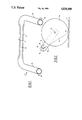
- FIG. 1 is a perspective view of the axle
- FIG. 2 is a side view in the direction of arrow F of FIG. 1.
- the rear axle includes two swinging wheel arms 1a and 1b connected together by a semirigid cross piece 1c.
- Each of the arms has a shaft 2a or 2b for a wheel such as the wheel 3a.
- the axle is made in one piece from a tube of circular section.
- the cross piece 1c has a Y shaped section obtained by deformation of the tube.
- the lower leg 1d of this section is oriented so that the plane of symmetry P passing through this leg also passes through the straight line D joining the points of contact of the wheels with the ground 4, that is to say through the vertical projections of shafts 2a and 2b on the ground plane.
- the Y section of cross piece 1c increases the moment of inertia under flexion of this cross piece and reduces its moment of inertia under torsion. Because of the orientation of the section, the maximum flexion modulus is obtained in the zones working under traction, under the effect of the transverse forces which are exerted on the wheels in the direction of the straight line D, that is to say in the upper legs 1e and 1f of the cross piece; the flexional stress is thus minimum.
- Cross piece 1c is very rigid in the horizontal plane as well as in the vertical plane; the deformations corresponding respectively to a spread variation and to a rake variation are thus relatively small.
Abstract
Description
Claims (2)
Applications Claiming Priority (2)
| Application Number | Priority Date | Filing Date | Title |
|---|---|---|---|
| FR8608620 | 1986-06-10 | ||
| FR8608620A FR2599674B1 (en) | 1986-06-10 | 1986-06-10 | REAR AXLE OF MOTOR VEHICLE |
Publications (1)
| Publication Number | Publication Date |
|---|---|
| US4830400A true US4830400A (en) | 1989-05-16 |
Family
ID=9336333
Family Applications (1)
| Application Number | Title | Priority Date | Filing Date |
|---|---|---|---|
| US07/056,601 Expired - Lifetime US4830400A (en) | 1986-06-10 | 1987-05-29 | Rear axle for motor vehicles |
Country Status (6)
| Country | Link |
|---|---|
| US (1) | US4830400A (en) |
| EP (1) | EP0249537B1 (en) |
| JP (1) | JPS62299402A (en) |
| DE (1) | DE3764404D1 (en) |
| ES (1) | ES2017508B3 (en) |
| FR (1) | FR2599674B1 (en) |
Cited By (7)
| Publication number | Priority date | Publication date | Assignee | Title |
|---|---|---|---|---|
| US5409255A (en) * | 1990-08-10 | 1995-04-25 | Benteler Industries, Inc. | Twist beam axle |
| GB2355698A (en) * | 1999-10-28 | 2001-05-02 | Meritor Heavy Vehicle Sys Ltd | Vehicle axle |
| US20030071516A1 (en) * | 2000-03-22 | 2003-04-17 | Vincent Biard | Vehicle axle crosspiece with antiroll articulations and vehicle axle comprising same |
| DE19631975B4 (en) * | 1995-08-18 | 2007-05-03 | Volkswagen Ag | Motor vehicle axle |
| US20080191443A1 (en) * | 2005-03-16 | 2008-08-14 | Magna International Inc. | Twist Beam Axle with Integral Torsion Bar |
| US20110101771A1 (en) * | 2009-11-04 | 2011-05-05 | Oswaldo De Freitas Junior | Steering axle |
| US20150191070A1 (en) * | 2012-07-03 | 2015-07-09 | Pantero Technologies Inc. | Semi-independent suspension system for a low-floor vehicle |
Families Citing this family (11)
| Publication number | Priority date | Publication date | Assignee | Title |
|---|---|---|---|---|
| FR2662118A1 (en) * | 1990-05-17 | 1991-11-22 | Peugeot | REAR TRAIN OF A MOTOR VEHICLE. |
| US5324073A (en) * | 1990-08-10 | 1994-06-28 | Benteler Industries, Inc. | Tuned twist beam axle |
| JPH05278424A (en) * | 1992-01-22 | 1993-10-26 | Benteler Ind Inc | Twist beam axle |
| DE4447971B4 (en) * | 1994-05-13 | 2007-03-29 | GM Global Technology Operations, Inc., Detroit | Motor vehicle rear axle |
| DE19941993C1 (en) | 1999-09-02 | 2000-12-14 | Benteler Werke Ag | Tubular profile manufacturing method for passenger vehicle rear axle uses cold-forming of central part of round cross-section steel tube before localised heating and hardening in water |
| CZ296802B6 (en) | 2000-05-31 | 2006-06-14 | Benteler Ag | Twist-beam axle with transverse torsion bar |
| DE102006024605A1 (en) * | 2006-05-26 | 2007-11-29 | Bayerische Motoren Werke Ag | Guide e.g. for vehicle wheel suspension, made from fiber reinforced plastic material and bar has relatively rigid section and joint |
| DE102007007439A1 (en) * | 2007-02-15 | 2008-08-21 | Bayerische Motoren Werke Aktiengesellschaft | Axis of a two-lane vehicle with a torsionally soft composite link |
| JP4301307B2 (en) | 2007-03-01 | 2009-07-22 | トヨタ自動車株式会社 | Torsion beam suspension |
| ITTO20080521A1 (en) * | 2008-07-08 | 2010-01-08 | Sistemi Sospensioni Spa | CROSSBEAM FOR A REAR BRIDGE SUSPENSION WITH TORCH FOR MOTOR VEHICLES AND PROCEDURE FOR ITS MANUFACTURING |
| FR3032384A1 (en) * | 2015-02-11 | 2016-08-12 | Peugeot Citroen Automobiles Sa | METHOD FOR MANUFACTURING A PLURALITY OF TYPES OF ANTI-ROLL BAR DIFFERENT BY STIFFNESS IN TORSION OF BARS |
Citations (12)
| Publication number | Priority date | Publication date | Assignee | Title |
|---|---|---|---|---|
| US312502A (en) * | 1885-02-17 | Wagon-axle | ||
| US428291A (en) * | 1890-05-20 | Channel-iron | ||
| US2132725A (en) * | 1936-04-23 | 1938-10-11 | Spencer Trailer Company | Axle |
| US2148714A (en) * | 1936-12-24 | 1939-02-28 | Urschel Engineering Company | Axle |
| US2218127A (en) * | 1938-04-04 | 1940-10-15 | Urschel Engineering Company | Automotive vehicle axle |
| FR1239096A (en) * | 1958-10-24 | 1960-08-19 | Improvement of tubular shafts, more particularly for cardan shafts of agricultural machines | |
| US3175842A (en) * | 1962-04-05 | 1965-03-30 | Lubbock Machine & Supply | Crank arm axle |
| US3844583A (en) * | 1973-02-21 | 1974-10-29 | T Sakow | Vehicle torsion bar |
| US3896895A (en) * | 1972-11-16 | 1975-07-29 | Hamburger Hochbahn Ag | Axle arrangement for vehicles |
| US3966270A (en) * | 1975-08-13 | 1976-06-29 | General Signal Corporation | Fluid brake control system |
| US4343375A (en) * | 1979-10-22 | 1982-08-10 | Manning Donald L | Vehicle drive wheel suspension |
| US4429899A (en) * | 1979-09-07 | 1984-02-07 | Nhk Spring Co., Ltd. | Hollow stabilizer for vehicle |
Family Cites Families (3)
| Publication number | Priority date | Publication date | Assignee | Title |
|---|---|---|---|---|
| GB412173A (en) * | 1932-12-14 | 1934-06-14 | Samuel Whyte | Improvements relating to case-hardening |
| DE2425740C3 (en) * | 1974-05-28 | 1980-10-16 | Volkswagenwerk Ag, 3180 Wolfsburg | Rear axle for motor vehicles |
| FR2550495B1 (en) * | 1983-08-10 | 1985-11-29 | Renault | REAR SUSPENSION WITH INDEPENDENT WHEELS |
-
1986
- 1986-06-10 FR FR8608620A patent/FR2599674B1/en not_active Expired - Lifetime
-
1987
- 1987-05-27 JP JP62131055A patent/JPS62299402A/en active Pending
- 1987-05-29 US US07/056,601 patent/US4830400A/en not_active Expired - Lifetime
- 1987-06-04 EP EP87401259A patent/EP0249537B1/en not_active Expired
- 1987-06-04 DE DE8787401259T patent/DE3764404D1/en not_active Expired - Lifetime
- 1987-06-04 ES ES87401259T patent/ES2017508B3/en not_active Expired - Lifetime
Patent Citations (12)
| Publication number | Priority date | Publication date | Assignee | Title |
|---|---|---|---|---|
| US312502A (en) * | 1885-02-17 | Wagon-axle | ||
| US428291A (en) * | 1890-05-20 | Channel-iron | ||
| US2132725A (en) * | 1936-04-23 | 1938-10-11 | Spencer Trailer Company | Axle |
| US2148714A (en) * | 1936-12-24 | 1939-02-28 | Urschel Engineering Company | Axle |
| US2218127A (en) * | 1938-04-04 | 1940-10-15 | Urschel Engineering Company | Automotive vehicle axle |
| FR1239096A (en) * | 1958-10-24 | 1960-08-19 | Improvement of tubular shafts, more particularly for cardan shafts of agricultural machines | |
| US3175842A (en) * | 1962-04-05 | 1965-03-30 | Lubbock Machine & Supply | Crank arm axle |
| US3896895A (en) * | 1972-11-16 | 1975-07-29 | Hamburger Hochbahn Ag | Axle arrangement for vehicles |
| US3844583A (en) * | 1973-02-21 | 1974-10-29 | T Sakow | Vehicle torsion bar |
| US3966270A (en) * | 1975-08-13 | 1976-06-29 | General Signal Corporation | Fluid brake control system |
| US4429899A (en) * | 1979-09-07 | 1984-02-07 | Nhk Spring Co., Ltd. | Hollow stabilizer for vehicle |
| US4343375A (en) * | 1979-10-22 | 1982-08-10 | Manning Donald L | Vehicle drive wheel suspension |
Cited By (12)
| Publication number | Priority date | Publication date | Assignee | Title |
|---|---|---|---|---|
| US5409255A (en) * | 1990-08-10 | 1995-04-25 | Benteler Industries, Inc. | Twist beam axle |
| US5520407A (en) * | 1990-08-10 | 1996-05-28 | Alatalo; Clarke E. | Twist beam axle |
| DE19631975B4 (en) * | 1995-08-18 | 2007-05-03 | Volkswagen Ag | Motor vehicle axle |
| GB2355698A (en) * | 1999-10-28 | 2001-05-02 | Meritor Heavy Vehicle Sys Ltd | Vehicle axle |
| US6543857B1 (en) | 1999-10-28 | 2003-04-08 | Meritor Heavy Vehicle Systems Limited | Vehicle axle |
| GB2355698B (en) * | 1999-10-28 | 2003-09-17 | Meritor Heavy Vehicle Sys Ltd | Vehicle axle |
| US20030071516A1 (en) * | 2000-03-22 | 2003-04-17 | Vincent Biard | Vehicle axle crosspiece with antiroll articulations and vehicle axle comprising same |
| US6688619B2 (en) * | 2000-03-22 | 2004-02-10 | Compagnie Générale des Etablissements MICHELIN-MICHELIN & Cie | Vehicle axle crosspiece with antiroll articulations and vehicle axle comprising same |
| US20080191443A1 (en) * | 2005-03-16 | 2008-08-14 | Magna International Inc. | Twist Beam Axle with Integral Torsion Bar |
| US20110101771A1 (en) * | 2009-11-04 | 2011-05-05 | Oswaldo De Freitas Junior | Steering axle |
| US20150191070A1 (en) * | 2012-07-03 | 2015-07-09 | Pantero Technologies Inc. | Semi-independent suspension system for a low-floor vehicle |
| US9527368B2 (en) * | 2012-07-03 | 2016-12-27 | Pantero Technologies Inc. | Semi-independent suspension system for a low-floor vechicle |
Also Published As
| Publication number | Publication date |
|---|---|
| EP0249537B1 (en) | 1990-08-22 |
| DE3764404D1 (en) | 1990-09-27 |
| FR2599674A1 (en) | 1987-12-11 |
| FR2599674B1 (en) | 1990-06-08 |
| ES2017508B3 (en) | 1991-02-16 |
| EP0249537A1 (en) | 1987-12-16 |
| JPS62299402A (en) | 1987-12-26 |
Similar Documents
| Publication | Publication Date | Title |
|---|---|---|
| US4830400A (en) | Rear axle for motor vehicles | |
| KR910007880B1 (en) | Semi-rigid axle for a vehicle | |
| US4406474A (en) | Vehicle fender attachment and support structure | |
| EP0794075B1 (en) | Deformable suspension arm for automotive vehicle | |
| CA2174878A1 (en) | Combined vehicle suspension torque rod and sway bar | |
| JPS62105709A (en) | Suspension of vehicle | |
| JPH01244911A (en) | Wheel suspension system for drive front axle of automobile | |
| US2775467A (en) | Wheel suspension for motor vehicles | |
| US4043571A (en) | Suspension system | |
| US4271920A (en) | Automobile vehicle with transverse engine-drive unit | |
| US3934487A (en) | Vehicle steering column | |
| SE447821B (en) | DEVICE FOR PREPARING A CHARGE OF COMPOSITIVE MATERIAL FOR A COMPOSITION PLANT | |
| EP0000979A1 (en) | Rigid axle suspension system for a vehicle | |
| JPH0399915A (en) | Axle suspension device | |
| FR2593440B1 (en) | MOTOR VEHICLE SEAT FRAME OR THE LIKE | |
| EP0683088B1 (en) | Front wheel suspension assembly with double transversal triangles and motor vehicle equipped with such an assembly | |
| EP1199195A3 (en) | Axle linkage for industrial vehicle | |
| JPS6037841Y2 (en) | Work vehicle suspension structure | |
| US4243087A (en) | Self-adjusting tire chain | |
| FI82418B (en) | Leaf spring | |
| RU2034715C1 (en) | Vehicle end part | |
| JPH0330221Y2 (en) | ||
| JPH0243828Y2 (en) | ||
| JP2502655Y2 (en) | Suspension member | |
| JPH0747206Y2 (en) | Torsion beam type suspension |
Legal Events
| Date | Code | Title | Description |
|---|---|---|---|
| AS | Assignment |
Owner name: AUTOMOBILES PEUGEOT & AUTOMOBILES, 75, AV. DE LA G Free format text: ASSIGNMENT OF ASSIGNORS INTEREST.;ASSIGNOR:PENOT, JEAN;REEL/FRAME:004718/0932 Effective date: 19870505 Owner name: CITROEN, 62, BD. VICTOR HUGO, NEUILLY SUR SEINE, F Free format text: ASSIGNMENT OF ASSIGNORS INTEREST.;ASSIGNOR:PENOT, JEAN;REEL/FRAME:004718/0932 Effective date: 19870505 |
|
| STCF | Information on status: patent grant |
Free format text: PATENTED CASE |
|
| FEPP | Fee payment procedure |
Free format text: PAYOR NUMBER ASSIGNED (ORIGINAL EVENT CODE: ASPN); ENTITY STATUS OF PATENT OWNER: LARGE ENTITY |
|
| FPAY | Fee payment |
Year of fee payment: 4 |
|
| FEPP | Fee payment procedure |
Free format text: PAYOR NUMBER ASSIGNED (ORIGINAL EVENT CODE: ASPN); ENTITY STATUS OF PATENT OWNER: LARGE ENTITY Free format text: PAYER NUMBER DE-ASSIGNED (ORIGINAL EVENT CODE: RMPN); ENTITY STATUS OF PATENT OWNER: LARGE ENTITY |
|
| FPAY | Fee payment |
Year of fee payment: 8 |
|
| FEPP | Fee payment procedure |
Free format text: PAYER NUMBER DE-ASSIGNED (ORIGINAL EVENT CODE: RMPN); ENTITY STATUS OF PATENT OWNER: LARGE ENTITY |
|
| FPAY | Fee payment |
Year of fee payment: 12 |