US4808145A - Tripod type constant velocity joint - Google Patents
Tripod type constant velocity joint Download PDFInfo
- Publication number
- US4808145A US4808145A US07/115,986 US11598687A US4808145A US 4808145 A US4808145 A US 4808145A US 11598687 A US11598687 A US 11598687A US 4808145 A US4808145 A US 4808145A
- Authority
- US
- United States
- Prior art keywords
- aligning member
- groove
- cylindrical
- roller
- cylindrical surface
- Prior art date
- Legal status (The legal status is an assumption and is not a legal conclusion. Google has not performed a legal analysis and makes no representation as to the accuracy of the status listed.)
- Expired - Fee Related
Links
Images


Classifications
-
- F—MECHANICAL ENGINEERING; LIGHTING; HEATING; WEAPONS; BLASTING
- F16—ENGINEERING ELEMENTS AND UNITS; GENERAL MEASURES FOR PRODUCING AND MAINTAINING EFFECTIVE FUNCTIONING OF MACHINES OR INSTALLATIONS; THERMAL INSULATION IN GENERAL
- F16D—COUPLINGS FOR TRANSMITTING ROTATION; CLUTCHES; BRAKES
- F16D3/00—Yielding couplings, i.e. with means permitting movement between the connected parts during the drive
- F16D3/16—Universal joints in which flexibility is produced by means of pivots or sliding or rolling connecting parts
- F16D3/20—Universal joints in which flexibility is produced by means of pivots or sliding or rolling connecting parts one coupling part entering a sleeve of the other coupling part and connected thereto by sliding or rolling members
- F16D3/202—Universal joints in which flexibility is produced by means of pivots or sliding or rolling connecting parts one coupling part entering a sleeve of the other coupling part and connected thereto by sliding or rolling members one coupling part having radially projecting pins, e.g. tripod joints
- F16D3/205—Universal joints in which flexibility is produced by means of pivots or sliding or rolling connecting parts one coupling part entering a sleeve of the other coupling part and connected thereto by sliding or rolling members one coupling part having radially projecting pins, e.g. tripod joints the pins extending radially outwardly from the coupling part
-
- Y—GENERAL TAGGING OF NEW TECHNOLOGICAL DEVELOPMENTS; GENERAL TAGGING OF CROSS-SECTIONAL TECHNOLOGIES SPANNING OVER SEVERAL SECTIONS OF THE IPC; TECHNICAL SUBJECTS COVERED BY FORMER USPC CROSS-REFERENCE ART COLLECTIONS [XRACs] AND DIGESTS
- Y10—TECHNICAL SUBJECTS COVERED BY FORMER USPC
- Y10S—TECHNICAL SUBJECTS COVERED BY FORMER USPC CROSS-REFERENCE ART COLLECTIONS [XRACs] AND DIGESTS
- Y10S464/00—Rotary shafts, gudgeons, housings, and flexible couplings for rotary shafts
- Y10S464/904—Homokinetic coupling
- Y10S464/905—Torque transmitted via radially extending pin
Definitions
- This invention relates to tripod type constant velocity joint.
- symbol H is a cup-shaped housing and symbol S is a shaft.
- Numeral 1 is a trunnion mounted on the shaft.
- Symbol R is a spherical roller fitted to the trunnion 1 by a needle 2.
- Numeral 3 is a stopper and numeral 5 is a support ring.
- Formed in the housing H are three pairs of grooves 4 extending to an axial direction. The spherical roller R is moved slidably on a cylindrical surface 4a of the groove 4.
- Mounted between the housing H and the shaft S is a boot which is not illustrated.
- a relative axial displacement of the strip-like members and the outer element becomes a slide, so that the most remarkable feature of a slide and tripod type constant velocity joint is that, a friction resistance in a slide direction that is small is lost. That is, the spherical roller is rolled in the guide groove of the outer component. Accordingly, the disadvantage is that friction coefficient is remarkably increased and slide resistance becomes very large.
- This invention aims at solving the problems of the aforesaid conventional techniques. More particularly, this invention provides a novel tripod type constant velocity joint which enables to reduce an axial force and prevent resonance of a vehicle body due to the axial force by analyzing the factors for causing the axial force as well as the influence on the axial force.
- the result of my analysis is that the axial force is caused by the following three friction resistances; a friction resistance f 1 acted on the trunnion 1 when the spherical roller R performs its rolling movement, a friction resistance f 2 of the roller R to the groove 4 in the case of the former slides in the axial direction of the trunnion 1, and a friction resistance f 3 of the roller R to the trunnion 1 (needle 2) when the roller R slides in the axial direction of the trunnion 1. It has been found that the axial force due to the friction resistances f 2 and f 3 is large.
- FIG. 7 shows the results of my analysis on the influence of occurrence of the axial force.
- FIG. 4 shows the condition of a relative displacement of the roller R at the movement time of the joint relative to the groove 4.
- the contact point A is displaced to a position B as shown in FIG. 5, thereby a component of force Ft of load FA occurs.
- the component of force Ft is, as shown in FIG. 6, divided into a component of force Ft cos ⁇ to be balanced with the sum of the friction resistances f 2 and f 3 and a component of force Ft sin ⁇ in a direction of the shaft S. Addition of the component of force Ft sin ⁇ in the shaft direction to the friction resistance f 1 appears as the axial force.
- a contact point of the cylindrical surface 4a and the spherical roller R is displaced out of the plane (rotational surface of the trunnion) including the axial lines of the three trunnions, and a direction of force Ft occurred on the contact point is intersected with the rotational surface K.
- the tripod type constant velocity joint comprises a housing including three grooves each of which has curved surfaces opposing each other in a circumferential direction; a shaft inserted into the housing; three trunnions mounted on said shaft and outwardly extending right-angled relative to an axis of said shaft; three rollers rotatably mounted on said three trunnions; and aligning member means disposed between said three rollers of each and the curved surfaces of each of said three grooves; said aligning member means being movable along the curved surfaces of said groove.
- FIG. 1 is a section view of a main part of a conventional tripod type constant velocity joint.
- FIG. 2 is a perspective view of a housing in the conventional joint.
- FIG. 3 shows a relationship of a rotation angle with an axial force in the conventional joint.
- FIG. 4 shows a relative displacement of a spherical roller and a groove at the time when the conventional joint is moved.
- FIG. 5 shows mechanism of occurrence of an axial force in the conventional joint.
- FIG. 6 shows mechanism of occurrence of the axial force in the conventional joint.
- FIG. 7 shows an analytic chart of occurrence of the axial force in the conventional joint.
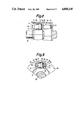
- FIG. 8 is a section view of a first example of a tripod type constant velocity according to this invention.
- FIG. 9 is a front view of a main part of the first example.
- FIG. 10 is an enlarged view of an aligning member in the first example.
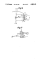
- FIG. 11 is a view of an operation of the first example.
- FIG. 12 is a front view of a main part of a second example, in which the function of an aligning member is described.
- FIGS. 13 and 14 are front views of the main part of the second example.
- FIG. 15 is a perspective view of an aligning member in FIG. 14.
- FIGS. 16 and 17 are views of the function of the aligning member in the second example.
- FIG. 18 is a side view of an aligning member of a third embodiment.
- FIGS. 19 and 20 respectively are a perspective view and a side view of a first modification of the aligning member in the third embodiment.
- FIG. 21 is a perspective view of a second modification thereof in the third embodiment.
- FIG. 22 is a perspective view of a third modification thereof in the third embodiment.
- FIG. 23 is a side view of a first modification of an aligning member in a fourth embodiment.
- FIG. 24 is a side view of a second modification thereof in the fourth modification.
- FIG. 25 is a plan view of the aligning member in FIG. 24.
- FIG. 26 is a perspective view of the aligning member in FIG. 24.
- FIG. 27 is a plan view of a third modification of the aligning member in the fourth embodiment.
- FIG. 28 is a section view of a main part of a fifth embodiment.
- FIG. 29 is a front view of the main part thereof.
- FIG. 30 is a section view of the construction for supporting an aligning member in the fifth embodiment.
- FIG. 31 is an exploded perspective view of the aligning member having two segments in the fifth embodiment.
- FIGS. 32 to 35 are views for showing various variations of the aligning member in the fifth embodiment.
- FIG. 36 shows a graph for comparing a resultant axial force of a tripod type constant velocity joint of this invention with that of the prior art.
- FIG. 37 shows a graph for showing a relationship of an actual vehicle speed and its side acceleration in the present invention and the prior art respectively.
- FIG. 8 to 11 there is shown a cup-shaped housing H 1 , inside which three grooves 11 are extended in an axial direction.
- Symbol S 1 is a shaft.
- Numeral 12 is one of three trunnions mounted on the shaft S 1 .
- Symbol R 1 is a cylindrical roller movably inserted into the trunnion 12 by means of a needle 13.
- Numeral 14 is a stopper having a slight clearance in an axial direction of the trunnion 12.
- Numeral U 1 is a U-shaped aligning member which is disposed so as to hold the cylindrical roller R 1 between a cylindrical surface r 1 as a raceway formed at both side walls of the groove 11 and the cylindrical roller R 1 .
- the surface of the aligning member U 1 at the side of the groove 11 is a cylindrical surface r 2 sliding with the cylindrical surface r 1 of the groove 11, while the surface thereof at the side of the cylindrical roller R is a plane surface P on which the roller R 1 is moved arcuately by rotation of the trunnion 12.
- the U-shaped aligning member U 1 is not dismounted in the axial direction from the groove 11, because it is supported by a pair of supporters 15.
- the aligning member U 1 makes a relative movement for the housing H 1 within the groove 11 as shown in arrow mark E.
- the aligning member U 1 is movable relative to the housing H 1 within the groove 11 and firmly supported to the housing by a suitable supporting means so that it may not be dropped out.
- the cylindrical roller R 1 makes an arcuate movement by rotation of the trunnion 12 and is moved from the zone [I] to the zone [II]. Since the inside of the aligning member U 1 contacting the roller R 1 is formed by the plane surface P, the roller R 1 is moved in an arcuate form upon the plane surface P. In the meantime, the aligning member U 1 is moved relatively along the cylindrical surface r 1 and follows smoothly an inclination of the cylindrical roller R 1 . Then, the cylindrical roller R 1 does not slide in the axial direction of the trunnion 12, and slidable within such a clearance that no obstacle is given for a slight eccentric movement and rolling at the rotation time of joint.
- a contact line of the cylindrical roller R 1 and the aligning member U 1 always corresponds to a contour of the cylindrical roller R 1 , a direction of force arising on the contact line always exists within the plane surface (a rotational surface K 1 of the trunnion) including the axes of the three trunnions 12, so that any axial force does not occur and a friction resistance to be affected by the axial force nearly disappears.
- an axial displacement of the shaft S 1 toward the housing H 1 is feasible when the cylindrical roller R 1 is moved on the plane surface P of the aligning member U 1 , so that a sliding friction hardly occurs between the roller R 1 and the aligning member U 1 .
- the U-shaped aligning member is mounted between the cylindrical roller and the groove, and movable relative to the housing. Further, a contact surface of the aligning member and the cylindrical roller is plane and the aligning member is moved relative to the cylindrical roller.
- a center of the joint may make an eccentric movement, and the contact surface of the cylindrical roller and the aligning member becomes uniform, thereby the friction resistances f2, f3 are reduced and a component of force Ft sin ⁇ in the axial direction of the shaft S does not occur. Accordingly, it is possible to prevent resonance of the vehicle body due to occurrence of the axial force.
- the aligning member does not slide in the axial direction on the groove, so that a sliding resistance to the axial direction due to movement of the cylindrical roller can be maintained to a lower level.
- FIG. 36 shows the measured result of the resultant axial force occurred when a certain torque is applied for a drive shaft assembly using a tripod type constant velocity joint. It was measured by a suitable test device.
- "TRI-J” indicates a conventional tripod type constant velocity joint (as shown in FIGS. 1 and 2), while “UTJ” indicates a novel tripod type constant velocity joint according to the first embodiment of this invention.
- the resultant axial force of the applied torque in this invention is about half as low as that in the conventional joint.
- FIG. 37 shows the measured results of relationship of vehicle speed with side acceleration in an actual vehicle and confirms the correctness of the measured test results in FIG. 36.
- the aligning member can perform a very suitable aligning function.
- the axial line Y 0 --Y 0 of the trunnion 12 is inclined up to a position of Y 1 --Y 1 at maximum due to eccentric amount ⁇ of a joint center O 0 which is a proper feature of the tripod type constant velocity joint. Since the trunnion 12 and the cylindrical roller R 1 having it are inclined at the same angle, a load distribution of a contact surface of the cylindrical roller R 1 and the aligning member U 1 is transferred from a uniform condition to an outer side of the width of the aligning member U 1 . As a result, the aligning member U 1 is not moved about a center O 1 of the trunnion 11. As shown in FIG. 13, the aligning member U 1 is not slided inwardly of the cylindrical surface of the groove 11, and contacts a side end J 1 .
- Another end (non-load side) of the aligning member U 1 having no relation with torque transmission is displaced outwardly, because there is a gap g 2 between the groove 11 and the aligning member U 1 .
- an end of the aligning member may contact an inner wall of the housing H 1 at a position C.
- the aligning member according to the second embodiment can perform a stable and effective aligning function.
- FIG. 14 shows a front view of the second embodiment corresponding to FIG. 9 and FIG. 15 shows a perspective view of the aligning member U 2 in FIG. 14.
- the aligning member U 2 is, on the cylindrical surface r 2 of the aligning member of the first embodiment, provided with a non-contact portion m which has no contact with the cylindrical surface r 1 of the groove 11.
- the non-sliding portion m is formed with a same width in a longitudinal direction on a center portion of the cylindrical surface r 2 . After that, it(m) is bent in a U-shape as shown in FIG. 15. Both sides of the non-contact portion m are, in parallel with each other, formed at r 3 and r 4 .
- the width b of the non-contact portion m is defined so as to satisfy the following formula. ##EQU1## wherein R 1 ' is a radius of curvature of the cylindrical roller r 1 of the groove 11, ⁇ is a sliding coefficient of the friction resistance of the aligning member U 2 and the groove 11, a is a reduction coefficient of the friction resistance between the aligning member U 2 and the cylindrical roller R 1 , thereby a ⁇ 1 is obtained.
- the aligning member U 2 is movable on the cylindrical surface r 1 under the condition that a curvature center O 1 of the cylindrical surface r 1 of the groove 11 and a curvature center O 1 ' of the cylindrical surfaces r 3 , r 4 of the aligning member U 2 are on the nearly same position.
- the width of the non-sliding portion of the aligning member U 2 is expressed with b and the aligning member U 2 is slidable with the groove 11 on the cylindrical surfaces r 3 and r 4 .
- a sliding force f is expressed with the following formula: ##EQU2## wherein ⁇ is vertical relative to axis line Y 0 --Y 0 of the trunnion when the joint angle is zero, and a surface for connecting a surface passing a curvature center O 1 of the cylindrical surface r 1 , a curvature center O 1 and the aforesaid point L 1 , respectively.
- a sliding force f is to be larger than the sum of
- the aligning member U 1 is provided with the non-siding portion whose width b is predetermined so as to satisfy the aforesaid formula (1). Accordingly, the aligning member U 2 slides on the cylindrical surface r 1 of the groove 11 having the cylindrical surfaces r 3 and r 4 and moves about the curvature center O 1 .
- the aligning member is provided with the non-sliding portion m having the width b, a gap G arising between the cylindrical surface r 1 of the groove 11 and the cylindrical roller R 1 can be employed as a grease reservoir, thereby a slide movement of the aligning member U 2 becomes easier.
- the aligning member slides more smooth. Therefore, it is effective to carry out a superficial treatment for reducing the friction coefficient on the whole or partial surface of the cylindrical roller, the aligning member, the groove or the like.
- the aligning member is provided with the non-sliding portion, thereby sliding of the aligning member relative to the groove hardly arises.
- FIGS. 18 to 22 A third embodiment of this invention will be described with regard to FIGS. 18 to 22.
- This embodiment relates to a modification of a curved portion of the U-shaped aligning member. Since the construction of this embodiment is the same as that of the first example except for the aligning member, I will describe the construction of only the aligning member.
- the aligning member as shown in FIG. 10 is fabricated in U-shape as shown in FIG. 18.
- the former in FIG. 10 has a cylindrical surface r 2 contacting the cylindrical surface r 1 of the groove 11 and a plane surface P contacting the cylindrical roller R.
- the construction of this embodiment is effective for the production of a heat-treated aligning member which can withstand a large load at the actuation time of the joint. Generally, a dimensional unbalance due to bending treatment as well as heat treatment has been unavoidable to some extent.
- the inner and outer sides A 1 , A 2 at a curved portion are different from the inner and outer sides B 1 , B 2 at a free end, so that it is difficult to obtain a uniform dimension of the aligning member.
- a sectional area of the curved portion is to be small.
- the third example will be described with reference to FIGS. 19 and 20 while referring to FIGS. 8 and 9.
- a material s having the cylindrical surface r 2 contacting the cylindrical surfaces r 1 , r 1 of the groove 11 and the plane surface P contacting the cylindrical roller R is cutaway with a certain thickness at a portion b to be bent, thereby a portion f having a small thickness is formed and its sectional area becomes small.
- Such material S is bent into U-shaped as shown in FIG. 20.
- the bending work becomes so easy that it is feasible to make uniform the dimensions of the inner and outer sides at the bending portion as well as at the free end and also to correct or modify them. As shown in FIG. 20, it is possible to determine accurately the dimensions of the inner and outer dimensions A 3 , A 4 at the bending portion as well as those of the inner and outer dimensions B 3 , B 4 at the free end.
- FIG. 21 shows another modification of the U-shaped aligning member U 3 according to the third embodiment.
- FIG. 21 shows an example of the aligning member having the non-sliding portion m on the cylindrical surface r 2 as shown in FIG. 15.
- a U-shaped aligning member U 4 is divided into two segments.
- the other construction is the same as the tripod type constant velocity joint of the first embodiment.
- FIG. 23 shows a first modification of the aligning member U 4 of this embodiment, in which a pair of segments u 4 , u 4 are provided.
- Symbol r 5 is a cylindrical surface contacting the cylindrical surface r 1 of the groove 11.
- Symbol p is a contact surface with the cylindrical roller R and forms a plane surface.
- Each of the two segments u 4 is obtained by drawing a material having the cylindrical surface r 5 and the plane surface p .
- Each segment u 4 is transformed into a straight member by cutting.
- Symbol W is a bent U-shaped flat spring having light springiness. An end of the each segments u 4 is provided with a hole, thereby two ends of the flat spring W are fixedly inserted into and two holes of the two segments u 4 . Accordingly, the pair of segments u 4 as the aligning member are fixed with each other by means of the flat spring W so as to be moved relatively.
- the U-shaped aligning member U 4 is of a slightly open type. When fitting such aligning member U 4 in the groove 11, the cylindrical surface r 5 thereof contacts lightly the cylindrical surface r 1 of the groove 11.
- the pair of segments u 4 are linked with each other by the flat spring W so as to enable relative movement. If such a function is satisfied, the joint method and shape of the pair of segments u 4 may be modified optionally. Further, a distance between the cylindrical surfaces r 5 and r 5 of the pair of segments u 4 must be equal to that between the cylindrical surfaces r 1 and r 1 of the groove 11, so that the flat spring W has in advance a certain curvature.
- the accuracy of thickness of the pair of segments u 1 can be cold-molded so as to conform with a distance between the cylindrical surface r 1 of the groove 11 and the cylindrical roller R 1 . Further, since each segment u 1 is a straight member, no deformation due to heat treatment will occur. Accordingly, when the U-shaped aligning member U 4 is mounted in the groove 11, a dimension between the plane surfaces p and p of the two segments u 4 can be set accurately. Namely, it is possible to control smaller a gap between the pair of segments u 4 and the cylindrical roller R 1 . In addition, such U-shaped aligning member U 4 has a simple profile, it can be manufactured at a low cost.
- any slight deformation thereof prior to mounting may be adjusted by springiness of the flat spring W. Because the then springiness is moderate, the aligning member U 4 can maintain a good aligning function.
- FIGS. 24 to 26 shows a second modification of the aligning member of the fourth embodiment.
- a bending portion of a rightside segment u 4 is partially cutaway, thereby a lug t 1 is formed, while that of a leftside segment u 4 is also partially cutaway, thereby both segments u 4 are fitted each other and fixed together by a connecting steel tube P so as to enable relative movement.
- a clearance X is arranged in order to vary a gap between the both segments u 4 .
- a relative displacement of the two segments u 4 is possible within the connecting tube P' in which both lugs t 1 are connected with each other.
- the function and effect of the second modification are the same as those of the first modification.
- FIG. 27 shows a third modification of the fourth embodiment, in which the cylindrical surface r 3 in the third modification is provided with the non-sliding portion m like the example in FIG. 15. Likewise, it is of course possible to provide the aligning member U 4 with the non-sliding portion m.
- symbol H 2 is a cup-shaped housing, inside which three grooves are formed in the axial direction.
- Symbol S 2 is a shaft and numeral 12 is one of three trunnions mounted on the shaft S 2 .
- Symbol R 2 is a cylindrical roller movably inserted into the trunnion 12 by way of the needle 13.
- Numeral 14 is the stopper having a slight clearance in the axial direction of the trunnion 12.
- Numeral 15 is the supporter.
- Symbol T is an aligning member which is divided into two segments disposed between the cylindrical surface r 2 and the cylindrical roller R 2 .
- the aligning member is provided with cylindrical surfaces r 2 , r 2 contacting the cylindrical surface r 1 of the groove 11 and the plane surface P on which the cylindrical roller R 2 is movable arcuately by rotation of the trunnion 12. Accordingly, each aligning member T in each groove 11 is, on the cylindrical surfaces r 2 , r 2 , movable relative to the cylindrical surface r 1 of the groove 11.
- cylindrical surface r 1 of the groove 11 is concave as shown in FIG. 32, that is convex as shown in FIG. 33.
- cylindrical surface r 2 of the aligning member T is convex, while in the latter case that is covex. Any combination is acceptable, but the former combination is more preferable in view of manufacture.
- an angle ⁇ (a holding angle of the aligning member T) of a surface containing a plane surface P of the aligning member T relative to a tangent line drawn on a tangent line of the cylindrical surface r 1 and the cylindrical r 2 must be more than the angle to cause a component of force f, i.e. "sliding" enough to withstand a sliding and friction resistance of the aligning member T.
- the width B of the aligning member T is limited, 0 the radius r 1 ' is also limited to obtain the holding angle ⁇ of the aligning member T.
- Symbol m is a non-sliding portion so as to avoid sliding with the cylindrical surface r 1 of the groove 11, which is formed e.g. when drawing and fabricating the aligning member T.
- the non-sliding portion m is extended with the same width b in a width direction of the aligning member T. Accordingly, two cylindrical surfaces r 2 , r 2 are formed in parallel with each other at both sides of the nonsliding portion m, and perform the function of the sliding surface with the cylindrical surface r 1 of the groove 11.
- the holding angle ⁇ is smaller, the non-sliding portion m does not bring about sliding. To avoid it, the two cylindrical surfaces r 2 r 2 are formed.
- the contact surface of the aligning member T and the cylindrical surface of the groove 11 appears on the cylindrical surfaces r 2 , r 2 at the both sides of the aligning member T. It is required to determine suitably the width B of the aligning member T and the width b of the non-sliding portion m in view of contact surface pressure, friction or the like.
- r 1 ' is expressed by the following formula. ##EQU6##
- ⁇ is a friction coefficient of the aligning member relative to the cylindrical surface r 1 and the cylindrical roller R when the aligning member slides.
- the cylindrical surface r 2 does not slide on the cylindrical surface r 1 and makes a relative movement. Due to this movement, the plane surface P of the aligning member T is tilted in the same way as the sliding case and can follow the inclination of the cylindrical roller R 2 . Further, it is possible to transform r 1 ' in the former combination and r 2 ' in the latter combination into a limitless radius i.e. a plane surface.
- the plane surface P of the aligning member T is to follow the inclination of the cylindrical roller R 2 . Accordingly, the necessity that the cylindrical surface r 1 and the cylindrical surfaces r 1 , r 2 are accurate cylindrical profile from the geometrical point of view is not always required. If the plane surface P follows the inclination of the cylindrical roller R 2 , the cylindrical surfaces r 1 and r 2 , r 2 may be a tubular surface at section of a secondary curved line. Further, it is not necessary to position a curvature center of radius r 1 ' and radius r 2 ' on the axis of the trunnion 12. Preferably, the curvature center thereof is positioned between the axis of the trunnion 12 and the groove 11.
- a distance D between the two plane surfaces P of the two segments of the aligning member T is variable when the aligning member is tilted.
- the problem is whether the distance D will interfere with an outer diameter of the cylindrical roller R 2 . Namely, a difference between the two plane surfaces P of the aligning member T and the outer diameter of the non-inclined cylindrical surface R 2 is much smaller than an initial gap. Therefore, such problem will not arise.
- a substantial maximum joint angle is about 20 degree. If the joint angle ⁇ is 20°, an inclination angle of the aligning member T becomes about 1.6°. As shown in FIGS. 34 and 35, when the aligning member T is moved about 0' and slides by 1.6° along the cylindrical surface r 1 (radius r 1 '), the distance D' between the two plane surfaces P of the aligning member T is expressed as follows.
- the aligning member T is disposed with a suitable clearance between the cylindrical surface r 1 and the cylindrical surface r 2 , it is required to maintain a non-load side of the aligning member T in a fixed position so that it cannot be dismounted during the movement of joint.
- a radial movement of the aligning member T toward the housing H can be regulated by mutual contact of the cylindrical surfaces r 1 , r 2 respectively since a contact area of the cylindrical surfaces r 1 , r 2 becomes larger in the case they have a relatively smaller radius.
- the contact area of the cylindrical surfaces r 1 , r 2 is small, it is possible to regulate an outward movement of the aligning member T by making use of a large inner diameter of the groove 11. Further, it is possible to regulate an inward movement of it by disposing a barrier such as a thin metal plate along a small inner diameter of the groove 11. Further, in order that the aligning member T may not be tilted to the inside of the groove 11, it is possible to dispose a hook having the function of stopper as well as tilt at the opening end of the housing H, thereby the hook may be engaged with the plane surface P of the aligning member T. Alternatively, it is possible to dispose a hook on the bottom of the housing H, thereby it can be engaged with the plane surface P of the aligning member T. At any rate, if the aligning member T enables sliding or movement, any arrangement for regulating its movement may be acceptable.
- FIGS. 30 and 31 show an example for supporting the aligning member T, in which numeral 16 is a channel extended longitudinally on a center of the plane surface P of each segment of the aligning member T and numeral 17 is a cutaway recess formed on the end of each segment thereof so as to communicate with the channel 16.
- Numeral 18 is a U-shaped spring member for connecting the two segments, thereby the aligning member T can be disposed in the groove 11.
- the depth of the channel 16 is larger than the diameter of the spring member 18.
- a bent end 18a of the spring member 18 is mounted in the recess 17 and a spring portion 18b is inserted in the channel 16.
- a bottom portion 18c is supported by a stopper 19 which will be described hereinafter.
- the spring member 18 is normally of open profile as shown in a chain line of FIG. 31. When compressing it in U-shape, outward spring force is given in advance.
- the stopper 19 for supporting the spring member 18 is inserted in a channel 20 formed in a small dimensional surface on the bottom of the housing H.
- the stopper 19 has three protrusions 19a as shown in FIG. 30, thereby each protrusion 19a can support the bottom portion 18c of the spring member 18.
- the two segments constituting the aligning member T are firmly associated with each other by springiness of the spring member 18. Compressing such aligning member T from both sides, it is inserted in the groove 11 and temporarily supported therein in moderate contact with the cylindrical surface r 1 due to springiness of the spring member 18. Next to this, the stopper 19 is inserted in the channel 20 and the bottom portion 18c of the spring member 18 is supported by the protrusion 19a of the stopper 19.
- the aligning member T is firmly fixed, in the groove 11, so that it is feasible to prevent mutual interference of the cylindrical surfaces r 1 , r 2 , a longitudinal slipping of the spring member 18 and an inward tilt or slipping of the aligning member.
- the spring member 18 is inserted in the channel 16 deeply from the plane surface P of the aligning member T, no interference with the cylindrical roller R 2 will occur. Further, even if the aligning member T is tilted, its displacement may be absorbed by resilient deformation of the spring member 18.
- the aligning member having two separated segments is disposed between the cylindrical roller and the groove of the housing and movable independently in the housing. Further, the aligning member is provided with the plane surface on the contact surface with the cylindrical roller, and the cylindrical roller is movable on the plane surface of the aligning member.
- the aligning member can perform an independent aligning function for the joint angle, thereby occurrence of the axial component of force of the joint can be eliminated.
- the aligning member can be disposed as an independent component in the groove of the housing, a combination of the cylindrical surface of the groove with the curved surface of the aligning member may be diversified in view of design.
- the aligning member since the aligning member has a simple profile, it can be manufactured at a low cost.
Landscapes
- Engineering & Computer Science (AREA)
- General Engineering & Computer Science (AREA)
- Mechanical Engineering (AREA)
- Steering Controls (AREA)
- Bearings For Parts Moving Linearly (AREA)
- Pivots And Pivotal Connections (AREA)
Applications Claiming Priority (10)
| Application Number | Priority Date | Filing Date | Title |
|---|---|---|---|
| JP13727684A JPS6117719A (ja) | 1984-07-04 | 1984-07-04 | トリポツト形等速ジヨイント |
| JP59-137376 | 1984-07-04 | ||
| JP60-25178 | 1985-02-14 | ||
| JP2517885A JPS61189322A (ja) | 1985-02-14 | 1985-02-14 | トリポツト形等速ジヨイント |
| JP8035685A JPS61241528A (ja) | 1985-04-17 | 1985-04-17 | トリポツト形等速ジヨイントの調心部材 |
| JP60-80356 | 1985-04-17 | ||
| JP8035785A JPS61241529A (ja) | 1985-04-17 | 1985-04-17 | トリポツト形等速ジヨイント用調心部材の製造法 |
| JP60-80357 | 1985-04-17 | ||
| JP9217785A JPS61252919A (ja) | 1985-05-01 | 1985-05-01 | トリポツト形等速ジヨイント |
| JP60-92177 | 1985-05-01 |
Related Parent Applications (1)
| Application Number | Title | Priority Date | Filing Date |
|---|---|---|---|
| US06750590 Division | 1985-07-01 |
Publications (1)
| Publication Number | Publication Date |
|---|---|
| US4808145A true US4808145A (en) | 1989-02-28 |
Family
ID=27520696
Family Applications (2)
| Application Number | Title | Priority Date | Filing Date |
|---|---|---|---|
| US07/115,985 Expired - Fee Related US4775355A (en) | 1984-07-04 | 1987-11-02 | Tripod type constant velocity joint |
| US07/115,986 Expired - Fee Related US4808145A (en) | 1984-07-04 | 1987-11-02 | Tripod type constant velocity joint |
Family Applications Before (1)
| Application Number | Title | Priority Date | Filing Date |
|---|---|---|---|
| US07/115,985 Expired - Fee Related US4775355A (en) | 1984-07-04 | 1987-11-02 | Tripod type constant velocity joint |
Country Status (4)
| Country | Link |
|---|---|
| US (2) | US4775355A (fr) |
| DE (1) | DE3523838A1 (fr) |
| FR (1) | FR2567222B1 (fr) |
| IT (1) | IT1185136B (fr) |
Cited By (3)
| Publication number | Priority date | Publication date | Assignee | Title |
|---|---|---|---|---|
| US5632682A (en) * | 1994-04-02 | 1997-05-27 | Gkn Automotive Ag | Outer joint part for a constant velocity universal joint having inserts which form its guiding grooves |
| US5803813A (en) * | 1994-05-16 | 1998-09-08 | Ina Walzlager Schaeffler Kg | Tripod roller for a constant velocity universal joint |
| US20110042536A1 (en) * | 2009-08-19 | 2011-02-24 | Thule Organization Solutions, Inc. | Selectively Positionable Device for Securing an Instrument |
Families Citing this family (12)
| Publication number | Priority date | Publication date | Assignee | Title |
|---|---|---|---|---|
| JPH0113850Y2 (fr) * | 1985-09-02 | 1989-04-24 | ||
| FR2629157B1 (fr) * | 1988-03-28 | 1992-06-05 | Glaenzer Spicer Sa | Tulipe a structure composite pour joint de transmission et son procede de realisation |
| GB8827655D0 (en) * | 1988-11-26 | 1988-12-29 | Spicer Hardy Ltd | Constant velocity ratio universal joints |
| FR2655695B1 (fr) * | 1989-12-11 | 1995-01-27 | Glaenzer Spicer Sa | Joint homocinetique coulissant a tripode. |
| FR2663699B1 (fr) * | 1990-06-21 | 1995-06-09 | Glaenzer Spicer Sa | Corps de joint de transmission et son procede de realisation. |
| DE4034758C2 (de) * | 1990-11-02 | 1995-01-05 | Gkn Automotive Ag | Tripodegelenk |
| DE4102001C2 (de) * | 1991-01-24 | 1999-02-04 | Girguis Sobhy Labib | Gleichlaufdrehgelenk |
| FR2694056B1 (fr) * | 1992-07-24 | 1994-12-16 | Glaenzer Spicer Sa | Joint de transmission articulé du type coulissant. |
| GB9404141D0 (en) * | 1994-03-04 | 1994-04-20 | Gkn Technology Ltd | Tripode type constant velocity ration universal joints |
| US6837794B1 (en) * | 1996-02-05 | 2005-01-04 | Ntn Corporation | Tripod type constant velocity universal joint |
| US7993207B2 (en) * | 2008-07-31 | 2011-08-09 | Gkn Driveline North America, Inc. | Vehicle joint design utilizing bipode element |
| US11332320B2 (en) * | 2020-05-11 | 2022-05-17 | Steven Armand BOIRE | Adjustable return roller bracket for tracking conveyor belts |
Citations (5)
| Publication number | Priority date | Publication date | Assignee | Title |
|---|---|---|---|---|
| US2722115A (en) * | 1952-06-21 | 1955-11-01 | Universal Products Co Inc | Universal joint |
| US3204427A (en) * | 1963-05-27 | 1965-09-07 | Chrysler Corp | Universal joint |
| US4192154A (en) * | 1976-10-27 | 1980-03-11 | Hitachi Construction Machinery Co., Ltd. | Constant velocity universal joint |
| SU903609A1 (ru) * | 1980-02-20 | 1982-02-07 | Колпинское отделение Всесоюзного научно-исследовательского и проектно-конструкторского института металлургического машиностроения Научно-производственного объединения "ВНИИМЕТМАШ" | Универсальный шарнир |
| US4582502A (en) * | 1981-08-29 | 1986-04-15 | Girguis Sobhy Labib | Constant velocity joint |
Family Cites Families (9)
| Publication number | Priority date | Publication date | Assignee | Title |
|---|---|---|---|---|
| FR461477A (fr) * | 1912-08-24 | 1913-12-30 | Usines Pipe Sa | Joint de cardan à déplacement axial et à graissage automatique |
| FR491747A (fr) * | 1918-09-13 | 1919-06-16 | Eugene Perry Edwards | Joint universel |
| US1508653A (en) * | 1921-11-09 | 1924-09-16 | Flick John Benjamin | Universal joint |
| US1834906A (en) * | 1929-02-27 | 1931-12-01 | Cleveland Steel Products Corp | Universal joint |
| US2117706A (en) * | 1936-12-14 | 1938-05-17 | Cutting Sales & Engineering Co | Two-bearing universal joint |
| US3490251A (en) * | 1968-09-18 | 1970-01-20 | Gen Motors Corp | Pot type universal joint |
| JPS5376253A (en) * | 1976-12-20 | 1978-07-06 | Toyota Motor Corp | Universal coupling |
| FR2506874B1 (fr) * | 1981-06-01 | 1986-08-29 | Glaenzer Spicer Sa | Joint homocinetique a tripode a galets rotulants |
| DE3222888C2 (de) * | 1982-06-18 | 1985-11-07 | Alfred Teves Gmbh, 6000 Frankfurt | Federführungsleiste zur Führung von Flügelausfahrfedern einer Drehflügelmaschine |
-
1985
- 1985-06-28 IT IT21341/85A patent/IT1185136B/it active
- 1985-07-03 DE DE19853523838 patent/DE3523838A1/de active Granted
- 1985-07-03 FR FR858510140A patent/FR2567222B1/fr not_active Expired - Fee Related
-
1987
- 1987-11-02 US US07/115,985 patent/US4775355A/en not_active Expired - Fee Related
- 1987-11-02 US US07/115,986 patent/US4808145A/en not_active Expired - Fee Related
Patent Citations (5)
| Publication number | Priority date | Publication date | Assignee | Title |
|---|---|---|---|---|
| US2722115A (en) * | 1952-06-21 | 1955-11-01 | Universal Products Co Inc | Universal joint |
| US3204427A (en) * | 1963-05-27 | 1965-09-07 | Chrysler Corp | Universal joint |
| US4192154A (en) * | 1976-10-27 | 1980-03-11 | Hitachi Construction Machinery Co., Ltd. | Constant velocity universal joint |
| SU903609A1 (ru) * | 1980-02-20 | 1982-02-07 | Колпинское отделение Всесоюзного научно-исследовательского и проектно-конструкторского института металлургического машиностроения Научно-производственного объединения "ВНИИМЕТМАШ" | Универсальный шарнир |
| US4582502A (en) * | 1981-08-29 | 1986-04-15 | Girguis Sobhy Labib | Constant velocity joint |
Cited By (4)
| Publication number | Priority date | Publication date | Assignee | Title |
|---|---|---|---|---|
| US5632682A (en) * | 1994-04-02 | 1997-05-27 | Gkn Automotive Ag | Outer joint part for a constant velocity universal joint having inserts which form its guiding grooves |
| US5803813A (en) * | 1994-05-16 | 1998-09-08 | Ina Walzlager Schaeffler Kg | Tripod roller for a constant velocity universal joint |
| US20110042536A1 (en) * | 2009-08-19 | 2011-02-24 | Thule Organization Solutions, Inc. | Selectively Positionable Device for Securing an Instrument |
| US20110042530A1 (en) * | 2009-08-19 | 2011-02-24 | Mark Phillips | Flexipod with flexible bendable legs with a gripping surface |
Also Published As
| Publication number | Publication date |
|---|---|
| DE3523838A1 (de) | 1986-01-16 |
| IT1185136B (it) | 1987-11-04 |
| US4775355A (en) | 1988-10-04 |
| FR2567222B1 (fr) | 1990-10-26 |
| DE3523838C2 (fr) | 1991-01-24 |
| IT8521341A0 (it) | 1985-06-28 |
| FR2567222A1 (fr) | 1986-01-10 |
Similar Documents
| Publication | Publication Date | Title |
|---|---|---|
| US4808145A (en) | Tripod type constant velocity joint | |
| US5989124A (en) | Tripod type constant velocity universal joint | |
| US4684356A (en) | Roller bearing assemblies for a homokinetic universal joint | |
| KR100558807B1 (ko) | 가변 체적 변위형 엔진을 위한 기계식 동력 전달 장치 | |
| US7575535B2 (en) | Friction drive device and transmission using the friction drive device | |
| US6454655B1 (en) | Constant velocity universal joint and method for assembling the same | |
| JPWO2004062981A1 (ja) | 車両ステアリング用伸縮軸 | |
| JPH0310808B2 (fr) | ||
| JPH0799176B2 (ja) | 等速自在継手 | |
| WO1991015682A1 (fr) | Joint universel homocinetique de tripode anti-trepidations | |
| GB2150984A (en) | A bearing arrangement between two movable elements | |
| EP0790425B1 (fr) | Joint homocinétique | |
| US5254038A (en) | Ball triplan constant velocity joint centering spring | |
| US6764406B2 (en) | Constant velocity joint of tripod type | |
| US8535167B2 (en) | Constant velocity joint of tripod type | |
| US4776710A (en) | Low friction roller member | |
| US6736730B2 (en) | Tripod type constant-velocity joint | |
| US8608578B2 (en) | Constant velocity joint of tripod type | |
| US7232372B2 (en) | Tripod constant velocity universal joint | |
| CA2104023C (fr) | Joint universel triple homocinetique a rouleaux | |
| US4778434A (en) | Slide-type constant velocity universal joint | |
| WO2007088955A1 (fr) | Joint homocinétique tripode | |
| JPH0212287B2 (fr) | ||
| JP2008509345A (ja) | 回転ホモキネティックジョイント | |
| JPH064103Y2 (ja) | 等速自在継手 |
Legal Events
| Date | Code | Title | Description |
|---|---|---|---|
| CC | Certificate of correction | ||
| FEPP | Fee payment procedure |
Free format text: PAYER NUMBER DE-ASSIGNED (ORIGINAL EVENT CODE: RMPN); ENTITY STATUS OF PATENT OWNER: LARGE ENTITY Free format text: PAYOR NUMBER ASSIGNED (ORIGINAL EVENT CODE: ASPN); ENTITY STATUS OF PATENT OWNER: LARGE ENTITY |
|
| FEPP | Fee payment procedure |
Free format text: PAT HLDR NO LONGER CLAIMS SMALL ENT STAT AS INDIV INVENTOR (ORIGINAL EVENT CODE: LSM1); ENTITY STATUS OF PATENT OWNER: LARGE ENTITY |
|
| FPAY | Fee payment |
Year of fee payment: 4 |
|
| REMI | Maintenance fee reminder mailed | ||
| LAPS | Lapse for failure to pay maintenance fees | ||
| FP | Lapsed due to failure to pay maintenance fee |
Effective date: 19970305 |
|
| STCH | Information on status: patent discontinuation |
Free format text: PATENT EXPIRED DUE TO NONPAYMENT OF MAINTENANCE FEES UNDER 37 CFR 1.362 |