US4745297A - Specimen holder for holding specimen stubs to be coated in an ion-beam sputter coating unit - Google Patents
Specimen holder for holding specimen stubs to be coated in an ion-beam sputter coating unit Download PDFInfo
- Publication number
- US4745297A US4745297A US07/015,463 US1546387A US4745297A US 4745297 A US4745297 A US 4745297A US 1546387 A US1546387 A US 1546387A US 4745297 A US4745297 A US 4745297A
- Authority
- US
- United States
- Prior art keywords
- planar member
- specimen
- upper planar
- openings
- specimen holder
- Prior art date
- Legal status (The legal status is an assumption and is not a legal conclusion. Google has not performed a legal analysis and makes no representation as to the accuracy of the status listed.)
- Expired - Fee Related
Links
- 238000010884 ion-beam technique Methods 0.000 title claims abstract description 18
- 238000004544 sputter deposition Methods 0.000 title claims abstract description 18
- NJPPVKZQTLUDBO-UHFFFAOYSA-N novaluron Chemical compound C1=C(Cl)C(OC(F)(F)C(OC(F)(F)F)F)=CC=C1NC(=O)NC(=O)C1=C(F)C=CC=C1F NJPPVKZQTLUDBO-UHFFFAOYSA-N 0.000 claims description 11
- 229910052751 metal Inorganic materials 0.000 claims description 6
- 239000002184 metal Substances 0.000 claims description 6
- 238000000576 coating method Methods 0.000 description 10
- 239000011248 coating agent Substances 0.000 description 9
- KDLHZDBZIXYQEI-UHFFFAOYSA-N Palladium Chemical compound [Pd] KDLHZDBZIXYQEI-UHFFFAOYSA-N 0.000 description 6
- PCHJSUWPFVWCPO-UHFFFAOYSA-N gold Chemical compound [Au] PCHJSUWPFVWCPO-UHFFFAOYSA-N 0.000 description 3
- 229910052737 gold Inorganic materials 0.000 description 3
- 239000010931 gold Substances 0.000 description 3
- 229910052763 palladium Inorganic materials 0.000 description 3
- 229910001385 heavy metal Inorganic materials 0.000 description 2
- 239000000463 material Substances 0.000 description 2
- 239000010408 film Substances 0.000 description 1
- 239000010409 thin film Substances 0.000 description 1
Images
Classifications
-
- H—ELECTRICITY
- H01—ELECTRIC ELEMENTS
- H01J—ELECTRIC DISCHARGE TUBES OR DISCHARGE LAMPS
- H01J37/00—Discharge tubes with provision for introducing objects or material to be exposed to the discharge, e.g. for the purpose of examination or processing thereof
- H01J37/02—Details
- H01J37/20—Means for supporting or positioning the object or the material; Means for adjusting diaphragms or lenses associated with the support
Definitions
- This invention relates to a specimen holding device.
- this invention relates to a device for holding specimen stubs for coating in an ion beam sputter coating machine to be used in a scanning electron microscope.
- Specimen samples to be analyzed by a scanning electron microscope are first deposited on flat metal disks, called "specimen stubs.” After the sample is deposited on the stub, the stub is coated in an ion beam sputter coating machine with a thin film of an ionized metal, such as gold or palladium, and then placed in the scanning electron microscope for analysis. Once the stub has been coated with the sample, it is crucial that it not come in contact with any foreign material, as could be present on a technician's fingers or gloves. Fingerprints or other contact by technicians may result in the sample not being accurately viewed by the scanning electron microscope.
- the flat metal specimen stubs had an attached stem, which could be touched by the technician without harm to the sample.
- modern scanning electron microscopes such as a model JEOL JXA-840 scanning micro analyzer manufactured by JEOL LTD. of Tokyo, Japan, the stubs used for holding the sample are in the form of a disk that does not have a stem.
- the stub Before the stub can be coated in an ion beam sputter coating machine, it is secured in a sample holder.
- the holder prevents any undesired movement of the stub in the coating machine and secures it in a correct position for coating by the gaseous metal cloud generated by the ion beam sputter coating machine.
- the specimen holding device securely holds the specimen stubs during the coating process within the ion beam sputter coating machine.
- the specimen holder allows the specimen stubs to be removed from the specimen holder without being touched by a technician.
- the invention comprises a specimen holder for specimen stubs for use in a scanning electron microscope comprising:
- This specimen holder eliminates possible harmful physical contact by technicians touching specimen stubs.
- the specimen stub to be analyzed is held securely within the openings contained within the planar members of the specimen holder.
- the holder is then secured within the ion beam sputter coating machine for coating of the specimen stubs with a thin metallic film.
- the stubs can be removed from the specimen holder without the need for actual contact by the technician and can be placed within the scanning electron microscope for analysis. At least six specimen stubs may be held at one time in this specimen holding device.
- FIG. 1 is a side view of the specimen holding device.
- FIG. 2 is a top view of the specimen holding device with the disk-shaped planar members in the open position.
- FIG. 3 is a top view of the specimen holding device with the lower disk-shaped planar member rotated to prevent the specimen stubs from being released from the specimen holder.
- FIG. 4 is an exploded view of the specimen holding device.
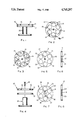
- FIG. 5 is a top view of the upper disk-shaped planar member.
- FIG. 6 is a side view of the upper disk-shaped planar member.
- FIG. 7 is a top view of the lower disk-shaped planar member.
- FIG. 8 is a side view of the lower disk-shaped planar member.
- planar member a lower planar member
- a means for connecting the two together a means to limit rotation of the lower planar member in relation to the upper planar member and a means to secure the specimen stubs within the upper planar member.
- planar members may be of any convenient planar shape, in a preferred embodiment, the upper planar member and lower planar member are in the shape of circular disks.
- Modern specimen stubs used in scanning electron microscopes are in the shape of a thickened circular disk approximately one-half to three-quarters of an inch in diameter and approximately one-half of an inch thick.
- these specimen stubs are first coated with the sample, then placed within an ion beam sputter coating machine to coat the specimen stubs with a very thin coating, i.e. about 30 angstroms in thickness of a heavy metal such as gold or palladium, and finally placed in the scanning electron microscope for analysis.
- a very thin coating i.e. about 30 angstroms in thickness of a heavy metal such as gold or palladium
- the specimen stubs are held within the specimen holder (10) of the instant invention by a two-disk-shaped planar member system, an upper disk (11) and a lower disk (12).
- the upper disk (11) is a circular flat disk containing a plurality of openings (13), with a minimum of six, each opening slightly larger in diameter than the diameter of the specimen stubs. In a preferred embodiment, each of these openings are located an equal distance from the axis of the upper disk (11).
- the diameter of the disk is not crucial and the larger the diameter, the greater the number of specimen stubs that can be held. (See FIG. 5.)
- the size is purely a function of the size of the opening in the ion-beam sputter coating machine to hold the specimen holder. In a preferred embodiment the disks are from 2 to 8 inches in diameter.
- the upper disk also contains apertures (14) in the lip of the disk, equal in number to the number of openings in the upper disk.
- Each of these apertures (14), which run from the outside of the disk to the outside edge of each of the openings (13), are used to secure a specimen stub within the opening (13) by a securing means, such as a screw (15) inserted through the aperture. (See FIG. 2.)
- the lower disk (12) is approximately the same shape as the upper disk (11) with an equal number of openings (16) as those in the upper disk (11) but without apertures in the lip of the lower disk (12). (See FIG. 7.)
- the upper and lower disks may be made of any strong durable material, such as metal or heavy-duty plastic.
- the two disks are secured to each other through of the axis of each disk (17, upper disk axis; 18, lower disk axis) by any normal securing means such as a rivet, screw or other such securing means which will allow the disks to rotate axially in relation to each other.
- the axial rotation device is a bolt (19) running through each disk into a pedestal (24) for the specimen holder. (See FIG. 4.)
- Attached to the upper disk is a means to limit the rotation of the lower disk about its axis in relation to the upper disk.
- attached to the lower surface of the upper disk (11) are at least two pins (20, 21) which project downwardly from the lower surface of the upper disk (see FIG. 6) into arc-shaped trenches (22, 23) contained in the lower disk (12). (See FIGS. 7 and 8.)
- the pins (20, 21) are located an equal distance from the axis of the upper disk (17) and 180 degrees apart. The pins move within the arc-shaped trenches (22, 23) in the lower disk (12).
- the length of these arc-shaped trenches (22, 23) must be sufficient to allow the lower disk (12) to rotate a sufficient number of degrees to prevent a specimen stub placed in the upper disk (11) from dropping out of the specimen holder (10).
- the arc-shaped trenches (22, 23) in the lower disk (12) will allow approximately a 30 degree rotation by the lower disk (12) in relation to the upper disk (11) from the position where the openings in each disk are in line. After rotation, the openings in the upper disk (13) are blocked by the space between the openings of the lower disk (16). (See FIGS. 2 and 3.) This prevents specimen stubs placed in the openings of the upper disk (13) from dropping out of the specimen holder (10).
- the upper and lower disks are provided with a means to secure them to a pedestal (24) which is secured within the ion beam sputter coating machine.
- a pedestal (24) which is secured within the ion beam sputter coating machine.
- an opening is provided in the axis of the upper and lower disk to allow a securing means to penetrate this opening into the pedestal (24).
- the bolt (19) which passes through the axis of the disk to allow axial rotation is secured into the upper portion of the pedestal (24) (See FIG. 4). This pedestal and disk combination is then secured within the ion beam sputter coating machine for coating of the stubs.
- the lower disk (12) is rotated so that specimen stubs are prevented from falling out of the specimen holder when placed within the upper disk (11) (See FIG. 3).
- the specimen stubs to be coated are placed within the specimen holder (10).
- a screw (15) running through an aperture in the lip of the upper disk is tightened to securely hold each stub within the upper disk (11).
- the upper disk and lower disk are then secured to the pedestal by a bolt (19) running through the axis of the upper disk (17) and the axis of the lower disk (18). After the stubs are loaded and secured, the specimen holder and pedestal are secured within the ion beam sputter coating machine.
- the specimen stubs are then coated by a thin coating of a heavy metal, such as gold or palladium, and removed from the ion beam sputter coating machine.
- the lower disk (12) is then rotated to line up the openings of the upper disk (13) and the openings of the lower disk (16) (See FIG. 2).
- the specimen stubs still do not fall from the specimen holder, because of the screws (such as 15) projecting through the apertures in the lip of the upper disk (11), which hold the stubs securely in place.
- that technician unscrews the screw (15) holding each stub and allows it to fall from the specimen holder (10).
- the specimen stub is then placed within the scanning electron microscope by tweezers or other such holding device and analyzed by the electron microscope.
Landscapes
- Chemical & Material Sciences (AREA)
- Analytical Chemistry (AREA)
- Sampling And Sample Adjustment (AREA)
- Analysing Materials By The Use Of Radiation (AREA)
Abstract
Description
Claims (14)
Priority Applications (1)
| Application Number | Priority Date | Filing Date | Title |
|---|---|---|---|
| US07/015,463 US4745297A (en) | 1987-02-17 | 1987-02-17 | Specimen holder for holding specimen stubs to be coated in an ion-beam sputter coating unit |
Applications Claiming Priority (1)
| Application Number | Priority Date | Filing Date | Title |
|---|---|---|---|
| US07/015,463 US4745297A (en) | 1987-02-17 | 1987-02-17 | Specimen holder for holding specimen stubs to be coated in an ion-beam sputter coating unit |
Publications (1)
| Publication Number | Publication Date |
|---|---|
| US4745297A true US4745297A (en) | 1988-05-17 |
Family
ID=21771561
Family Applications (1)
| Application Number | Title | Priority Date | Filing Date |
|---|---|---|---|
| US07/015,463 Expired - Fee Related US4745297A (en) | 1987-02-17 | 1987-02-17 | Specimen holder for holding specimen stubs to be coated in an ion-beam sputter coating unit |
Country Status (1)
| Country | Link |
|---|---|
| US (1) | US4745297A (en) |
Cited By (8)
| Publication number | Priority date | Publication date | Assignee | Title |
|---|---|---|---|---|
| US5033834A (en) * | 1989-01-30 | 1991-07-23 | Micron Technology, Inc. | Microscope specimen mount converter |
| US6872955B1 (en) * | 2003-12-04 | 2005-03-29 | International Business Machines Corporation | SEM sample holder apparatus for implementing enhanced examination of multiple samples |
| US20060231390A1 (en) * | 2005-04-14 | 2006-10-19 | Ravi Mullapudi | Temperature control of pallet in sputtering system |
| US20100025580A1 (en) * | 2008-08-01 | 2010-02-04 | Omniprobe, Inc. | Grid holder for stem analysis in a charged particle instrument |
| KR100989749B1 (en) | 2008-10-28 | 2010-10-26 | 현대제철 주식회사 | Specimen Holder of Scanning Electron Microscope |
| CN101916706A (en) * | 2010-08-03 | 2010-12-15 | 深圳市金洲精工科技股份有限公司 | Sample platform of scanning electronic microscope and scanning electronic microscope |
| ITRM20100143A1 (en) * | 2010-03-30 | 2011-10-01 | Federica Paglietti | ASSEMBLY OF STAMP AND MICROSCOPE STAMP HOLDERS, IN PARTICULAR AN ELECTRONIC SCANNING MICROSCOPE. |
| US20240150889A1 (en) * | 2022-11-09 | 2024-05-09 | Resonac Corporation | Substrate holder, substrate holding method, and film formation apparatus |
Citations (5)
| Publication number | Priority date | Publication date | Assignee | Title |
|---|---|---|---|---|
| US3195502A (en) * | 1962-10-22 | 1965-07-20 | Technicon Company Inc | Tissue receptacle |
| US3245545A (en) * | 1964-09-18 | 1966-04-12 | Wassell Organization Inc | Rotary filing apparatus |
| US3452880A (en) * | 1966-08-30 | 1969-07-01 | Wide Range Ind Inc | Display stand |
| US3461842A (en) * | 1965-11-19 | 1969-08-19 | Ibm | Work holder rack |
| US4485759A (en) * | 1983-01-19 | 1984-12-04 | Multi-Arc Vacuum Systems Inc. | Planetary substrate support apparatus for vapor vacuum deposition coating |
-
1987
- 1987-02-17 US US07/015,463 patent/US4745297A/en not_active Expired - Fee Related
Patent Citations (6)
| Publication number | Priority date | Publication date | Assignee | Title |
|---|---|---|---|---|
| US3195502A (en) * | 1962-10-22 | 1965-07-20 | Technicon Company Inc | Tissue receptacle |
| US3245545A (en) * | 1964-09-18 | 1966-04-12 | Wassell Organization Inc | Rotary filing apparatus |
| US3461842A (en) * | 1965-11-19 | 1969-08-19 | Ibm | Work holder rack |
| US3452880A (en) * | 1966-08-30 | 1969-07-01 | Wide Range Ind Inc | Display stand |
| US4485759A (en) * | 1983-01-19 | 1984-12-04 | Multi-Arc Vacuum Systems Inc. | Planetary substrate support apparatus for vapor vacuum deposition coating |
| US4485759B1 (en) * | 1983-01-19 | 1987-02-10 |
Non-Patent Citations (2)
| Title |
|---|
| "A Container for Handling Small Specimens During Preparation and Examination in the Scanning Electron Microscope (SEM)", Taylor, Journal of Microscopy, vol. 105, Dec. 1975, pp. 335-338. |
| A Container for Handling Small Specimens During Preparation and Examination in the Scanning Electron Microscope (SEM) , Taylor, Journal of Microscopy, vol. 105, Dec. 1975, pp. 335 338. * |
Cited By (11)
| Publication number | Priority date | Publication date | Assignee | Title |
|---|---|---|---|---|
| US5033834A (en) * | 1989-01-30 | 1991-07-23 | Micron Technology, Inc. | Microscope specimen mount converter |
| US6872955B1 (en) * | 2003-12-04 | 2005-03-29 | International Business Machines Corporation | SEM sample holder apparatus for implementing enhanced examination of multiple samples |
| US20060231390A1 (en) * | 2005-04-14 | 2006-10-19 | Ravi Mullapudi | Temperature control of pallet in sputtering system |
| US7479210B2 (en) * | 2005-04-14 | 2009-01-20 | Tango Systems, Inc. | Temperature control of pallet in sputtering system |
| US20100025580A1 (en) * | 2008-08-01 | 2010-02-04 | Omniprobe, Inc. | Grid holder for stem analysis in a charged particle instrument |
| KR100989749B1 (en) | 2008-10-28 | 2010-10-26 | 현대제철 주식회사 | Specimen Holder of Scanning Electron Microscope |
| ITRM20100143A1 (en) * | 2010-03-30 | 2011-10-01 | Federica Paglietti | ASSEMBLY OF STAMP AND MICROSCOPE STAMP HOLDERS, IN PARTICULAR AN ELECTRONIC SCANNING MICROSCOPE. |
| CN101916706A (en) * | 2010-08-03 | 2010-12-15 | 深圳市金洲精工科技股份有限公司 | Sample platform of scanning electronic microscope and scanning electronic microscope |
| CN101916706B (en) * | 2010-08-03 | 2013-09-04 | 深圳市金洲精工科技股份有限公司 | Sample platform of scanning electronic microscope and scanning electronic microscope |
| US20240150889A1 (en) * | 2022-11-09 | 2024-05-09 | Resonac Corporation | Substrate holder, substrate holding method, and film formation apparatus |
| US12612691B2 (en) * | 2022-11-09 | 2026-04-28 | Resonac Hard Disk Corporation | Substrate holder, substrate holding method, and film formation apparatus |
Similar Documents
| Publication | Publication Date | Title |
|---|---|---|
| US4745297A (en) | Specimen holder for holding specimen stubs to be coated in an ion-beam sputter coating unit | |
| US11254553B2 (en) | Decapper and apparatus | |
| US6927400B2 (en) | Sample manipulation system | |
| US7034316B2 (en) | Sample carrier for carrying a sample to be irradiated with an electron beam | |
| JPS59126227A (en) | Method of forming stripe of liquid on slide of microscope and centrifugal turning gear | |
| EP4179126B1 (en) | Apparatus for accommodating an article in a vacuum-coating installation | |
| US5698856A (en) | Specimen holder for electron microscope | |
| EP0547312A1 (en) | Substrate-holding and -turning device for vacuum processes | |
| US6139915A (en) | Cross-section sample staining method | |
| EP0045057B1 (en) | Apparatus for holding disc-shaped substrates | |
| US5033834A (en) | Microscope specimen mount converter | |
| JPH03501307A (en) | Electrodes for use in scanning electron microscopes | |
| JPH02181351A (en) | Bulk sample holder for electron microscope | |
| JPH0817381A (en) | Electron microscope sample equipment | |
| JP3340603B2 (en) | Sample holder for electron microscope | |
| JP5135551B2 (en) | Sample holder | |
| US4909084A (en) | Filament specimen fixture | |
| JPH0953618A (en) | Fixing member | |
| JPS6328519Y2 (en) | ||
| JPH06168689A (en) | Electron microscope sample support method and apparatus | |
| JPH1046338A (en) | Jig for film coating | |
| US5184525A (en) | Mechanism for positioning a carrier | |
| JPH11297251A (en) | Sample mounting tool for transmission electron microscope and method of using the same | |
| JPH01132038A (en) | Mass spectroscope | |
| JPH0259580B2 (en) |
Legal Events
| Date | Code | Title | Description |
|---|---|---|---|
| AS | Assignment |
Owner name: CELANESE CORPORATION, 1211 AVENUE OF THE AMERICAS, Free format text: ASSIGNMENT OF ASSIGNORS INTEREST.;ASSIGNORS:SULLIVAN, WILLIAM H.;JAMIESON, MARJORIE;REEL/FRAME:004670/0624 Effective date: 19870209 Owner name: CELANESE CORPORATION, A CORP. OF DE.,NEW YORK Free format text: ASSIGNMENT OF ASSIGNORS INTEREST;ASSIGNORS:SULLIVAN, WILLIAM H.;JAMIESON, MARJORIE;REEL/FRAME:004670/0624 Effective date: 19870209 |
|
| AS | Assignment |
Owner name: HOECHST CELANESE CORPORATION Free format text: MERGER;ASSIGNORS:AMERICAN HOECHST CORPORATION (INTO);CELANESE CORPORATION;REEL/FRAME:004754/0097 Effective date: 19870227 |
|
| FEPP | Fee payment procedure |
Free format text: PAYOR NUMBER ASSIGNED (ORIGINAL EVENT CODE: ASPN); ENTITY STATUS OF PATENT OWNER: LARGE ENTITY |
|
| REMI | Maintenance fee reminder mailed | ||
| REMI | Maintenance fee reminder mailed | ||
| LAPS | Lapse for failure to pay maintenance fees | ||
| FP | Lapsed due to failure to pay maintenance fee |
Effective date: 19920517 |
|
| STCH | Information on status: patent discontinuation |
Free format text: PATENT EXPIRED DUE TO NONPAYMENT OF MAINTENANCE FEES UNDER 37 CFR 1.362 |