US4724975A - High-pressure structure made of rings with peripheral weldments of reduced thickness - Google Patents
High-pressure structure made of rings with peripheral weldments of reduced thickness Download PDFInfo
- Publication number
- US4724975A US4724975A US06/875,462 US87546286A US4724975A US 4724975 A US4724975 A US 4724975A US 87546286 A US87546286 A US 87546286A US 4724975 A US4724975 A US 4724975A
- Authority
- US
- United States
- Prior art keywords
- shell
- rings
- thickness
- vessel
- weldment
- Prior art date
- Legal status (The legal status is an assumption and is not a legal conclusion. Google has not performed a legal analysis and makes no representation as to the accuracy of the status listed.)
- Expired - Lifetime
Links
Images

Classifications
-
- F—MECHANICAL ENGINEERING; LIGHTING; HEATING; WEAPONS; BLASTING
- F16—ENGINEERING ELEMENTS AND UNITS; GENERAL MEASURES FOR PRODUCING AND MAINTAINING EFFECTIVE FUNCTIONING OF MACHINES OR INSTALLATIONS; THERMAL INSULATION IN GENERAL
- F16J—PISTONS; CYLINDERS; SEALINGS
- F16J12/00—Pressure vessels in general
-
- B—PERFORMING OPERATIONS; TRANSPORTING
- B23—MACHINE TOOLS; METAL-WORKING NOT OTHERWISE PROVIDED FOR
- B23K—SOLDERING OR UNSOLDERING; WELDING; CLADDING OR PLATING BY SOLDERING OR WELDING; CUTTING BY APPLYING HEAT LOCALLY, e.g. FLAME CUTTING; WORKING BY LASER BEAM
- B23K33/00—Specially-profiled edge portions of workpieces for making soldering or welding connections; Filling the seams formed thereby
- B23K33/004—Filling of continuous seams
- B23K33/006—Filling of continuous seams for cylindrical workpieces
-
- F—MECHANICAL ENGINEERING; LIGHTING; HEATING; WEAPONS; BLASTING
- F16—ENGINEERING ELEMENTS AND UNITS; GENERAL MEASURES FOR PRODUCING AND MAINTAINING EFFECTIVE FUNCTIONING OF MACHINES OR INSTALLATIONS; THERMAL INSULATION IN GENERAL
- F16L—PIPES; JOINTS OR FITTINGS FOR PIPES; SUPPORTS FOR PIPES, CABLES OR PROTECTIVE TUBING; MEANS FOR THERMAL INSULATION IN GENERAL
- F16L13/00—Non-disconnectible pipe-joints, e.g. soldered, adhesive or caulked joints
- F16L13/02—Welded joints
-
- Y—GENERAL TAGGING OF NEW TECHNOLOGICAL DEVELOPMENTS; GENERAL TAGGING OF CROSS-SECTIONAL TECHNOLOGIES SPANNING OVER SEVERAL SECTIONS OF THE IPC; TECHNICAL SUBJECTS COVERED BY FORMER USPC CROSS-REFERENCE ART COLLECTIONS [XRACs] AND DIGESTS
- Y10—TECHNICAL SUBJECTS COVERED BY FORMER USPC
- Y10S—TECHNICAL SUBJECTS COVERED BY FORMER USPC CROSS-REFERENCE ART COLLECTIONS [XRACs] AND DIGESTS
- Y10S220/00—Receptacles
- Y10S220/29—Welded seam
Definitions
- This invention relates to circular cylindrical metal shells, especially for high-pressure uses such as for high-pressure vessels and flow conductors, such as penstocks and blast tubes. More particularly, this invention is concerned with an improved high-pressure structure having a circular cylindrical metal shell made of metal rings joined together by weldments and which have peripheral areas of reduced shell thickness at the weldments which permit a reduction in the amount of weld metal deposited while still maintaining sufficient circumferential or hoop stress strength.
- Circular cylindrical metal shells are widely used in large civil engineering projects as, for example, penstocks in dam projects, blast tubes and in the fabrication of high-pressure structures, including vessels.
- One type of high-pressure vessel which is suitably employed in many industrial processes has a circular cylindrical shell body, which is generally positioned horizontally or vertically, and end closures which can be hemispherical, elliptical or conical shells or even be flat ends.
- Many pressure vessels of the described shape are shop fabricated and then transported to the site for erection. However, the large size and weight of some such high-pressure vessels prohibits shop fabrication so field fabrication at the site is necessary.
- the cylindrical shell is generally made from metal rings which are joined together in consecutive order by weldments which connect abutting edges of adjacent rings. Because the metal rings often are made of metal plates 3 to 12 inches or more thick, and have a diameter of 3 to 30 feet or more, the weldments used to join the rings are time consuming and costly to make. Furthermore, 8 inch thick rings are generally the maximum joined together in field or site fabrication. While vessels greater than 8" thick can be site erected, vessel construction gets more complicated and therefore more costly for vessels greater than 8" thick.
- a circular cylindrical solid walled metal shell with inner and outer surfaces and being capable of withstanding an internal pressure for which the shell is designed, the cylindrical shell comprising a series of consecutive metal rings of essentially equal maximum thickness positioned in axial arrangement with abutting ends of adjacent rings being joined together by a weldment; and the axial length of the cylindrical shell portion comprising the abutting end portions of adjacent rings, and the weldment joining the abutting ends together, having a reduced thickness which is not more than about 0.90 of the maximum thickness of the rings.
- the described circular cylindrical shell can be open or closed at one or both ends. It can be used as a flow conductor, such as a penstock, blast tube, or for similar uses.
- a solid walled high-pressure structure having a circular cylindrical shell with inner and outer surfaces and end closures and being capable of withstanding an internal pressure for which the structure is designed
- the cylindrical shell comprises a series of consecutive metal rings of essentially equal maximum thickness positioned in axial arrangement with abutting ends of adjacent rings being joined together by a weldment; and the axial length of the cylindrical shell portion comprising the abutting end portions of adjacent rings, and the weldment joining the abutting ends together, has a reduced thickness which is not more than about 0.90 of the maximum thickness of the rings.
- the reduced thickness at the joints in general, should not be less than 0.50, and desirably 0.67, of the maximum thickness of the rings.
- each ring be 2.5 times the square root of the cylindrical shell internal radius times the maximum thickness of the cylindrical shell. This sizing of the rings assures that the grooves or areas of reduced thickness are not located too close together to provide the desired shell design strength.
- Only the internal surface, or only the external surface, of the cylindrical shell can be a substantially smooth cylindrical surface at the weldment joining abutting ends of adjacent rings.
- the reduced thickness of the axial length of the cylindrical shell can be located radially inward from the outer surface of the shell and radially outward from the inner surface of the shell.
- the reduced thickness area at the weldment can be located inwardly from both the outer and inner surfaces of the rings and shell.
- a shell can be fabricated having some of the joints smooth on the inside surface and some joints smooth on the outside surface.
- some of the areas of reduced thickness at the weldments can be only inside, and some only outside, the shell.
- the area of reduced thickness can define a peripheral groove extending around the outside of the structure with the groove having a maximum width axial of the structure adequate to deposit at least a portion of the weldment from outside the shell.
- the area of reduced thickness can also define a peripheral groove extending around the inside of the structure, with the groove having a maximum width axial of the structure adequate to deposit at least a portion of the weldment from inside the shell.
- the area of reduced thickness can be defined by peripheral grooves on both sides thereof so that one groove is on the outside, and another groove is on the inside, of the shell.
- the shape of the peripheral groove can vary and it can be symmetrical or asymmetrical. It can have a flat or curved bottom when viewed in section parallel to the vessel longitudinal axis and, in addition, the sides of the groove when similarly viewed can be sloped in a curved manner or have tapered surfaces.
- each ring wall from its thickest part to its thinnest part at the weldment must be able to withstand the design maximum circumferential or hoop force for which the vessel is to be used.
- the thickness of the rings generally will be in the range of 1 to 20 inches, and usually will be at least 3 inches, and desirably 5 inches, thick for best utilization of the advantages of the invention.
- shell rings 12 inches thick can be joined together conveniently because the weldments need only be about 6 to 10.8 inches thick at the peripheral groove at each of the weldments.
- the reduced thickness area at the groove will create higher stress locally in the circumferential direction. However, since the total amount of material removed is small when compared to the remaining material, the ultimate capacity will not be significantly reduced. As the thinned area tries to stretch due to the higher stress, it will be restrained by the thicker material on either side of it. Therefore, some of the pressure loading in the thin area will be shifted to the thicker material. Bursting for ductile materials will not occur until all the material has fully yielded and is at the ultimate capacity of the material.
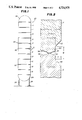
- FIG. 1 is an elevational view of a vertical pressure vessel having a shell fabricated according to the invention
- FIG. 2 is an enlarged sectional view of the joint portion circled in FIG. 1 before the weldment is deposited;
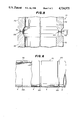
- FIG. 3 is a sectional view of the shell of FIG. 1 having the joint area of reduced thickness in the shell external surface;
- FIG. 4 is a sectional view of a shell having a joint with the area of reduced thickness in the shell internal surface
- FIG. 5 is a sectional view of a shell having a joint in which the area of reduced thickness is located radially inward from the shell inner and outer surfaces;
- FIG. 6 is an elevational view, partially in section, of an open-ended shell according to the invention suitable for use as a penstock, blast tube or the like.
- the vertical solid walled high-pressure vessel 20 has a vertical shell or body 22, a hemispherical bottom closure 24 and a hemispherical top closure 26.
- the vessel is supported by legs 28.
- the vessel shell or body 22 is fabricated from a series of ten consecutive metal rings A to J of essentially equal maximum thickness positioned in axial arrangement with abutting ends of adjacent rings being joined together by a weldment 30 (FIG. 3).
- FIG. 2 The adjacent abutting edges of rings E and F before weldment 30 is deposited is illustrated by FIG. 2. It should be understood that all the abutting adjacent edges of all the rings A to J are similarly shaped before welding.
- the maximum width of the area of fully reduced thickness 100 at the joint is shown in FIG. 2 as W.
- the maximum depth of the area of reduced thickness 100 is shown in FIG. 2 as X.
- the weldment joining together the abutting edges of the rings E and F will have the thickness Y.
- X plus Y equals the radial thickness Z of rings E and F.
- the thickness Y which equals the thickness of the weldment (FIG. 3) has a reduced thickness which is not more than about 0.90 of the ring thickness Z.
- each ring E, F is tapered outwardly 50, 52.
- the adjacent abutting edges of rings E and F are beveled 36, 38, 40, 42 to provide space for deposit of weld metal through the full thickness of the joint.
- Such beveled surfaces can have any suitable shape.
- the thickness Z of the rings used to fabricate shell 22 may be increased in thickness above the thickness V used for rings where the joints are made the full thickness of the rings to reinforce the joint area surrounding the area of reduced thickness.
- Z can be about 1 to 1.2 times the thickness V.
- FIG. 4 The second embodiment of the invention illustrated by FIG. 4 is similar to that shown in FIGS. 1 to 3. Rings E1 and F1 in FIG. 4 are comparable to rings E and F in FIGS. 1 to 3. The embodiment of FIG. 4, however, will be seen to have the area of reduced thickness 100 on the inside of the shell rather than on the outside as shown in FIGS. 1 to 3.
- FIG. 5 The third embodiment of the invention is illustrated by FIG. 5.
- an area of reduced thickness 102 is located radially inward from the outer surface, and an area of reduced thickness 104 is located radially outward from the inner surface of the rings E2, F2 of shell 22.
- rings E2, F2 are like rings E, F and E1, F1 except for the adjacent edge portions of reduced thickness.
- FIG. 6 illustrates the shell 22 fabricated as described in connection with FIGS. 1 to 3 but with each end open so that it can be used as a flow conductor, such as a penstock, blast tube or for a similar purpose.
- a pressure vessel is fabricated as illustrated by FIGS. 1 to 3 for a design pressure of 1800 psig and design temperature of 850° F. using SA-387, Grade 22, Class 2 steel.
- the vessel is designed to meet the code requirements of ASME Section VIII, Division 2, para. AD-201.
- the thickness V of the rings A-J for full thickness weldments is 9 inches.
- the joint thickness Y can be reduced to 6 inches or less, with W equal to 4.5 inches.
- rings can be used with Z equal to more than 9 inches.
- Z equal to 9.61"
- the extra thickness adjacent to the joint provides for full area replacement within the square root of the product of the radius and the thickness.
- the final dimensions of Z and Y as well as the slope and location of the reduction levels 36, 38, 40, 42 are to be determined by detailed stress analysis per the Appendix 4 criteria of ASME Section VIII, Division 2 or other similar design procedures. A variety of acceptable configurations can be provided. The actual configuration utilized will be determined by an overall cost analysis of the material costs, shop labor and field labor for a particular structure.
Landscapes
- Engineering & Computer Science (AREA)
- General Engineering & Computer Science (AREA)
- Mechanical Engineering (AREA)
- Pressure Vessels And Lids Thereof (AREA)
- Butt Welding And Welding Of Specific Article (AREA)
- Filling Or Discharging Of Gas Storage Vessels (AREA)
Abstract
Description
Claims (20)
Priority Applications (6)
| Application Number | Priority Date | Filing Date | Title |
|---|---|---|---|
| US06/875,462 US4724975A (en) | 1986-06-18 | 1986-06-18 | High-pressure structure made of rings with peripheral weldments of reduced thickness |
| DE3639348A DE3639348C2 (en) | 1986-06-18 | 1986-11-18 | High pressure resistant metal cover |
| CA000523550A CA1272690A (en) | 1986-06-18 | 1986-11-21 | High-pressure structure made of rings with peripheral weldments of reduced thickness |
| ZA868954A ZA868954B (en) | 1986-06-18 | 1986-11-26 | High-pressure structure made of rings with peripheral weldments of reduced thickness |
| FR8616916A FR2600392A1 (en) | 1986-06-18 | 1986-12-03 | CIRCULAR CYLINDRICAL METAL SHELL, AND CONTAINER COMPRISING SAID SHELL |
| JP61295711A JPS631860A (en) | 1986-06-18 | 1986-12-11 | Metallic shell with circular cylindrical solid wall and high-pressure vessel including said shell |
Applications Claiming Priority (1)
| Application Number | Priority Date | Filing Date | Title |
|---|---|---|---|
| US06/875,462 US4724975A (en) | 1986-06-18 | 1986-06-18 | High-pressure structure made of rings with peripheral weldments of reduced thickness |
Publications (1)
| Publication Number | Publication Date |
|---|---|
| US4724975A true US4724975A (en) | 1988-02-16 |
Family
ID=25365850
Family Applications (1)
| Application Number | Title | Priority Date | Filing Date |
|---|---|---|---|
| US06/875,462 Expired - Lifetime US4724975A (en) | 1986-06-18 | 1986-06-18 | High-pressure structure made of rings with peripheral weldments of reduced thickness |
Country Status (6)
| Country | Link |
|---|---|
| US (1) | US4724975A (en) |
| JP (1) | JPS631860A (en) |
| CA (1) | CA1272690A (en) |
| DE (1) | DE3639348C2 (en) |
| FR (1) | FR2600392A1 (en) |
| ZA (1) | ZA868954B (en) |
Cited By (17)
| Publication number | Priority date | Publication date | Assignee | Title |
|---|---|---|---|---|
| US5284267A (en) * | 1992-02-21 | 1994-02-08 | Pas, Inc. | Fuel injection apparatus for vehicles |
| US5429268A (en) * | 1993-03-05 | 1995-07-04 | Tri-Fuels, Inc. & The Rosalind Hale Revocable Trust | Tubular above ground gas storage vessel |
| US5697511A (en) * | 1996-09-27 | 1997-12-16 | Boeing North American, Inc. | Tank and method of fabrication |
| WO1998016749A1 (en) * | 1996-10-11 | 1998-04-23 | Kimball Physics, Inc. | Perimeter weld flanges |
| US5908134A (en) * | 1993-03-05 | 1999-06-01 | The Rosalind Hale Revocable Trust, Uta George Carl Hale, Trustee | Tubular above ground gas storage vessel |
| US6012598A (en) * | 1997-06-09 | 2000-01-11 | The Columbiana Boiler Company | Freight container |
| US20060090500A1 (en) * | 2003-12-19 | 2006-05-04 | Sienel Tobias H | Vapor compression systems using an accumulator to prevent over-pressurization |
| US7163121B1 (en) * | 1999-07-14 | 2007-01-16 | Swales & Associates, Inc. | High temperature isostatic pressure bonding of hollow beryllium pressure vessels using a bonding flange |
| CN100543349C (en) * | 2006-12-29 | 2009-09-23 | 陈阵 | Multiunit tube joint and processing method thereof |
| CN101934420A (en) * | 2010-08-18 | 2011-01-05 | 中信重工机械股份有限公司 | Method for welding conical mill |
| US20120193244A1 (en) * | 2009-09-22 | 2012-08-02 | Gian Luigi Cola | Gas cylinder |
| US20140000180A1 (en) * | 2011-03-23 | 2014-01-02 | Northcone Ab | Yielding Post of Thin Sheet Metal and Method of Arranging Street Lighting |
| US20140016994A1 (en) * | 2012-07-06 | 2014-01-16 | Snecma | Parts assembled through friction welding |
| US20160039043A1 (en) * | 2014-08-06 | 2016-02-11 | Rolls-Royce Plc | Rotary friction welding |
| JP2017078580A (en) * | 2015-10-19 | 2017-04-27 | 株式会社神戸製鋼所 | Radioactive material transportation storage container, and manufacturing method of radioactive material transportation storage container |
| CN108599063A (en) * | 2018-05-21 | 2018-09-28 | 深圳市沃尔核材股份有限公司 | The connection method and connection structure of a kind of wind tower with two tube type bus |
| US20230241724A1 (en) * | 2022-01-28 | 2023-08-03 | Samsung Engineering Co., Ltd. | Weld groove forming method and hollow article |
Families Citing this family (2)
| Publication number | Priority date | Publication date | Assignee | Title |
|---|---|---|---|---|
| US20080087665A1 (en) * | 2006-10-13 | 2008-04-17 | Columbiana Boiler Company, Llc | Freight container |
| US20140083191A1 (en) * | 2011-06-01 | 2014-03-27 | Toyota Jidosha Kabushiki Kaisha | Joint structure by welding and welding quality inspection method thereof |
Citations (5)
| Publication number | Priority date | Publication date | Assignee | Title |
|---|---|---|---|---|
| US1655931A (en) * | 1926-03-13 | 1928-01-10 | Smith Corp A O | Oil-refining still and method of making the same by electric-arc welding |
| US1961117A (en) * | 1932-06-04 | 1934-05-29 | Linde Air Prod Co | Method of welding copper alloys, particularly wrought copper alloys |
| US2179774A (en) * | 1935-12-07 | 1939-11-14 | Smith Corp A O | Welded pressure vessel |
| US2233455A (en) * | 1938-05-21 | 1941-03-04 | Smith Corp A O | Method of welding |
| US3270906A (en) * | 1963-09-25 | 1966-09-06 | Chemical Construction Corp | Closure for pressure vessels |
Family Cites Families (7)
| Publication number | Priority date | Publication date | Assignee | Title |
|---|---|---|---|---|
| CH166852A (en) * | 1933-02-10 | 1934-01-31 | Buss Ag | Process to reduce the strength of the V and X butt welds on circumferential seams of hollow bodies. |
| US2391747A (en) * | 1942-08-26 | 1945-12-25 | Babcock & Wilcox Co | Penstock and method of fabricating penstocks |
| GB1253250A (en) * | 1968-09-24 | 1971-11-10 | ||
| JPS4827215U (en) * | 1971-08-05 | 1973-04-02 | ||
| JPS5118950A (en) * | 1974-08-07 | 1976-02-14 | Babcock Hitachi Kk | Enshinchuzokanno tsukiawaseyosetsuhoho |
| JPS5572977A (en) * | 1978-11-28 | 1980-06-02 | Babcock Hitachi Kk | Welded joint structure of centrifugal casted pipe |
| DE3507010A1 (en) * | 1985-02-28 | 1986-08-28 | Fa. Eisenbau Krämer mbH, 5912 Hilchenbach | Method for the production of, in particular, thick-walled tubes |
-
1986
- 1986-06-18 US US06/875,462 patent/US4724975A/en not_active Expired - Lifetime
- 1986-11-18 DE DE3639348A patent/DE3639348C2/en not_active Expired - Fee Related
- 1986-11-21 CA CA000523550A patent/CA1272690A/en not_active Expired - Lifetime
- 1986-11-26 ZA ZA868954A patent/ZA868954B/en unknown
- 1986-12-03 FR FR8616916A patent/FR2600392A1/en active Pending
- 1986-12-11 JP JP61295711A patent/JPS631860A/en active Pending
Patent Citations (5)
| Publication number | Priority date | Publication date | Assignee | Title |
|---|---|---|---|---|
| US1655931A (en) * | 1926-03-13 | 1928-01-10 | Smith Corp A O | Oil-refining still and method of making the same by electric-arc welding |
| US1961117A (en) * | 1932-06-04 | 1934-05-29 | Linde Air Prod Co | Method of welding copper alloys, particularly wrought copper alloys |
| US2179774A (en) * | 1935-12-07 | 1939-11-14 | Smith Corp A O | Welded pressure vessel |
| US2233455A (en) * | 1938-05-21 | 1941-03-04 | Smith Corp A O | Method of welding |
| US3270906A (en) * | 1963-09-25 | 1966-09-06 | Chemical Construction Corp | Closure for pressure vessels |
Cited By (23)
| Publication number | Priority date | Publication date | Assignee | Title |
|---|---|---|---|---|
| US5284267A (en) * | 1992-02-21 | 1994-02-08 | Pas, Inc. | Fuel injection apparatus for vehicles |
| US5429268A (en) * | 1993-03-05 | 1995-07-04 | Tri-Fuels, Inc. & The Rosalind Hale Revocable Trust | Tubular above ground gas storage vessel |
| US5908134A (en) * | 1993-03-05 | 1999-06-01 | The Rosalind Hale Revocable Trust, Uta George Carl Hale, Trustee | Tubular above ground gas storage vessel |
| US5697511A (en) * | 1996-09-27 | 1997-12-16 | Boeing North American, Inc. | Tank and method of fabrication |
| WO1998016749A1 (en) * | 1996-10-11 | 1998-04-23 | Kimball Physics, Inc. | Perimeter weld flanges |
| US6270045B1 (en) | 1996-10-11 | 2001-08-07 | Kimball Physics, Inc. | Perimeter weld flanges |
| US6012598A (en) * | 1997-06-09 | 2000-01-11 | The Columbiana Boiler Company | Freight container |
| US7163121B1 (en) * | 1999-07-14 | 2007-01-16 | Swales & Associates, Inc. | High temperature isostatic pressure bonding of hollow beryllium pressure vessels using a bonding flange |
| US20060090500A1 (en) * | 2003-12-19 | 2006-05-04 | Sienel Tobias H | Vapor compression systems using an accumulator to prevent over-pressurization |
| CN100543349C (en) * | 2006-12-29 | 2009-09-23 | 陈阵 | Multiunit tube joint and processing method thereof |
| US8608013B2 (en) * | 2009-09-22 | 2013-12-17 | Faber Industrie S.P.A. | Gas cylinder |
| US20120193244A1 (en) * | 2009-09-22 | 2012-08-02 | Gian Luigi Cola | Gas cylinder |
| CN101934420A (en) * | 2010-08-18 | 2011-01-05 | 中信重工机械股份有限公司 | Method for welding conical mill |
| US20140000180A1 (en) * | 2011-03-23 | 2014-01-02 | Northcone Ab | Yielding Post of Thin Sheet Metal and Method of Arranging Street Lighting |
| US20140016994A1 (en) * | 2012-07-06 | 2014-01-16 | Snecma | Parts assembled through friction welding |
| US9321125B2 (en) * | 2012-07-06 | 2016-04-26 | Snecma | Parts assembled through friction welding |
| US20160039043A1 (en) * | 2014-08-06 | 2016-02-11 | Rolls-Royce Plc | Rotary friction welding |
| US9791075B2 (en) * | 2014-08-06 | 2017-10-17 | Rolls-Royce Plc | Rotary friction welding |
| JP2017078580A (en) * | 2015-10-19 | 2017-04-27 | 株式会社神戸製鋼所 | Radioactive material transportation storage container, and manufacturing method of radioactive material transportation storage container |
| CN108599063A (en) * | 2018-05-21 | 2018-09-28 | 深圳市沃尔核材股份有限公司 | The connection method and connection structure of a kind of wind tower with two tube type bus |
| CN108599063B (en) * | 2018-05-21 | 2024-01-05 | 深圳市沃尔核材股份有限公司 | Connection method and connection structure of two tubular buses for wind power tower |
| US20230241724A1 (en) * | 2022-01-28 | 2023-08-03 | Samsung Engineering Co., Ltd. | Weld groove forming method and hollow article |
| US11897058B2 (en) * | 2022-01-28 | 2024-02-13 | Samsung Engineering Co., Ltd. | Weld groove forming method and hollow article |
Also Published As
| Publication number | Publication date |
|---|---|
| JPS631860A (en) | 1988-01-06 |
| ZA868954B (en) | 1987-08-26 |
| CA1272690A (en) | 1990-08-14 |
| FR2600392A1 (en) | 1987-12-24 |
| DE3639348C2 (en) | 1998-12-10 |
| DE3639348A1 (en) | 1987-12-23 |
Similar Documents
| Publication | Publication Date | Title |
|---|---|---|
| US4724975A (en) | High-pressure structure made of rings with peripheral weldments of reduced thickness | |
| US4307812A (en) | Freight container for flowable substances | |
| AU652875B2 (en) | A tank having an intermediate wall | |
| US2503191A (en) | Method of forming tanks of spherical configuration | |
| US3793145A (en) | Nuclear containment vessel and method of making same | |
| US1933772A (en) | Thick walled pressure vessel | |
| US3889836A (en) | Method and means for constructing large tanks | |
| JPH026060A (en) | Method of fixing tube to thick wall member such as tube carrier drum of reactor vessel through welding | |
| US3139265A (en) | Turbine and pump runner | |
| US4398646A (en) | Multi-layered vessel with discontinuity neutralizing area | |
| US5035355A (en) | Method for the production of a warp beam, and warp beam so produced | |
| US3425380A (en) | Tank and method of manufacturing same | |
| US6426986B1 (en) | Forged nozzle shell course for a pressure vessel | |
| US7011343B1 (en) | Socket-welded pipe joint | |
| US3584657A (en) | Flange for multilayer container | |
| US3344509A (en) | Method for the explosive section forming of vessels | |
| US4010864A (en) | Multilayer pressure vessel | |
| KR20030085025A (en) | Connecting flange for tubular components | |
| US3397443A (en) | Method for the manufacture of cylindrical containers particularly so-called cisterns | |
| US3342209A (en) | Unsymmetrical connection-piece nozzle | |
| US3587905A (en) | Pressure vessel | |
| GB2075145A (en) | Fracture arrestor for a pipeline | |
| EP0029741A2 (en) | A method of forming a valve body section with integral hub and making a valve body using such body sections | |
| CA1069023A (en) | Stay ring for a spiral casing for a rotary hydraulic machine | |
| US4570813A (en) | Connection anchor for liner of cast iron pressure tank |
Legal Events
| Date | Code | Title | Description |
|---|---|---|---|
| AS | Assignment |
Owner name: CBI INDUSTRIES, INC., 800 JORIE BOULEVARD, OAK BRO Free format text: ASSIGNMENT OF ASSIGNORS INTEREST.;ASSIGNOR:LEVENTRY, SAMUEL C.;REEL/FRAME:004592/0878 Effective date: 19860611 Owner name: CBI INDUSTRIES, INC., A CORP. OF DE.,ILLINOIS Free format text: ASSIGNMENT OF ASSIGNORS INTEREST;ASSIGNOR:LEVENTRY, SAMUEL C.;REEL/FRAME:004592/0878 Effective date: 19860611 |
|
| AS | Assignment |
Owner name: CBI RESEARCH CORPORATION, PLAINFIELD, ILL. A CORP. Free format text: ASSIGNMENT OF ASSIGNORS INTEREST.;ASSIGNOR:CBI INDUSTRIES, INC., A DE CORP.;REEL/FRAME:004723/0621 Effective date: 19870601 |
|
| STCF | Information on status: patent grant |
Free format text: PATENTED CASE |
|
| FPAY | Fee payment |
Year of fee payment: 4 |
|
| FEPP | Fee payment procedure |
Free format text: PAYOR NUMBER ASSIGNED (ORIGINAL EVENT CODE: ASPN); ENTITY STATUS OF PATENT OWNER: LARGE ENTITY |
|
| FPAY | Fee payment |
Year of fee payment: 8 |
|
| AS | Assignment |
Owner name: CHICAGO BRIDGE & IRON COMPANY (DELAWARE), ILLINOIS Free format text: ASSIGNMENT OF ASSIGNORS INTEREST;ASSIGNOR:CBI RESEARCH CORPORATION;REEL/FRAME:008366/0920 Effective date: 19970204 |
|
| FPAY | Fee payment |
Year of fee payment: 12 |