US4719447A - Analog-to-digital converter with push-pull input signal configuration - Google Patents
Analog-to-digital converter with push-pull input signal configuration Download PDFInfo
- Publication number
- US4719447A US4719447A US07/012,755 US1275587A US4719447A US 4719447 A US4719447 A US 4719447A US 1275587 A US1275587 A US 1275587A US 4719447 A US4719447 A US 4719447A
- Authority
- US
- United States
- Prior art keywords
- comparators
- analog
- signal
- signals
- inputs
- Prior art date
- Legal status (The legal status is an assumption and is not a legal conclusion. Google has not performed a legal analysis and makes no representation as to the accuracy of the status listed.)
- Expired - Fee Related
Links
- 230000000052 comparative effect Effects 0.000 claims description 5
- 239000004020 conductor Substances 0.000 description 7
- 239000000758 substrate Substances 0.000 description 6
- 238000010586 diagram Methods 0.000 description 4
- 230000000295 complement effect Effects 0.000 description 2
- 238000010276 construction Methods 0.000 description 2
- 238000002347 injection Methods 0.000 description 2
- 239000007924 injection Substances 0.000 description 2
- 238000012886 linear function Methods 0.000 description 2
- 241000283725 Bos Species 0.000 description 1
- 230000003247 decreasing effect Effects 0.000 description 1
- 238000004519 manufacturing process Methods 0.000 description 1
- 238000005070 sampling Methods 0.000 description 1
- 230000001629 suppression Effects 0.000 description 1
Images


Classifications
-
- H—ELECTRICITY
- H03—ELECTRONIC CIRCUITRY
- H03M—CODING; DECODING; CODE CONVERSION IN GENERAL
- H03M1/00—Analogue/digital conversion; Digital/analogue conversion
- H03M1/06—Continuously compensating for, or preventing, undesired influence of physical parameters
- H03M1/08—Continuously compensating for, or preventing, undesired influence of physical parameters of noise
-
- H—ELECTRICITY
- H03—ELECTRONIC CIRCUITRY
- H03M—CODING; DECODING; CODE CONVERSION IN GENERAL
- H03M1/00—Analogue/digital conversion; Digital/analogue conversion
- H03M1/12—Analogue/digital converters
- H03M1/34—Analogue value compared with reference values
- H03M1/36—Analogue value compared with reference values simultaneously only, i.e. parallel type
- H03M1/361—Analogue value compared with reference values simultaneously only, i.e. parallel type having a separate comparator and reference value for each quantisation level, i.e. full flash converter type
Definitions
- the present invention relates to analog-to-digital converters and, in particular, to a parallel or "flash" analog-to-digital converter that provides a digital word which represents with high precision the amplitude of an analog input signal.
- One type of analog-to-digital converter commonly referred to as a parallel or “flash” analog-to-digital converter, employs a group of voltage comparators, each of which has an analog signal input and a voltage reference input.
- the analog signal inputs of the comparators are electrically connected together to provide a single-ended input configuration.
- the reference voltage inputs receive reference voltages from a series-connected resistor network.
- the comparators provide output signals which form a "thermometer" code corresponding to the amplitude of the input signal.
- the thermometer code is then encoded into a digital signal having a binary format.
- An analog-to-digital converter is fabricated typically as an integrated circuit.
- a flash analog-to-digital converter of the integrated circuit type that employs a single-ended input configuration uses the substrate as the primary return path for the input signal currents.
- the application of the same analog input signal to all of the comparators causes capacitive injection of substantial noise currents into the substrate. These noise currents can cause unacceptable levels of cross talk among the different circuits comprising portions of and the signals flowing within the integrated circuit.
- the presence of noise currents reduces the precision of the analog-to-digital converter.
- Significant amounts of return signal currents also flow through the reference voltage and power supply circuitry. Consequently, to ensure proper operation of the circuit, it is necessary that each of the return current paths have a low impedance connection to the analog input signal source ground. Such low impedance return connections are, however, difficult to achieve.
- An object of the present invention is to provide a parallel or "flash" analog-to-digital converter that produces a digital output word which corresponds with high precision to the amplitude of an analog input signal.
- Another object of this invention is to provide such an analog-to-digital converter that has improved suppression of noise currents.
- a further object of this invention is to provide such an analog-to-digital converter in a configuration that reduces or eliminates the need for low impedance return current connections to the analog input signal source ground.
- Still another object of this invention is to provide such an analog-to-digital converter that is suitable for fabrication as an integrated circuit.
- the present invention constitutes an analog-to-digital converter which receives an analog signal and develops input signals of equal magnitude but opposite polarity that are applied in push-pull fashion to different sets of comparators.
- the circuit includes input circuitry for developing and processing the input signals; first and second separate sets of comparators, each comparator having an analog input, a reference input, and an output; a common series-connected resistor network; and output circuitry such as two encoders and a digital adder.
- the input circuitry receives the analog input signal and develops suitable first and second analog input signals of equal magnitude but opposite polarity.
- the first input signal is applied to the analog inputs of the first set of comparators, and the second input signal is applied to the analog inputs of the second set of comparators.
- the common resistor network provides a series of different reference voltages which are applied to the reference inputs of the comparators.
- Each comparator provides an output signal in a high or low voltage state representing the comparative relationship of the analog input signal and reference voltage present on its inputs.
- the outputs of the comparators in each set form separate digital thermometer codes corresponding to the voltage level of the analog signal.
- the encoders detect the number of outputs in the same voltage state (e.g. high voltage) provided by each set of comparators and develop binary signals corresponding to these numbers which are summed by the adder to generate the desired binary output word.
- analog and reference inputs to one of the sets of comparators are noninverting and inverting, respectively, while the analog and reference inputs to the other set are inverting and noninverting, respectively.
- a voltage source provides a constant voltage that offsets the analog input signal applied to one of the sets of comparators. This voltage offset facilitates the use of a simplified common resistor network that can be constructed with fewer resistors, and, consequently, with fewer electrical connections, than those required in the other preferred embodiment.
- the analog-to-digital converter of the present invention confines the injection of equal and opposite noise currents to small areas in the integrated circuit. This reduces cross talk among other signals flowing through the integrated circuit. This circuit also reduces the net noise current introduced into the substrate and power supply connections and, as a consequence, reduces or eliminates the need for very low impedance connections between the signal source and the ground conductors, the reference signal source, and the power supply. The reduction in noise currents provides an analog-to-digital converter of high precision.
- FIG. 1 is a schematic diagram of the electrical circuitry for a preferred embodiment of the analog-to-digital converter of the present invention.
- FIG. 2 is a diagram illustrating the operation of the comparators of the converter circuit of FIG. 1.
- FIG. 3 is a graph which plots the number of comparators of the converter circuit of FIG. 1 in similar output states as a function of analog input voltage.
- FIG. 4 is a schematic diagram of the electrical circuitry for an alternative preferred embodiment of the analog-to-digital converter of the present invention.
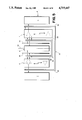
- FIG. 5 is a diagram of a layout for the electrical circuitry of the present invention implemented as an integrated circuit.
- the general operation of converter circuit A of the present invention may be outlined as follows.
- the converter circuit A receives an analog input signal at an input terminal B and provides a corresponding binary output word at an output terminal C.
- the analog input signal is supplied through an inverter D to a set E of comparators and directly to a set F of comparators.
- the output signal of inverter D and the analog input signal are of equal magnitude but opposite polarity.
- These signals may undergo optional processing by separate signal processors G 1 and G 2 before they are applied to the comparators.
- the comparators in both sets E and F are furnished with reference voltages from a common series-connected resistor network H.
- the comparators in sets E and F provide separate digital thermometer code outputs to respective encoders I and J.
- the encoders I and J provide binary output signals corresponding to the number of comparator outputs supplied to them in a similar (e.g., high voltage) state.
- the output signals from the encoders I and J are summed by an adder K to form the desired binary output word at the output terminal C.
- the inverter D receives an instantaneously variable continuous analog input signal V A on a line 10 from the terminal B and provides on a line 12 a signal -V A .
- Each of the signal procesors G 1 and G 2 may comprise, for example, an optional sample-and-hold circuit which samples at regular time intervals the signal applied to its input and supplies a periodically variable output coresponding to the amplitude of the input signal at the start of each sampling period.
- the signal processor G 1 receiving the signal V A provides an output signal V 1 on a line 14 to the comparators of the set F.
- the signal processor G 2 receiving the signal-V A provides an output signal V 2 on a line 18 to the comparators of the set E.
- the seven voltage comparators provide, by way of example only, a 3-bit converter circuit A. Skilled persons would appreciate that analog-to-digital converters having a different number of output bits can be implemented in accordance with the present invention.
- the set E includes the comparators 20e-20g, and the set F includes the comparators 20a-20d.
- the comparators 20e-20g in set E have respective analog inputs 22e-22g, reference inputs 24e-24g, and logic outputs 30e-30g.
- the comparators 20a-20d in set F have respective analog inputs 22a-22d, reference inputs 24a-24d, and logic outputs 30a-30d.
- the comparators 20a-20g compare the signals provided at their analog inputs 22a-22g with the reference voltage signals provided at their reference inputs 24a-24g, and each comparator 20a-20g provides on its respective output 30a-30g a logic signal representative of the relationship between the voltage levels at its inputs.
- analog inputs 22e-22g are the inverting inputs of the respective comparators 20e-20g and are electrically connected to the line 18 which forms a common line that delivers the signal V 2 to all the comparators in set E.
- Reference inputs 24e-24g are the noninverting inputs of the respective comparators 20e-20g and are electrically connected to and receive different DC reference voltages from the junction nodes 26e-26g of the resistor network H which will be described hereinafter in greater detail.
- Each of the comparators 20e-20g in the set E provides a logic 1 or high voltage output signal whenever the voltage of its analog input signal V 2 is less than the reference voltage from the one of junction nodes 26e-26g to which it is connected, and otherwise provides a logic 0 or low voltage output signal.
- analog inputs 22a-22d are the noninverting inputs of the respective comparators 20a-20d and are electrically connected to the line 14 which forms a common line that delivers the signal V 1 to all the comparators in set F.
- Reference inputs 24a-24d are the inverting inputs of the respective comparators 20a-20d and are electrically connected to and receive different DC reference voltages from the junction nodes 26a-26d of the resistor network H.
- Each of the comparators 20a-20d in the set F provides a logic 1 or high voltage output signal whenever the voltage of its analog input signal V 1 exceeds the reference voltage from the one of junction nodes 26a-26d to which it is connected, and otherwise provides a logic 0 or low voltage. output signal.
- the resistor network H provides seven junction nodes 26a-26g to which the reference inputs of the respective comparators 20a-20g are individually connected.
- the above values of the DC supply voltages and resistors are presented by way of example only and can be changed to accommodate a particular circuit application.
- the comparators 20a-20g have high impedance inputs, the voltage drops across the resistors 28a and 28h are approximately equal to 0.5 volt and the voltage drops across the resistors 28b-28g are approximately equal to 1.0 volt.
- the resi-stor network H together with DC voltages V REF and -V REF applied to the terminals 15 and 25 provide, therefore, the reference voltages -3 V, -1 V, +1 V, and +3 V at the respective junction nodes 26a-26d and the reference voltages +2 V, 0 V, and -2 V at the respective junction nodes 26e-26g, respectively.
- the outputs 30a-30d of the comparators 20a-20d of set F are connected to the encoder J, and the outputs of the comparators 20e-20g of set E are connected to the encoder I.
- the encoders I and J are conventional devices of the type frequently used with conventional flash analog-to-digital converters for registering the number of similar output signals from a group of comparators and supplying this number as a digital signal in binary format.
- the encoder I detects the number of logic 1 signals received from the comparators 20e-20g and provides a digital output on line 32 representing a binary number corresponding to the number of such similar comparator outputs.
- the encoder J detects the number of logic 1 signals received from the comparators 20a-20d and provides a digital output on line 34 representing a binary number corresponding to the number of such similar comparator outputs.
- the lines 32 and 34 are connected to a conventional type digital binary signal adder K which functions to provide a digital output signal S D on line 36 (and at terminal C) corresponding to the arithmetic sum of the binary numbers represented by the digital signals received on the lines 32 and 34.
- the digital output signal S D represents the total number of logic 1 signals provided by the comparators 20a-20g within both sets E and F.
- the conerter circuit A receives a continuously variable analog signal V A on line 10 from terminal B.
- the signal V A is directly applied to processor G 1 , which provides the output signal V 1 on line 14 to the comparators 20a-20d of set F.
- the signal V A is also applied to inverter D to form on line 12 a signal -V A that is applied to processor G 2 , which provides the output signal V 2 on line 18 to the comparators 20e-20g of set E.
- the comparators 20a-20d of set F receive the signal V 1 at their analog inputs 22a-22d from line 14 and reference voltages -3 V, -1 V, +1 V, +3 V at their reference inputs 24a-24d from the junction nodes 26a-26d of resistor network H.
- the comparators 20e-20g of set E receive the signal V 2 at their analog inputs 22e-22g from line 18 and the reference voltages +2 V, 0 V, -2 V at their reference inputs 24e-24g from the junction nodes 26e-26g of the resistor network H.
- Each of the comparators 20a-20d compares its analog input signal with its reference input voltage and produces a logic 1 or high voltage output signal whenever the voltage of the analog input signal V 1 exceeds the reference voltage.
- Each of the comparators 20e-20g compares its analog input signal with its reference input voltage and produces a logic 1 or high voltage output signal whenever the voltage of the analog input signal V 2 is less than the reference voltage.
- comparators in sets E and F are supplied withthe respective analog input signals V 2 and V 1 of oposite polarity.
- the reference and analog inputs of the different sets E and F are configured with their inverting and noninverting inputs opositely arranged. Consequently, the comparators 20e-20g and 20a-20d within the respective sets E and F function in different but complementary fashions.
- the boses 40 and 42 include the voltage levels for the analog imput signal V A at which the
- Each of the comparators 20a-20d provides a logic 1 output signal whenever the analog input signal V A is greater than the reference voltage level aligned with it and provides a logic 0 output signal whenever the analog input signal V A is equal to or less than the reference voltage level aligned with it.
- Each of the comparators 20e-20g provides a logic 1 output signal whenever the inverted analog input signal -V A is less than the reference voltage level aligned with it and provides a logic 0 output signal whenever the inverted analog input signal -V A is equal to or greater than the reference voltage level aligned with it.
- the comparators toggle from logic 0 to logic 1 in the sequence--20a, 20e, 20b, 20f, 20 c, 20g, 20d, as indicated by the circled numbers from 1 to 7. Conversely, for analog input signals uniformly decreasing over the range +3 V to -3 V, the comparators toggle from logic 1 to logic 0 in the reverse sequence-20d, 20g, 20c, 20f, 20b, 20e, 20a as indicated by the circled numbers from 7 to 1.
- the unique sequence in which the comparators 20a-20g toggle is the result of the sets E and F being supplied analog input signals of opposite (inverted) polarity and of the opposite arrangement of the inverting and noninverting inputs to the sets E and F.
- the number of comparators providing logic 1 output signals is proportional in a stepwise fashion to the value of the voltage of the analog input signal V A .
- the X-axis 45 represents the voltage level of the analog input signal V A and the Y-axis 47 represents the number of comparators providing logic 1 output signals.
- the line 46 plots the relationship between analog input voltage level and the number of comparators providing logic 1 output signals.
- the individual comparators 20a-20g which are in the logic 1 (high voltage) state at each voltage level are indicated below the line 46 on the chart 44. As may be seen from the chart 44, the number of comparators 20a-20g in the logic 1 state is a stepwise linear function of the analog input signal voltage V A .
- the line 46 also plots the binary value of the digital output signal S D .
- the binary value of the digital output signal S D can, therefore, also be seen to be a stepwise linear function of analog input signal V A .
- each of the sets E and F of comparators presents an input impedance which equals approximately twice that presented by the comparators in a single-ended input configuration. This higher input impedance reduces errors that result from a non-zero analog signal source impedance
- the total resistance of the resistor network may be reduced by a factor of four for a given amount of electrical power. This reduces the voltage drop that results from the current flowing from the common resistor network H into the reference inputs of the comparators.
- converter circuit L is very similar in structure and function to the converter circuit A of FIG. 1.
- converter circuit L has DC voltages of +7 V and -7 V applied to the terminals 15 and 25 to give the converter circuit L a different range of operation with respect to the voltage of the analog input signal.
- the converter circuit L employs a voltage source M, such as a resistive voltage divider, connected between the processor G 1 and the analog inputs 22e-22g of the comparators 20e-20g of the set E.
- a resistor network N has a structure different from the network H of converter circuit A for supplying reference voltages to the set E of comparators 20e-20g.
- the resistor network N includes five series-connected resistors 38a-38e.
- the resistor network provides the voltages -6 V, -2 V, +2 V, and +6 V at the respective junction nodes 26a-26d.
- the junction nodes 26b, 26 c, and 26d are connected to, respectively, both the reference inputs 24b, 24c, and 24d of set F and the reference inputs 24g, 24f, and 24e of set E.
- the junction node 26a is connected to the reference input 24a of comparator 20a.
- the voltage offset V SUPP results in the comparators 20e-20g of set E toggling with respect to the analog input signal V A at voltages levels displaced by 2 volts.
- the comparators 20e-20g effectively toggle at +4 V, 0 V, and -4 V instead of at the +6 V, +2 V, and -6 V levels provided by the junction nodes of the resistor network N. Accordingly, the resistor network N need not separately provide the reference voltages +4 V, 0 V, and -4 V. Only four junction nodes and five resistors are, therefore, required for the resistor network N of the converter circuit L to provide a 2 volt resolution over the range from +6V to -6V.
- the configuration P includes resistor network H, analog input supply lines 14 and 18, power supply conductors 52 and 54, sets E and F of comparators, and encoders I and J.
- the resistor network H is centrally located and extends longitudinally along the center line 50.
- the sets E and F of comparators are disposed in longitudinally extending banks positioned along opposite lateral sides of the resistor network H.
- the encoders I and J are positioned exterior to the respective sets E and F of comparators, also along opposite lateral sides of the resistor network H.
- the analog input lines 14 and 18 for supplying the signals V 1 and V 2 extend longitudinally between the resistive network H and the sets F and E of comparators, respectively.
- the power supply conductor 52 includes two branches 58 and 60 which run longitudinally between the resistor network H and sets E and F of comparators, respectively, for furnishing ground connections for the comparators within the sets E and F.
- the power supply conductor 54 includes two branches 62 and 64 for supplying power to the comparators within the respective sets E and F. Branch 62 extends longitudinally between the set E of comparators and the encoder I, and branch 64 extends longitudinally between the set F of comparators and the encoder J.
- the configuration P provides a symmetrical disposition of the components of the converter circuit of the present invention around the resistor network H which is compact in construction and which allows for efficient cancellation of currents generated by the circuit within the substrate of the integrated circuit. More specifically, the currents injected into the substrate by the input signal V 1 are of substantially equal magnitude and opposite polarity to those injected at nearby locations by the input signal V 2 . There are, therefore, only small amounts of net noise current injected into the integrated circuit substrate. Further, the currents injected into resistor network H from the reference signal inputs to the comparators are also of substantially equal magnitude and opposite polarity at locations near to each other along the resistor network H.
- power supply conductor strips 50 and 52 are electrically connected to the comparators by short length conductors. Signal currents injected by the comparators into the power supply conductors are, therefore, confined to a small areas within the power supply terminals.
Landscapes
- Engineering & Computer Science (AREA)
- Theoretical Computer Science (AREA)
- Analogue/Digital Conversion (AREA)
Priority Applications (3)
| Application Number | Priority Date | Filing Date | Title |
|---|---|---|---|
| US07/012,755 US4719447A (en) | 1987-02-09 | 1987-02-09 | Analog-to-digital converter with push-pull input signal configuration |
| EP88300272A EP0278594A3 (en) | 1987-02-09 | 1988-01-13 | Analog-to-digital converter with push-pull signal converter |
| JP63027368A JPS63203012A (ja) | 1987-02-09 | 1988-02-08 | アナログ・デジタル変換器 |
Applications Claiming Priority (1)
| Application Number | Priority Date | Filing Date | Title |
|---|---|---|---|
| US07/012,755 US4719447A (en) | 1987-02-09 | 1987-02-09 | Analog-to-digital converter with push-pull input signal configuration |
Publications (1)
| Publication Number | Publication Date |
|---|---|
| US4719447A true US4719447A (en) | 1988-01-12 |
Family
ID=21756529
Family Applications (1)
| Application Number | Title | Priority Date | Filing Date |
|---|---|---|---|
| US07/012,755 Expired - Fee Related US4719447A (en) | 1987-02-09 | 1987-02-09 | Analog-to-digital converter with push-pull input signal configuration |
Country Status (3)
| Country | Link |
|---|---|
| US (1) | US4719447A (enExample) |
| EP (1) | EP0278594A3 (enExample) |
| JP (1) | JPS63203012A (enExample) |
Cited By (14)
| Publication number | Priority date | Publication date | Assignee | Title |
|---|---|---|---|---|
| US4884075A (en) * | 1988-05-19 | 1989-11-28 | Analog Devices, Inc. | Decoding circuit for flash-type analog-to-digital converter |
| US4912470A (en) * | 1987-10-19 | 1990-03-27 | Mitsubishi Denki Kabushiki Kaisha | Ad converter |
| EP0383151A1 (en) * | 1989-02-13 | 1990-08-22 | National Semiconductor Corporation | Multistep flash analog to digital converter with voltage estimator |
| US4978957A (en) * | 1989-03-10 | 1990-12-18 | Hitachi, Ltd. | High-speed analog-to-digital converter |
| US5231399A (en) * | 1991-09-27 | 1993-07-27 | Trw Inc. | Differential quantizer reference resistor ladder for use with an analog-to-digital converter |
| US5450085A (en) * | 1993-08-31 | 1995-09-12 | Advanced Micro Devices, Inc. | Method and apparatus for high speed analog to digital conversion using multiplexed flash sections |
| US5793556A (en) * | 1994-10-19 | 1998-08-11 | International Business Machines Corporation | High speed PES demodulator |
| US6633249B1 (en) * | 1999-08-06 | 2003-10-14 | Insyte Innovative Systems & Technology Corporation | Low power, scalable analog to digital converter having circuit for compensating system non-linearity |
| KR100462888B1 (ko) * | 2002-10-24 | 2004-12-17 | 삼성전자주식회사 | 플래쉬 아날로그 디지털 변환회로의 비교기 어레이의배치방법 |
| US20060041693A1 (en) * | 2004-05-27 | 2006-02-23 | Stmicroelectronics S.R.L. | Asynchronous decoupler |
| US20110128761A1 (en) * | 2009-12-01 | 2011-06-02 | Skyworks Solutions, Inc. | Continuously variable switched capacitor dc-dc voltage converter |
| US20120293254A1 (en) | 2011-05-19 | 2012-11-22 | Skyworks Solutions, Inc. | Variable switched dc-to-dc voltage converter |
| US9621034B2 (en) | 2014-09-30 | 2017-04-11 | Skyworks Solutions, Inc. | Frequency modulation based voltage controller configuration |
| RU2696557C1 (ru) * | 2018-11-21 | 2019-08-02 | Федеральное государственное бюджетное образовательное учреждение высшего образования "Поволжский государственный технологический университет" | Способ аналого-цифрового преобразования и устройство для его осуществления |
Families Citing this family (2)
| Publication number | Priority date | Publication date | Assignee | Title |
|---|---|---|---|---|
| US5382955A (en) * | 1993-11-04 | 1995-01-17 | Tektronix, Inc. | Error tolerant thermometer-to-binary encoder |
| KR20260003852A (ko) | 2019-03-15 | 2026-01-07 | 엠버 테크놀로지스 인코포레이티드 | 능동적으로 가열 또는 냉각되는 의복 또는 풋웨어 |
Citations (4)
| Publication number | Priority date | Publication date | Assignee | Title |
|---|---|---|---|---|
| US3017626A (en) * | 1960-05-02 | 1962-01-16 | Bell Telephone Labor Inc | Asynchronous encoder |
| US3445839A (en) * | 1965-01-14 | 1969-05-20 | American Standard Inc | Drift correction |
| US3829853A (en) * | 1972-08-07 | 1974-08-13 | Rca Corp | High-speed analog-to-digital converter |
| US3877025A (en) * | 1972-10-02 | 1975-04-08 | Hitachi Ltd | Analog to digital converter of the parallel comparison |
Family Cites Families (2)
| Publication number | Priority date | Publication date | Assignee | Title |
|---|---|---|---|---|
| US2612550A (en) * | 1950-09-27 | 1952-09-30 | Gen Electric | Voltage level selector circuit |
| US4415856A (en) * | 1981-01-19 | 1983-11-15 | General Electric Company | Rotatable magnetic field-sensing solid-state switch apparatus |
-
1987
- 1987-02-09 US US07/012,755 patent/US4719447A/en not_active Expired - Fee Related
-
1988
- 1988-01-13 EP EP88300272A patent/EP0278594A3/en not_active Withdrawn
- 1988-02-08 JP JP63027368A patent/JPS63203012A/ja active Granted
Patent Citations (4)
| Publication number | Priority date | Publication date | Assignee | Title |
|---|---|---|---|---|
| US3017626A (en) * | 1960-05-02 | 1962-01-16 | Bell Telephone Labor Inc | Asynchronous encoder |
| US3445839A (en) * | 1965-01-14 | 1969-05-20 | American Standard Inc | Drift correction |
| US3829853A (en) * | 1972-08-07 | 1974-08-13 | Rca Corp | High-speed analog-to-digital converter |
| US3877025A (en) * | 1972-10-02 | 1975-04-08 | Hitachi Ltd | Analog to digital converter of the parallel comparison |
Cited By (28)
| Publication number | Priority date | Publication date | Assignee | Title |
|---|---|---|---|---|
| US4912470A (en) * | 1987-10-19 | 1990-03-27 | Mitsubishi Denki Kabushiki Kaisha | Ad converter |
| US4884075A (en) * | 1988-05-19 | 1989-11-28 | Analog Devices, Inc. | Decoding circuit for flash-type analog-to-digital converter |
| EP0383151A1 (en) * | 1989-02-13 | 1990-08-22 | National Semiconductor Corporation | Multistep flash analog to digital converter with voltage estimator |
| US4978957A (en) * | 1989-03-10 | 1990-12-18 | Hitachi, Ltd. | High-speed analog-to-digital converter |
| US5231399A (en) * | 1991-09-27 | 1993-07-27 | Trw Inc. | Differential quantizer reference resistor ladder for use with an analog-to-digital converter |
| US5450085A (en) * | 1993-08-31 | 1995-09-12 | Advanced Micro Devices, Inc. | Method and apparatus for high speed analog to digital conversion using multiplexed flash sections |
| US5793556A (en) * | 1994-10-19 | 1998-08-11 | International Business Machines Corporation | High speed PES demodulator |
| US20040113826A1 (en) * | 1999-08-06 | 2004-06-17 | Whittaker Dennis R. | Analog to digital converter |
| US6891493B2 (en) * | 1999-08-06 | 2005-05-10 | Insyte Innovation Systems | Low power analog to digital converter |
| US6633249B1 (en) * | 1999-08-06 | 2003-10-14 | Insyte Innovative Systems & Technology Corporation | Low power, scalable analog to digital converter having circuit for compensating system non-linearity |
| KR100462888B1 (ko) * | 2002-10-24 | 2004-12-17 | 삼성전자주식회사 | 플래쉬 아날로그 디지털 변환회로의 비교기 어레이의배치방법 |
| US20060041693A1 (en) * | 2004-05-27 | 2006-02-23 | Stmicroelectronics S.R.L. | Asynchronous decoupler |
| US9473019B2 (en) | 2009-12-01 | 2016-10-18 | Skyworks Solutions, Inc. | Variable switched capacitor DC-DC voltage converter |
| US20110128761A1 (en) * | 2009-12-01 | 2011-06-02 | Skyworks Solutions, Inc. | Continuously variable switched capacitor dc-dc voltage converter |
| US20110128762A1 (en) * | 2009-12-01 | 2011-06-02 | Skyworks Solutions, Inc. | Voltage conversion method in a continuously variable switched capacitor dc-dc voltage converter |
| US8537579B2 (en) | 2009-12-01 | 2013-09-17 | Skyworks Solutions, Inc. | Voltage conversion method in a continuously variable switched capacitor DC-DC voltage converter |
| US9054575B2 (en) | 2009-12-01 | 2015-06-09 | Skyworks Solutions, Inc. | Variable switched capacitor DC-DC voltage converter |
| US10033277B2 (en) | 2009-12-01 | 2018-07-24 | Skyworks Solutions, Inc. | Circuits and methods related to voltage converters |
| US20120293254A1 (en) | 2011-05-19 | 2012-11-22 | Skyworks Solutions, Inc. | Variable switched dc-to-dc voltage converter |
| US9136795B2 (en) | 2011-05-19 | 2015-09-15 | Skyworks Solutions, Inc. | Variable switched DC-to-DC voltage converter |
| US9473073B2 (en) | 2011-05-19 | 2016-10-18 | Skyworks Solutions, Inc. | Variable switched DC-to-DC voltage converter |
| US9106183B2 (en) | 2011-05-19 | 2015-08-11 | Skyworks Solutions, Inc. | Variable switched DC-to-DC voltage converter |
| US10038406B2 (en) | 2011-05-19 | 2018-07-31 | Skyworks Solutions, Inc. | Variable switched DC-to-DC voltage converter |
| US9621034B2 (en) | 2014-09-30 | 2017-04-11 | Skyworks Solutions, Inc. | Frequency modulation based voltage controller configuration |
| US9831765B2 (en) | 2014-09-30 | 2017-11-28 | Skyworks Solutions, Inc. | Frequency modulation and pulse skipping mode voltage controller |
| US9912233B2 (en) | 2014-09-30 | 2018-03-06 | Skyworks Solutions, Inc. | Variable switched DC-to-DC voltage converter using pulse skipping mode and frequency modulation |
| US10199930B2 (en) | 2014-09-30 | 2019-02-05 | Skyworks Solutions, Inc. | Frequency modulation based voltage controller configuration |
| RU2696557C1 (ru) * | 2018-11-21 | 2019-08-02 | Федеральное государственное бюджетное образовательное учреждение высшего образования "Поволжский государственный технологический университет" | Способ аналого-цифрового преобразования и устройство для его осуществления |
Also Published As
| Publication number | Publication date |
|---|---|
| JPS63203012A (ja) | 1988-08-22 |
| EP0278594A3 (en) | 1990-04-25 |
| EP0278594A2 (en) | 1988-08-17 |
| JPH0319730B2 (enExample) | 1991-03-15 |
Similar Documents
| Publication | Publication Date | Title |
|---|---|---|
| US4719447A (en) | Analog-to-digital converter with push-pull input signal configuration | |
| KR900000997B1 (ko) | 아날로그 대 디지탈 변환용 인터메쉬형 저항 회로망 | |
| US4636772A (en) | Multiple function type D/A converter | |
| US4972188A (en) | Push pull double digital-to-analog converter | |
| US5877718A (en) | Differential analog-to-digital converter with low power consumption | |
| US11641209B2 (en) | Time-interleaved analog to digital converter having randomization and signal conversion method | |
| JPH0456519A (ja) | A/d変換器 | |
| US12334945B2 (en) | Time-interleaved analog to digital converter based on flash analog to digital conversion | |
| US5459466A (en) | Method and apparatus for converting a thermometer code to a gray code | |
| CA2036204C (en) | Analog/digital converter operating by the expanded parallel method | |
| EP0536209A1 (en) | Repetitive cell matching technique for integrated circuits | |
| US3273143A (en) | Digital-to-analog converter | |
| GB2029143A (en) | Digital to analogue converter | |
| USRE26274E (en) | Analog to digital converter | |
| US6411246B2 (en) | Folding circuit and A/D converter | |
| US6646585B2 (en) | Flash analog-to-digital converter | |
| KR20010080140A (ko) | 아날로그-디지털 변환기 | |
| US5220306A (en) | Digital signal comparator for comparing n-bit binary signals | |
| US6492930B2 (en) | Reduced propagation delay current mode cascaded analog-to-digital converter and threshold bit cell therefor | |
| US4099174A (en) | Logarithmic digital to analog converter | |
| EP0259936B1 (en) | Code converter with complementary output voltages | |
| GB2197555A (en) | Comparator | |
| US20200266825A1 (en) | Analog to digital converter | |
| US5091728A (en) | D/A and A/D converters utilizing weighted impedances | |
| JPS58133031A (ja) | Da変換回路 |
Legal Events
| Date | Code | Title | Description |
|---|---|---|---|
| AS | Assignment |
Owner name: TEKTRONIX, INC., 4900 S.W. GRIFFITH DRIVE, P.O. BO Free format text: ASSIGNMENT OF ASSIGNORS INTEREST.;ASSIGNOR:GARUTS, VALDIS E.;REEL/FRAME:004762/0876 Effective date: 19870202 Owner name: TEKTRONIX, INC.,OREGON Free format text: ASSIGNMENT OF ASSIGNORS INTEREST;ASSIGNOR:GARUTS, VALDIS E.;REEL/FRAME:004762/0876 Effective date: 19870202 |
|
| REMI | Maintenance fee reminder mailed | ||
| LAPS | Lapse for failure to pay maintenance fees | ||
| FP | Lapsed due to failure to pay maintenance fee |
Effective date: 19920112 |
|
| STCH | Information on status: patent discontinuation |
Free format text: PATENT EXPIRED DUE TO NONPAYMENT OF MAINTENANCE FEES UNDER 37 CFR 1.362 |