US4717179A - Pipe union for end to end pipes with deformable clamping disks surrounding a seal - Google Patents
Pipe union for end to end pipes with deformable clamping disks surrounding a seal Download PDFInfo
- Publication number
- US4717179A US4717179A US06/837,825 US83782586A US4717179A US 4717179 A US4717179 A US 4717179A US 83782586 A US83782586 A US 83782586A US 4717179 A US4717179 A US 4717179A
- Authority
- US
- United States
- Prior art keywords
- clamping
- pipe
- pipe union
- disk
- leg
- Prior art date
- Legal status (The legal status is an assumption and is not a legal conclusion. Google has not performed a legal analysis and makes no representation as to the accuracy of the status listed.)
- Expired - Fee Related
Links
Images


Classifications
-
- F—MECHANICAL ENGINEERING; LIGHTING; HEATING; WEAPONS; BLASTING
- F16—ENGINEERING ELEMENTS AND UNITS; GENERAL MEASURES FOR PRODUCING AND MAINTAINING EFFECTIVE FUNCTIONING OF MACHINES OR INSTALLATIONS; THERMAL INSULATION IN GENERAL
- F16L—PIPES; JOINTS OR FITTINGS FOR PIPES; SUPPORTS FOR PIPES, CABLES OR PROTECTIVE TUBING; MEANS FOR THERMAL INSULATION IN GENERAL
- F16L37/00—Couplings of the quick-acting type
- F16L37/08—Couplings of the quick-acting type in which the connection between abutting or axially overlapping ends is maintained by locking members
- F16L37/084—Couplings of the quick-acting type in which the connection between abutting or axially overlapping ends is maintained by locking members combined with automatic locking
- F16L37/091—Couplings of the quick-acting type in which the connection between abutting or axially overlapping ends is maintained by locking members combined with automatic locking by means of a ring provided with teeth or fingers
Definitions
- the invention relates to a pipe union between two pipe ends to be joined in end-to-end relation to one another, onto each of which a flange, at least one clamping element, and one chamber element are fitted, which can be braced against one another and which among them enclose a shaped seal.
- a pipe union is disclosed, for example in German patent disclosure document German Offenlegungsschrift No. 32 06 570.
- the flange has a circular clamping chamber which is open toward the butt joint.
- Clamping elements are inserted into this clamping chamber, which elements comprise a convex disk that is supported with its radially outwardly located clamping rim on an annular clamping face of the clamping chamber.
- the clamping element protrudes outward beyond the end face of the associated flange.
- the chamber element has an approximately triangular outer contour and is provided with a sealing chamber that is open toward the butt joint and is conical in shape, that is, it tapers toward the adjacent flange.
- the outer contour of the shaped seal is approximately equivalent to that of the two sealing chambers in the two chamber elements, but is overdimensioned so that if the two chamber elements are pressed against one another, a pressure that is directed axially and radially inward is exerted upon the seal.
- three screw bolts are provided, distributed uniformly about the circumference of the flange, while hexagonal socket screws are provided for bracing the two chamber elements.
- the above-described structure is complicated in design and difficult to assemble.
- a pipe union for joining two pipe ends in end-to-end (butt) relationship which comprises (a) a shaped seal fitted over abutting pipe ends, the seal including: (1) an outer elastomeric ring having a central annular groove, outer and inner peripheral surfaces, and side surfaces, the inner peripheral surface contacting the pipe ends; (2) an inner ring received in the central annular groove and extending radially inward of the groove between the abutting pipe ends; (b) a separate clamping disk abutting each side surface of the outer elastomeric ring, each of the clamping disks being curved in profile and including: (1) a radially inward clamping rim forming an inside diameter for receiving the outer perimeter of a respective pipe end; and (2) a radially outward clamping rim forming an outside diameter; (c) a separate flange positioned on each of the pipe ends and over
- FIG. 1a is a longitudinal section of an upper half of a pipe union constructed according to a preferred embodiment of the present invention at its first detent position;
- FIG. 1b is a longitudinal section of a lower half of the pipe union of FIG. 1a at its second detent position
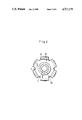
- FIG. 2 is an the pipe union of FIG. 1 in an end view
- FIG. 3 is a section view of a shaped seal corresponding to FIG. 1a;
- FIG. 4 is an end view of the shaped seal of FIG. 3;
- FIG. 5 is a section view of a clamping disk corresponding to FIG. 3;
- FIG. 6 is a plan view of the clamping disk of FIG. 5;
- FIG. 7 is a section view of an inner ring of the shaped seal corresponding to FIG. 1a;
- FIG. 8 is a plan view of the inner ring of FIG. 7;
- FIG. 9 is a section view of a cap disk corresponding to FIG. 1a;
- FIG. 10 is a plan view of the cap disk of FIG. 9;
- FIG. 11 shows a flange in a section corresponding to FIG. 1a
- FIG. 12 is a plan view of the flange of FIG. 11;
- FIG. 13 is a plan view of a shell in plan view.
- FIG. 14 is various detail sections taken through the shell of FIG. 13.
- the shaped seal of the invention has two axial ends each protruding into a respective adapted recess of a pair of seal chamber elements covering the seal.
- the seal comprises an outer elastomer ring supported on the jacket faces of the two pipe ends and has a central annular groove that is open to the inside. An inner ring that overlaps the end-to-end butt joint is pressed loosely into this central annular groove.
- the clamping elements are supported with a radially inwardly located clamping rim on the associated pipe end, and with a radially outwardly located clamping rim on a clamping face disposed concentrically to the pipe ends.
- the clamping elements are curved outward in the axial direction in such a manner that an axial force exerted upon the clamping element in the direction toward the butt joint causes an increase in the outside diameter and a decrease in the inside diameter of the clamping element.
- the invention provides for embodying the clamping element and the chamber element each as clamping disks, which can advantageously be firmly joined to the shaped seal.
- the shaped seal can be fabricated in an injection molding die, into which the two outwardly located clamping disks as well as the above-mentioned inner ring are placed.
- the inner ring is not firmly joined to the elastomer by the injection molding process, however.
- the clamping disks preferably have radial slits, which during the injection molding process become filled up with the elastomer, thereby producing a form-fitting union between the two clamping disks and the shaped seal.
- the two clamping disks, the elastomer ring and the inner ring of the elastomer ring all form a single structural part, which is easy to handle and can be rapidly assembled.
- the radially outwardly located clamping rim of the clamping disk can include an outer leg that is bent away from the butt joint and which is adjoined by an inner leg that is bent in the opposite direction.
- the clamping disk can be resilient. It is also possible, however, for the annular bend between the outer leg and the inner leg to be embodied as a predetermined breaking point. In a modified embodiment, the clamping disk can also comprise a separate outer ring and a separate inner ring.
- a cap disk can be pushed loosely onto each of the pipe ends between the flange and the clamping disk.
- the cap disk can be embodied similarly to the clamping disk and may additionally exert a clamping action as well.
- the cap disk preferably has radial notches, but the number of notches should be different from the number of radial slits in the clamping disk. This is intended to prevent the elastomer from passing through the radial slits and getting into the notches of the cap disks.
- Each cap disk should have at least six notches.
- the cap disk may be supported with a bent outer leg against a conical annular surface of the associated flange.
- a pipe segment the inner jacket of which forms the clamping faces for the clamping disks as well as a support surface for the shaped seal, can be fitted onto the two flanges.
- the inner ring of the shaped seal can plunge with a respective cone into the associated pipe end, with the greatest conical diameter being somewhat greater than the inside diameter of the inside of the pipe.
- Conceivable examples include screw connections, bayonet closures, and the like.
- a purely plug connection appears to be particularly suitable, comprising respective shells each overlapping one flange, which are joined together in the braced state by means of a plug connection.
- the novel pipe union is particularly suitable for high pressures and for absorbing pressure pulsations and vibrations.
- the pipe union can be used particularly to join pipes of relatively small diameter, for instance in joining brake and fuel pipes in the automotive industry.
- the fields where these pipe unions are applicable also encompass more than the automotive industry; in particular, they also include the general fields of hydraulics and pneumatics.
- An important advantage of the pipe union is its amenability to assembly by robots, because the union is effected without threads, screws, or the like.
- the novel pipe union is also suitable for use in domestic engineering, however.
- hard-soldered copper pipes are conveniently used, even though specialists in the field have long been aware that every hard-soldered point is a point where corrosion can occur.
- soldered points offers substantial advantages.
- by means of the novel pipe union it becomes possible for the first time to use special-steel pipes in domestic engineering.
- the pipe union according to FIG. 1 comprises two pipe ends 1,2 that are to be in joined end-to-end relation to one another, and onto each of which a respective shell 3 or 4, a flange 5, and a cap disk 6 are first fitted.
- a shaped seal is provided, which comprises an outer elastomer ring 7, supported on the jacket faces of the two pipe ends 1,2 and having a central annular groove 7a open toward the inside.
- An inner ring 9 that overlaps the end-to-end (butt) joint 8 between the two pipe ends 1,2 is pressed loosely into the annular groove 7a.
- a pipe segment 10 is fitted onto the two flanges 5. To effect the pipe union, the two flanges 5 are pressed against one another in the axial direction far enough that the two sheels 3,4 that overlap one another lock into place with one another and thus effect a form-fitting union.
- FIG. 3 shows that the elastomer ring 7 is covered on both sides by clamping disk 11, which are shown in greater detail in FIGS. 5 and 6.
- each clamping disk 11 has five relatively wide radial slits 12, into which the elastomer comprising the ring 7 penetrates when the shaped seal is injection molded, so that the clamping disks 11 are firmly joined to the elastomer ring 7.
- FIG. 1 shows that the clamping disks 11 are supported with a radially inwardly located clamping rim 11a on the associated pipe end 1 or 2, and with a radially outwardly located clamping rim 11b on the inner wall of the pipe segment 10, the inner wall forming a clamping surface.
- FIG. 5 shows that the radially outwardly located clamping rim 11b is intregral with an outer leg 11c that is bent away from the end-to-end (butt) joint 8 and which is adjoined by an inner leg 11d that is bent in the opposite direction and is preferably longer in length.
- the positioning angle ⁇ of the outer leg 11c defined as the angle formed by the outer leg 11c with a plane 11e parallel to a right angle cross-section of the respective pipe end is larger than the positioning angle ⁇ of the inner leg 11d defined as the angle formed by the inner leg 11b with the plane 11e; preferably, ⁇ equals about 65° and ⁇ equals about 15°.
- the radial slits 12 extend from the inside as far as the radially outwardly located end of the inner leg 11d. These radial slits 12 are present in an odd number and in the exemplary embodiment the number equals five.
- FIGS. 1, 7, and 8 show that the inner ring 9 of the shaped seal is pressed into the undercut annular groove 7a of the elastomer ring and plunges with a respective cone 9a into the associated pipe end 1 or 2.
- the largest cone diameter is somewhat larger than the inside diameter of the inside of the pipe.
- the cap disk 6 which, as shown in FIG. 1, is loosely pressed onto the pipe ends 1,2 between the flange 5 and the clamping disk 11, is adapted to the outwardly curved contour of the clamping disk 11, as FIG. 1 particularly illustrates, and rests on the clamping disk over a large surface area.
- the cap disk 6 also has radial notches 13 (see FIG. 10), which extend from the inside as far as the radially outwardly located end of its inner leg 6a.
- the number of notches 13 should not be equal to the number of radial slits 12 in the clamping disk 11, and in the exemplary embodiment the number of radial notches 13 is six.
- the notches 13 are embodied narrower than the radial slits 12 of the clamping disk 11.
- the cap disk 6 is supported with its bent outer leg 6b against a conical annular face 5a of the associated flange 5 (see FIG. 1 as well as FIGS. 11 and 12).
- the device for bracing the two flanges 5 against one another comprises the two protruding shells 3,4 already mentioned, which are each pushed onto a respective annular collar 5b of the associated flange 5 and have axially extending claws 3a,4a (see FIG. 1 as well as FIGS. 13 and 14).
- the claws of one shell overlap the claws of the outer shell, and the outwardly located claws in each case have a recess 14, which is engaged by a spring tongue 15 that has been stamped out of the claw located therebelow.
- the claws located on the outside in each case have a bent portion 3b,4b on their free end, with which these claws, in a first detent position (see the upper half of FIG. 1), grip the free end of the associated spring tongue from behind and, in a second detent position (see the lower half of FIG. 1), grip the opposing shell, in each case in a form-fitting manner.
- the pipe union is produced merely by pressing the two shells 3,4 axially against one another, until the second detent position as shown in the lower half of FIG. 1 is attained.
- the pipe union is produced merely by pressing the two shells 3,4 axially against one another, until the second detent position as shown in the lower half of FIG. 1 is attained.
Applications Claiming Priority (2)
| Application Number | Priority Date | Filing Date | Title |
|---|---|---|---|
| DE3508296 | 1985-03-08 | ||
| DE19853508296 DE3508296A1 (de) | 1985-03-08 | 1985-03-08 | Rohrverbindung |
Publications (1)
| Publication Number | Publication Date |
|---|---|
| US4717179A true US4717179A (en) | 1988-01-05 |
Family
ID=6264626
Family Applications (1)
| Application Number | Title | Priority Date | Filing Date |
|---|---|---|---|
| US06/837,825 Expired - Fee Related US4717179A (en) | 1985-03-08 | 1986-03-10 | Pipe union for end to end pipes with deformable clamping disks surrounding a seal |
Country Status (5)
| Country | Link |
|---|---|
| US (1) | US4717179A (de) |
| JP (1) | JPS61274195A (de) |
| CH (1) | CH669443A5 (de) |
| DE (1) | DE3508296A1 (de) |
| SU (1) | SU1607695A3 (de) |
Cited By (15)
| Publication number | Priority date | Publication date | Assignee | Title |
|---|---|---|---|---|
| US5249829A (en) * | 1992-07-06 | 1993-10-05 | Quikcoup, Inc. | Pipe coupling gasket insert |
| US5310223A (en) * | 1992-01-16 | 1994-05-10 | Straub Federnfabrik Ag | Pipe coupling |
| US5466019A (en) * | 1994-09-26 | 1995-11-14 | Komolrochanaporn; Naris | Pipe coupling |
| US5527073A (en) * | 1991-07-23 | 1996-06-18 | The University Of Manchester Institute Of Science And Technology | Coupling |
| US6142536A (en) * | 1997-05-06 | 2000-11-07 | Alia Engineering Ag | Pipe coupling |
| US6464266B1 (en) | 1998-12-18 | 2002-10-15 | Accor Technology, Inc. | Tube coupling |
| US6517124B1 (en) | 1999-09-27 | 2003-02-11 | Legris S.A. | Device for connecting a pipe end to a member |
| US20040239117A1 (en) * | 2003-05-28 | 2004-12-02 | Gill Ajit Singh | Coupling for pipe including an inclined flange |
| US20080029966A1 (en) * | 2005-06-14 | 2008-02-07 | More Dominick G | Seal assembly |
| US20080185838A1 (en) * | 2005-03-22 | 2008-08-07 | Straub Werke Ag | Anchoring Element For Pipe Couplings |
| US20090152864A1 (en) * | 2007-12-14 | 2009-06-18 | Uponor Innovation Ab | Method of forming a clamping ring and a clamping ring |
| US20140033507A1 (en) * | 2011-03-03 | 2014-02-06 | Gsa Industries (Aust.) Pty. Ltd. | Pipe coupling |
| CN104455431A (zh) * | 2014-12-23 | 2015-03-25 | 常熟市东方特种金属材料厂 | 一种合金密封圈 |
| US10865923B2 (en) | 2018-11-19 | 2020-12-15 | Accor Technology, Inc. | Push-fit fitting and end bushing for use therewith |
| US10920892B2 (en) | 2018-09-18 | 2021-02-16 | Accor Technology, Inc. | Adapter for connecting tubing with push-fit fittings |
Families Citing this family (5)
| Publication number | Priority date | Publication date | Assignee | Title |
|---|---|---|---|---|
| DE3508296A1 (de) * | 1985-03-08 | 1986-10-09 | Agintec AG, Pfäffikon | Rohrverbindung |
| ES2039550T3 (es) * | 1988-10-18 | 1993-10-01 | Uwe Vieregge | Conexion de tubos y su utilizacion en instalaciones de rociadores. |
| WO1992002753A1 (de) * | 1990-08-02 | 1992-02-20 | Uwe Vieregge | Verbindungselemente von geradlinig sich fortsetzender gas- oder flüssigkeitsführender rohrteile b1/b2 |
| US5725257A (en) * | 1995-05-17 | 1998-03-10 | Honda Giken Kogyo Kabushiki Kaisha | Pipe joint |
| JP6637647B2 (ja) * | 2014-06-06 | 2020-01-29 | 株式会社ブリヂストン | 管継手 |
Citations (26)
| Publication number | Priority date | Publication date | Assignee | Title |
|---|---|---|---|---|
| US1516397A (en) * | 1920-01-27 | 1924-11-18 | Adolph Mueller | Compression coupling |
| US2444380A (en) * | 1940-05-14 | 1948-06-29 | Allen Herbert | Pipe joint connection |
| US2466294A (en) * | 1947-03-24 | 1949-04-05 | Cameron Iron Works Inc | Seal assembly |
| US2653042A (en) * | 1950-01-30 | 1953-09-22 | Northrop Aircraft Inc | Demountable duct seal |
| US2670223A (en) * | 1950-08-25 | 1954-02-23 | Fred H Ream | Pipe coupling |
| US2852282A (en) * | 1951-07-16 | 1958-09-16 | Aeroquip Corp | Flexible fluid sealed joint for rigid tubes |
| US3058762A (en) * | 1958-11-17 | 1962-10-16 | Earl E Howe | Screw thimble fitting having toggle rings with a sealing feature |
| US3116078A (en) * | 1961-07-18 | 1963-12-31 | Bernard F Scherer | Coupling having annularly arranged u-shaped gripping members retained against movement in sleeve |
| US3189371A (en) * | 1961-12-22 | 1965-06-15 | Shell Oil Co | Joint for lined pipe sections with gasket compression limiting means |
| US3204988A (en) * | 1960-05-18 | 1965-09-07 | Dresser Ind | Stab type pipe coupling with gasket back up ring |
| US3365217A (en) * | 1966-04-04 | 1968-01-23 | Foster Wheeler Corp | Expansion joint |
| US3454287A (en) * | 1967-06-21 | 1969-07-08 | Certain Teed Prod Corp | Insulated coupling for grooved end pipe |
| DE1925171A1 (de) * | 1968-05-21 | 1969-11-27 | Park & Co Forgemasters Ltd Wm | Verbindungsvorrichtung oder Kupplung |
| GB1178248A (en) * | 1966-09-29 | 1970-01-21 | Robert Archibald Gordo Lindsay | An Improved Pipe Coupling. |
| US3498649A (en) * | 1967-08-16 | 1970-03-03 | Anton Pfeuffer | Pipe clamping and centering device |
| US3580617A (en) * | 1968-05-28 | 1971-05-25 | Fouquet Werk Frauz & Planck | Pipe union |
| US3679241A (en) * | 1969-06-11 | 1972-07-25 | Schmidt & Co Gmbh Kranz | Compression pipe coupling |
| DE2309783A1 (de) * | 1972-03-01 | 1973-09-13 | Skil Nederland Nv | Geschwindigkeitssteuerungseinrichtung fuer ein tragbares elektrisches werkzeug |
| US3776579A (en) * | 1971-03-11 | 1973-12-04 | Stanley Aviation Corp | Coupling assemblies |
| US3837687A (en) * | 1972-12-29 | 1974-09-24 | G Leonard | Coupling for tubing |
| US4181329A (en) * | 1979-02-02 | 1980-01-01 | Gordon H. Cork | Releasable tube coupling |
| US4372586A (en) * | 1980-09-25 | 1983-02-08 | Peretz Rosenberg | Rod clamp particularly useful as pipe coupling |
| DE3206570A1 (de) * | 1982-02-24 | 1983-09-01 | Hans Paul 7730 Villingen-Schwenningen Maier | Rohrverbindung |
| US4418948A (en) * | 1981-05-06 | 1983-12-06 | Lew Hyok S | Elastic coupling for pipes and tubes |
| US4480861A (en) * | 1981-02-18 | 1984-11-06 | Columbus Standard, Inc. | Pipe joint and apparatus therefor |
| DE3508296A1 (de) * | 1985-03-08 | 1986-10-09 | Agintec AG, Pfäffikon | Rohrverbindung |
-
1985
- 1985-03-08 DE DE19853508296 patent/DE3508296A1/de active Granted
-
1986
- 1986-03-03 CH CH853/86A patent/CH669443A5/de not_active IP Right Cessation
- 1986-03-07 JP JP61050285A patent/JPS61274195A/ja active Pending
- 1986-03-07 SU SU864027105A patent/SU1607695A3/ru active
- 1986-03-10 US US06/837,825 patent/US4717179A/en not_active Expired - Fee Related
Patent Citations (27)
| Publication number | Priority date | Publication date | Assignee | Title |
|---|---|---|---|---|
| US1516397A (en) * | 1920-01-27 | 1924-11-18 | Adolph Mueller | Compression coupling |
| US2444380A (en) * | 1940-05-14 | 1948-06-29 | Allen Herbert | Pipe joint connection |
| US2466294A (en) * | 1947-03-24 | 1949-04-05 | Cameron Iron Works Inc | Seal assembly |
| US2653042A (en) * | 1950-01-30 | 1953-09-22 | Northrop Aircraft Inc | Demountable duct seal |
| US2670223A (en) * | 1950-08-25 | 1954-02-23 | Fred H Ream | Pipe coupling |
| US2852282A (en) * | 1951-07-16 | 1958-09-16 | Aeroquip Corp | Flexible fluid sealed joint for rigid tubes |
| US3058762A (en) * | 1958-11-17 | 1962-10-16 | Earl E Howe | Screw thimble fitting having toggle rings with a sealing feature |
| US3204988A (en) * | 1960-05-18 | 1965-09-07 | Dresser Ind | Stab type pipe coupling with gasket back up ring |
| US3116078A (en) * | 1961-07-18 | 1963-12-31 | Bernard F Scherer | Coupling having annularly arranged u-shaped gripping members retained against movement in sleeve |
| US3189371A (en) * | 1961-12-22 | 1965-06-15 | Shell Oil Co | Joint for lined pipe sections with gasket compression limiting means |
| US3365217A (en) * | 1966-04-04 | 1968-01-23 | Foster Wheeler Corp | Expansion joint |
| GB1178248A (en) * | 1966-09-29 | 1970-01-21 | Robert Archibald Gordo Lindsay | An Improved Pipe Coupling. |
| US3454287A (en) * | 1967-06-21 | 1969-07-08 | Certain Teed Prod Corp | Insulated coupling for grooved end pipe |
| US3498649A (en) * | 1967-08-16 | 1970-03-03 | Anton Pfeuffer | Pipe clamping and centering device |
| DE1925171A1 (de) * | 1968-05-21 | 1969-11-27 | Park & Co Forgemasters Ltd Wm | Verbindungsvorrichtung oder Kupplung |
| US3580617A (en) * | 1968-05-28 | 1971-05-25 | Fouquet Werk Frauz & Planck | Pipe union |
| US3679241A (en) * | 1969-06-11 | 1972-07-25 | Schmidt & Co Gmbh Kranz | Compression pipe coupling |
| US3776579A (en) * | 1971-03-11 | 1973-12-04 | Stanley Aviation Corp | Coupling assemblies |
| DE2309783A1 (de) * | 1972-03-01 | 1973-09-13 | Skil Nederland Nv | Geschwindigkeitssteuerungseinrichtung fuer ein tragbares elektrisches werkzeug |
| US3837687A (en) * | 1972-12-29 | 1974-09-24 | G Leonard | Coupling for tubing |
| US4181329A (en) * | 1979-02-02 | 1980-01-01 | Gordon H. Cork | Releasable tube coupling |
| US4372586A (en) * | 1980-09-25 | 1983-02-08 | Peretz Rosenberg | Rod clamp particularly useful as pipe coupling |
| US4480861A (en) * | 1981-02-18 | 1984-11-06 | Columbus Standard, Inc. | Pipe joint and apparatus therefor |
| US4418948A (en) * | 1981-05-06 | 1983-12-06 | Lew Hyok S | Elastic coupling for pipes and tubes |
| DE3206570A1 (de) * | 1982-02-24 | 1983-09-01 | Hans Paul 7730 Villingen-Schwenningen Maier | Rohrverbindung |
| EP0087702A1 (de) * | 1982-02-24 | 1983-09-07 | Agintec AG | Rohrverbindung |
| DE3508296A1 (de) * | 1985-03-08 | 1986-10-09 | Agintec AG, Pfäffikon | Rohrverbindung |
Cited By (32)
| Publication number | Priority date | Publication date | Assignee | Title |
|---|---|---|---|---|
| US5527073A (en) * | 1991-07-23 | 1996-06-18 | The University Of Manchester Institute Of Science And Technology | Coupling |
| US5310223A (en) * | 1992-01-16 | 1994-05-10 | Straub Federnfabrik Ag | Pipe coupling |
| US5249829A (en) * | 1992-07-06 | 1993-10-05 | Quikcoup, Inc. | Pipe coupling gasket insert |
| US5466019A (en) * | 1994-09-26 | 1995-11-14 | Komolrochanaporn; Naris | Pipe coupling |
| US6142536A (en) * | 1997-05-06 | 2000-11-07 | Alia Engineering Ag | Pipe coupling |
| US6464266B1 (en) | 1998-12-18 | 2002-10-15 | Accor Technology, Inc. | Tube coupling |
| US20030111840A1 (en) * | 1998-12-18 | 2003-06-19 | Accor Technology, Inc. | Tube coupling |
| US7523966B2 (en) | 1998-12-18 | 2009-04-28 | Accor Technology, Inc. | Tube coupling |
| US6860523B2 (en) | 1998-12-18 | 2005-03-01 | Accor Technology, Inc. | Tube coupling |
| US8820799B2 (en) | 1998-12-18 | 2014-09-02 | Accor Technology, Inc. | Tube coupling |
| US7232159B2 (en) | 1998-12-18 | 2007-06-19 | Accor Technology, Inc. | Tube coupling |
| US20070241562A1 (en) * | 1998-12-18 | 2007-10-18 | Accor Technology, Inc. | Tube coupling |
| US7810850B2 (en) | 1998-12-18 | 2010-10-12 | Accor Technology, Inc. | Tube coupling |
| US20080143106A1 (en) * | 1998-12-18 | 2008-06-19 | Accor Technology, Inc. | Tube coupling |
| US20090243288A1 (en) * | 1998-12-18 | 2009-10-01 | Accor Technology, Inc. | Tube coupling |
| US6517124B1 (en) | 1999-09-27 | 2003-02-11 | Legris S.A. | Device for connecting a pipe end to a member |
| US20040239117A1 (en) * | 2003-05-28 | 2004-12-02 | Gill Ajit Singh | Coupling for pipe including an inclined flange |
| US6921115B2 (en) | 2003-05-28 | 2005-07-26 | Ajit Singh Gill | Coupling for pipe including an inclined flange |
| US20080185838A1 (en) * | 2005-03-22 | 2008-08-07 | Straub Werke Ag | Anchoring Element For Pipe Couplings |
| US20100032942A1 (en) * | 2005-03-22 | 2010-02-11 | Straub Werke Ag | Anchoring element for pipe couplings |
| US7866707B2 (en) | 2005-03-22 | 2011-01-11 | Straub Werke Ag | Anchoring element for pipe couplings |
| US20080029966A1 (en) * | 2005-06-14 | 2008-02-07 | More Dominick G | Seal assembly |
| US8764021B2 (en) * | 2005-06-14 | 2014-07-01 | Parker-Hannifin Corporation | Seal assembly |
| US10093063B2 (en) | 2007-12-14 | 2018-10-09 | Uponor, Inc. | Clamping ring |
| US8146225B2 (en) * | 2007-12-14 | 2012-04-03 | Uponor Innovation Ab | Method of forming a clamping ring and a clamping ring |
| US20090152864A1 (en) * | 2007-12-14 | 2009-06-18 | Uponor Innovation Ab | Method of forming a clamping ring and a clamping ring |
| US20140033507A1 (en) * | 2011-03-03 | 2014-02-06 | Gsa Industries (Aust.) Pty. Ltd. | Pipe coupling |
| US9228681B2 (en) * | 2011-03-03 | 2016-01-05 | Reliance Worldwide Corporation (Aust.) Pty. Ltd. | Pipe coupling |
| CN104455431A (zh) * | 2014-12-23 | 2015-03-25 | 常熟市东方特种金属材料厂 | 一种合金密封圈 |
| US10920892B2 (en) | 2018-09-18 | 2021-02-16 | Accor Technology, Inc. | Adapter for connecting tubing with push-fit fittings |
| US11313474B2 (en) | 2018-09-18 | 2022-04-26 | Accor Technologies, Inc. | Adapter for connecting tubing with push-fit fittings |
| US10865923B2 (en) | 2018-11-19 | 2020-12-15 | Accor Technology, Inc. | Push-fit fitting and end bushing for use therewith |
Also Published As
| Publication number | Publication date |
|---|---|
| JPS61274195A (ja) | 1986-12-04 |
| DE3508296C2 (de) | 1987-01-29 |
| SU1607695A3 (ru) | 1990-11-15 |
| CH669443A5 (de) | 1989-03-15 |
| DE3508296A1 (de) | 1986-10-09 |
Similar Documents
| Publication | Publication Date | Title |
|---|---|---|
| US4717179A (en) | Pipe union for end to end pipes with deformable clamping disks surrounding a seal | |
| US3054629A (en) | Pipe couplings | |
| US4437691A (en) | Connector for corrugated tubing | |
| RU1802859C (ru) | Трубное соединение | |
| US3972547A (en) | Locking and nonseal joint device | |
| US4119335A (en) | Pipe and tubing connectors | |
| US6896299B1 (en) | Resin pipe joint | |
| SU727162A1 (ru) | МУФТА ДЛЯ СОЕДИНЕНИЯ ТРУБ (51) М. Кл? (53) УДК 6 2-7 6 2 (088.8) 1 | |
| KR100307809B1 (ko) | 수지제관이음매 | |
| US4807912A (en) | Pipe coupling | |
| KR930001669B1 (ko) | 캔틸레버 립 도관 커플링 부재 및 조립체 | |
| US4568114A (en) | Threaded pipe connector | |
| US4143884A (en) | Sealing member for spigot-and-socket pipe coupling | |
| US7665772B2 (en) | Metallic cutting ring | |
| US4371179A (en) | T-Shaped sealing ring with elongated lip | |
| US4240655A (en) | Pipe coupling | |
| EP1031493A1 (de) | Steuerungssystem für fahrzeuge | |
| US3363912A (en) | Seal gasket | |
| US3408096A (en) | Pipe coupling | |
| KR200157563Y1 (ko) | 배관이음용 커플링 | |
| KR200373716Y1 (ko) | 합성수지이중벽관의 클립형 연결장치 | |
| GB2100819A (en) | Pipe joint for plastics pipes | |
| RU2042075C1 (ru) | Раструбное соединение труб | |
| KR200142598Y1 (ko) | 관연결구용 원통형 보조패킹 | |
| KR200321875Y1 (ko) | 압입 결합식 관이음장치 |
Legal Events
| Date | Code | Title | Description |
|---|---|---|---|
| AS | Assignment |
Owner name: AGINTEC AG, SCHINDELLEGISTRASSE 75, CH-8808 PFAEFF Free format text: ASSIGNMENT OF ASSIGNORS INTEREST.;ASSIGNORS:HABERSTOCK, ROLF;TRISSLER, HEINRICH;VLAYKOWSKI, NIKOLAV;AND OTHERS;REEL/FRAME:004535/0259;SIGNING DATES FROM 19860307 TO 19860308 |
|
| REMI | Maintenance fee reminder mailed | ||
| LAPS | Lapse for failure to pay maintenance fees | ||
| FP | Expired due to failure to pay maintenance fee |
Effective date: 19911229 |
|
| STCH | Information on status: patent discontinuation |
Free format text: PATENT EXPIRED DUE TO NONPAYMENT OF MAINTENANCE FEES UNDER 37 CFR 1.362 |