US4667751A - System and method for controlled directional drilling - Google Patents
System and method for controlled directional drilling Download PDFInfo
- Publication number
- US4667751A US4667751A US06/786,817 US78681785A US4667751A US 4667751 A US4667751 A US 4667751A US 78681785 A US78681785 A US 78681785A US 4667751 A US4667751 A US 4667751A
- Authority
- US
- United States
- Prior art keywords
- borehole
- drillstring
- concentric
- stabilizer
- feet
- Prior art date
- Legal status (The legal status is an assumption and is not a legal conclusion. Google has not performed a legal analysis and makes no representation as to the accuracy of the status listed.)
- Ceased
Links
Images


Classifications
-
- E—FIXED CONSTRUCTIONS
- E21—EARTH OR ROCK DRILLING; MINING
- E21B—EARTH OR ROCK DRILLING; OBTAINING OIL, GAS, WATER, SOLUBLE OR MELTABLE MATERIALS OR A SLURRY OF MINERALS FROM WELLS
- E21B7/00—Special methods or apparatus for drilling
- E21B7/04—Directional drilling
- E21B7/06—Deflecting the direction of boreholes
- E21B7/068—Deflecting the direction of boreholes drilled by a down-hole drilling motor
-
- E—FIXED CONSTRUCTIONS
- E21—EARTH OR ROCK DRILLING; MINING
- E21B—EARTH OR ROCK DRILLING; OBTAINING OIL, GAS, WATER, SOLUBLE OR MELTABLE MATERIALS OR A SLURRY OF MINERALS FROM WELLS
- E21B7/00—Special methods or apparatus for drilling
- E21B7/04—Directional drilling
- E21B7/06—Deflecting the direction of boreholes
- E21B7/067—Deflecting the direction of boreholes with means for locking sections of a pipe or of a guide for a shaft in angular relation, e.g. adjustable bent sub
Definitions
- the present invention relates generally to improvements in controlled directional drilling systems and more particularly pertains to a new and improved system and method for controlling the directional drilling of the borehole in a manner which will allow the borehole to be drilled in conformance with the proposed well plan.
- Deviating boreholes have been a subject of concern to this industry for a long time. Many approaches have been tried to first understand the multifacet problem and then to come up with a workable solution. One example of such an approach can be found in SPE Article No. 5070 entitled “Factors Affecting the Control of Borehole Angle In Straight and Directional Wells" presented at the SPE-AIME 49th Annual Fall Meeting in Houston, Tex., Oct. 6-9, 1974.
- the present invention is an improvement over the systems presently available and being tried by the industry to increase ROP of a directional well.
- the improved performance of the present invention is based on the fact that an overall system approach to each drilling job is utilized.
- the bottom-hole assembly is uniquely tailored for each proposed well plan by taking into consideration a myriad of facts such as hole condition, pump data, type of mud being utilized, type of formation being drilled, drilling assembly components, drilling flow rate, well plan, i.e. direction of the borehole after deviating from vertical, in addition to information about the drilling bit which includes bit size, bit type, bit pressure drop, and gauge length, as well as degrees of offset of the center line of the bit face from the center line of the borehole.
- This information is utilized according to the present invention to come up with a bottom hole assembly and method of building a bottom hole assembly which provides an ROP for directional wells which is considerably higher than was heretofore possible.
- a system approach to the design of a down-hole assembly for directional drilling requires establishing the value for a series of important variables on the basis of the proposed well plan.
- the major variables which are systematically determined are bit offset from center, determined by the angle of bend in a bent housing located between the motor and the bit, exact placement along the drillstring of a plurality of concentric stabilizers with respect to the bit, diametric size of each concentric stabilizer with respect to the diameter of the borehole, and to a lesser degree weight on the bit.
- the entire system, when assembled for a particular well plan is capable of following that well plan with only slight directional correction in the borehole.
- Directional corrections are made and control of the system is maintained by rotating the down-hole motor only, for curved travel of the drillstring, and rotating the motor and drill string together for straight travel of the drillstring.
- FIG. 1 is a diagramatic illustration of the basic components of the bottom-hole assembly of the present invention
- FIG. 2 is a diagramatic illustration showing how the bit offset is obtained in the bottom-hole assembly according to the invention
- FIG. 3 is a vector illustration showing how the bottom hole assembly, of the present invention drills in a controlled direction
- FIG. 4 is a table and component diagram for a bottom-hole assembly built according to the present invention illustrating the interrelationship of the basic components of the bottom-hole assembly;
- FIG. 5 is an alternate table and diagram illustrating a different relationship between the basic components of the bottom-hole assembly of the present invention.
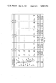
- FIG. 6 is a vertical section of a borehole showing the accuracy with which the actual borehole follows the proposed well plan.
- the borehole 13 is shown in an oversized and exaggerated manner and is illustrated as being capable of moving in three dimensional space as defined by the Cartesian coordinates x, y and z.
- the z axis is for the purposes of illustration, defined as the center line of the borehole 13.
- the first element of the bottom-hole assembly of the present invention is the drill bit 15 which is connected to a shaft that is concentrically located within a bearing assembly 17. This shaft is in turn connected through a bent housing 21 to the output shaft of the down-hole motor 25.
- the housing of the down-hole motor 25 is in turn connected to the drill string casing 27 which extends all the way to the surface of the borehole 13 and is in turn connected to a means for rotating the entire assembly from the surface (not shown).
- the bottom-hole assembly also includes at least three and preferably four stabilizers 19, 29, 31 and 33 precisely located along the drill string with respect to the drill bit 15 and with respect to each other.
- FIG. 2 illustrates the turning mechanism of the bottom-hole assembly built according to the present invention.
- This turning mechanism includes the bent housing 21, 23 having a specific tilt angle 35 and a concentric stabilizer 19 located down-hole of the tilt point 23 on the bent housing 21, 23, and very close to bit 15 on bearing housing 17.
- the drive shaft for bit 15 is concentric within bearing housing 17, resulting in an offset 35 of the center of the face of the bit 15 from the centerline of the borehole 13 by an angle ⁇ which is the tilt angle 35 of the bent housing 21.
- the down-hole motor 25 utilized with this type of arrangement is preferably a positive displacement motor of the type described in the SPE paper No. 13026 entitled "PDM Versus Turbo-Drill: A drilling comparison”.
- the concentric stabilizer 19 located close to the bit 15 serves mainly to maintain the bit offset angle 35 by minimizing the deflections which might increase or decrease this offset angle.
- a curve which is made up of a plurality of segments 37, 45, 49, 53 and 57 is illustrated as the curve along which the bottom-hole assembly of the present invention will travel as determined by the elements of the bottom-hole assembly including bearing stabilizer 19 and the other stabilizers making up the bottom-hole assembly.
- the bottom most three stabilizers can be thought of as defining points on a circle which determine the radius of the circle. A portion of the circumference of this circle is illustrated in FIG. 3 as the path of travel of the bottom-hole assembly.
- the vertical distance 59 for the curved path traveled is for convenience considered to be a segment of 100 feet.
- the initial deviation from vertical 39 of curved segment 37 is determined by the bit offset 41 which is controlled by a tilt angle of bent housing 21, 23.
- the bit 15 will travel along this offset path 37 for a length 61 which is approximately equal to the length of the bearing assembly 17. Whereupon the bit will again follow its offset 41 to drill the next straight segment 45 rather than continue straight along segment 43, and so on to segments 53 and 57.
- the composite result is a curved path which deviates from the original vertical 39 by a total angle in degrees which is related to the angle of offset 41 created by the tilt angle in bent housing 21, 23.
- the bearing stabilizer 19 and the bent housing 21, 23 is considered the part of the overall system which gives the bottom-hole assembly the capability of turning left or right in a controlled manner.
- the three concentric stabilizers 19, 29 and 31 and, preferably the fourth concentric stabilizer 33 can be considered as the part of the bottom-hole assembly which gives the assembly the ability to maintain a straight course, or to build or drop angle.
- the bottom-hole assembly of the present invention is really a unique combination of two overlapping systems which are integrated to provide the bottom-hole assembly with its unique performance capabilities.
- FIG. 4 illustrates one such set of relationships.
- the basic down-hole assembly components are the drill bit 63, the concentric stabilizers 65, 69, 71 and 73, and the bent housing 67, having an offset angle ⁇ . Performance of this bottom-hole assembly, is changed by varying the distance of each stabilizer from the bit 63. That is the distance L1 of stabilizer 65 from bit 63, the distance L1+L2 of the stabilizer 69 from the bit 63, the distance L1+L2+L3 of the stabilizer 71 and the distance L1+L2+L3+L4 of the stabilizer 73 from the bit 63.
- the angle ⁇ is an important contributing factor, as well as the amount of undersize ⁇ d 75 of each stabilizer with respect to the hole size.
- the amount of weight on bit (WOB) is a factor, as are various other variables mentioned above, to a minor extent.
- bottom-hole assemblies which for convenience are designated as assemblies A, B and C.
- assembly A the hole size is given as 121/4 inches.
- Hole washout, as a result of the bottom-hole assembly will be negligable.
- This bottom-hole assembly utilizes a bent housing which has a bit offset angle ⁇ of 1/4 of a degree.
- the placement of the four stabilizers is as follows.
- the bearing stabilizer 65 is located a distance L1 from the bit which is equal to 41/4 feet.
- Stabilizer 69 is located a distance L2 from the stabilizer 65 which is a distance of 31 feet.
- Stabilizer 71 is located a distance L3 from stabilizer 69 which is a distance of 45 feet.
- Stabilizer 73 is located a distance L4 from stabilizers 71 which is a distance of 35 feet. Each of the stabilizers are concentric and undersized with respect to the hole diameter an amount ⁇ d which is equal to 0.032 inches. The location of the four stabilizers 65, 69, 71 and 73 at these specific distances with respect to the bit 63 has been found to create a system that will build 0.30 degrees per 100 feet regardless of the variation of the weight on bit from 10,000 pounds to 40,000 pounds.
- this combination causes the bottom-hole assembly to build angle at 0.58 degrees per 100 feet.
- the system when being utilized in a directional drilling mode, will build angle at 0.88 degrees per 100 feet. It can be seen that prior to putting this bottom-hole assembly into the ground, its performance in the directional mode can be fairly accurately predicted.
- Bottom-hole assembly B has an offset angle ⁇ of half a degree and utilizes a bearing stabilizer 65 which is undersized by 0.157 inches. All the other parameters remain the same. The four stabilizers thereby provide a bottom-hole assembly which drops angle at 0.59 degrees per 100 feet. The bent housing and bearing stabilizer causes the bottom-hole assembly to build angle by 0.75 degrees per 100 feet. The resulting overall system will therefore build angle by 0.16 degree per 100 feet when in the directional mode.
- the offset angle ⁇ and the undersize differential of the bearing stabilizer 65 is chosen to be 3/4 of a degree and the bearing stabilizer 65 is undersized by 0.282 inches.
- the characteristic of the stabilizer string is to drop angle by 1.48 degree per 100 feet, up to 1.49 degrees per 100 feet, if the weight on bit is increased from 10,000 pounds.
- the bent housing and bearing stabilizers 65 will build angle at 0.92 degrees per 100 feet, up to 0.95 degrees per 100 feet if the weight on bit is increased to 40,000 pounds. Accordingly, the combination results in a directional bottom-hole assembly which will drop angle at 0.56 degrees per 100 feet.
- FIG. 5 illustrates three more bottom-hole assemblies D, E and F.
- the bottom-hole assembly D utilizes an offset angle ⁇ of a quarter of a degree and stabilizer spacing of L1--41/4 feet, L2--31 feet, L3--35 feet, and L4--45 feet, with an undersized diameter differential ⁇ d of 0.032 for each of the concentric stabilizers.
- This system is shown to build angle at 1.01 degrees per 100 feet up to 1.22 degrees per 100 feet as the weight on bit is increased to 40,000 pounds.
- the bent housing and bearing stabilizer 65 will cause the bottom-hole assembly to build angle by 1.27 degrees per 100 feet up 1.50 degrees per 100 feet as the weight-on bit is increased to 40,000 pounds.
- the bottom-hole assembly D will build angle from 2.28 degrees per 100 feet to 2.72 degrees per 100 feet depending upon the amount of weight-on bit.
- the bottom assembly E is shown as utilizing an offset angle ⁇ of 1/2 a degree and a ⁇ d for bearing stabilizer 65 of 0.157 inches. All other variables remain the same.
- the stabilizer section of the bottom-hole assembly will build angle at 0.14 degrees per 100 feet up to 0.33 degrees per 100 feet, depending upon the weight on a bit.
- the bent housing portion of the bottom-hole assembly will tend to build angle at 1.44 degrees per 100 feet up to 1.68 degrees per hundred feet depending on the weight on bit.
- the overall system will tend to drill directionally at 1.58 degrees per 100 feet up to 2.01 degrees per 100 feet depending upon the weight on the bit.
- the bent housing used has an offset angle ⁇ of 3/4 of a degree and a ⁇ d undersized bearing stabilizer 65 at 0.282 inches. All other variables remain the same.
- the stabilizer section will drop angle from 0.72 degrees per 100 feet to 0.56 degrees per 100 feet depending on weight on bit.
- the bent housing will tend to build angle at 1.61 degree per 100 feet to 1.87 degree per 100 feet.
- the combination will drill directionally to build angle of 0.89 degrees per 100 feet up to 1.31 degrees per 100 feet depending upon weight on bit.
- a typical well plan is shown in FIG. 6 where the borehole is drilled vertically for approximately 1,850 feet from the surface 77, at which point it is kicked off and then drilled at a certain angle to a vertical depth of 6,300 feet and an angle depth of 7,970 feet.
- the bottom-hole assembly of the present invention is assembled at the surface with the concentric stabilizers located at distances L1, L2, L3, and L4 and having a differential undersize as specified, and a specific offset angle ⁇ to accomplish the kickoff at 1,850 feet and follow the well plan as shown in FIG. 6.
- both the down-hole motor and the drillstring are rotated together. Rotation of the drillstring nullifies the directional characteristic built-in to the down-hole assembly.
- the down-hole motor is rotated causing the down-hole assembly to take on its full directional characteristic, kick-off and follow the well plan.
- the drillstring can again be rotated if the down-hole assembly starts to build too great an angle. In this way the down-hole assembly is steered to its target.
- the result, as the curves of FIG. 6 illustrate, is that the gyrosurvey data 83 is almost overlaying the proposed well plan 79.
- the actual results of the bottom-hole assembly of the present invention were surprising as is evident from this example.
- the well plan required that the downhole assembly maintain 43 degrees per 56 feet of deviation angle from a depth of 3,077 feet to a depth of 7,216 feet in an 81/2 inch hole.
- the bottom-hole assembly of the present system was used with an offset angle of 1/2 degree.
- the average rate of penetration of the bottom-hole assembly was 103.5 feet per hour.
- the rate of penetration while drilling was 147 feet per hour which reached up to 330 feet per hour.
- the system hit the target 6 feet under average angle and 40 feet to the right. Total cost savings was $112,500 as a result of being 3/4 of a day ahead of schedule.
- the ROP can be increased considerably, resulting in significant savings per well.
Landscapes
- Life Sciences & Earth Sciences (AREA)
- Engineering & Computer Science (AREA)
- Geology (AREA)
- Mining & Mineral Resources (AREA)
- Physics & Mathematics (AREA)
- Environmental & Geological Engineering (AREA)
- Fluid Mechanics (AREA)
- General Life Sciences & Earth Sciences (AREA)
- Geochemistry & Mineralogy (AREA)
- Earth Drilling (AREA)
Priority Applications (9)
| Application Number | Priority Date | Filing Date | Title |
|---|---|---|---|
| US06/786,817 US4667751A (en) | 1985-10-11 | 1985-10-11 | System and method for controlled directional drilling |
| CA000517646A CA1260453A (en) | 1985-10-11 | 1986-09-05 | System and method for controlled directional drilling |
| PCT/US1986/001987 WO1987002408A1 (en) | 1985-10-11 | 1986-09-23 | System and method for controlled directional drilling |
| EP19860906146 EP0243401A4 (de) | 1985-10-11 | 1986-09-23 | System und verfahren zum gezielten bohren. |
| GR862459A GR862459B (en) | 1985-10-11 | 1986-09-29 | System and method for controlled directional drilling |
| ES8602541A ES2002836A6 (es) | 1985-10-11 | 1986-10-10 | Un sistema y su metodo para taladrado direccional controlado |
| BR8604960A BR8604960A (pt) | 1985-10-11 | 1986-10-10 | Sistema e processo para perfuracao direcional controlada de um furo de sondagem |
| NO872419A NO872419L (no) | 1985-10-11 | 1987-06-10 | System og fremgangsmaate for styrt retningsboring. |
| US07/356,270 USRE33751E (en) | 1985-10-11 | 1989-05-23 | System and method for controlled directional drilling |
Applications Claiming Priority (1)
| Application Number | Priority Date | Filing Date | Title |
|---|---|---|---|
| US06/786,817 US4667751A (en) | 1985-10-11 | 1985-10-11 | System and method for controlled directional drilling |
Related Child Applications (1)
| Application Number | Title | Priority Date | Filing Date |
|---|---|---|---|
| US07/356,270 Reissue USRE33751E (en) | 1985-10-11 | 1989-05-23 | System and method for controlled directional drilling |
Publications (1)
| Publication Number | Publication Date |
|---|---|
| US4667751A true US4667751A (en) | 1987-05-26 |
Family
ID=25139668
Family Applications (1)
| Application Number | Title | Priority Date | Filing Date |
|---|---|---|---|
| US06/786,817 Ceased US4667751A (en) | 1985-10-11 | 1985-10-11 | System and method for controlled directional drilling |
Country Status (7)
| Country | Link |
|---|---|
| US (1) | US4667751A (de) |
| EP (1) | EP0243401A4 (de) |
| BR (1) | BR8604960A (de) |
| CA (1) | CA1260453A (de) |
| ES (1) | ES2002836A6 (de) |
| GR (1) | GR862459B (de) |
| WO (1) | WO1987002408A1 (de) |
Cited By (60)
| Publication number | Priority date | Publication date | Assignee | Title |
|---|---|---|---|---|
| US4817740A (en) * | 1987-08-07 | 1989-04-04 | Baker Hughes Incorporated | Apparatus for directional drilling of subterranean wells |
| US4828053A (en) * | 1988-01-12 | 1989-05-09 | Maurer Engineering, Inc. | Deviated wellbore drilling system and apparatus |
| US4848486A (en) * | 1987-06-19 | 1989-07-18 | Bodine Albert G | Method and apparatus for transversely boring the earthen formation surrounding a well to increase the yield thereof |
| US4874045A (en) * | 1988-12-27 | 1989-10-17 | Clayton Charles H | Straight hole drilling method and assembly |
| US4877092A (en) * | 1988-04-15 | 1989-10-31 | Teleco Oilfield Services Inc. | Near bit offset stabilizer |
| US4880066A (en) * | 1987-04-13 | 1989-11-14 | Shell Oil Company | Assembly for directional drilling of boreholes |
| US4932482A (en) * | 1989-07-17 | 1990-06-12 | Smith International, Inc. | Downhole motor with an enlarged connecting rod housing |
| US4938298A (en) * | 1989-02-24 | 1990-07-03 | Becfield Horizontal Drilling Services Company | Directional well control |
| US4962818A (en) * | 1989-07-17 | 1990-10-16 | Smith International, Inc. | Downhole motor with an enlarged connecting rod housing |
| US4991668A (en) * | 1989-02-06 | 1991-02-12 | Maurer Engineering, Inc. | Controlled directional drilling system and method |
| US4995465A (en) * | 1989-11-27 | 1991-02-26 | Conoco Inc. | Rotary drillstring guidance by feedrate oscillation |
| US5033556A (en) * | 1989-02-01 | 1991-07-23 | Baker Hughes Incorporated | Method and apparatus for horizontal drilling |
| US5050692A (en) * | 1987-08-07 | 1991-09-24 | Baker Hughes Incorporated | Method for directional drilling of subterranean wells |
| US5060736A (en) * | 1990-08-20 | 1991-10-29 | Smith International, Inc. | Steerable tool underreaming system |
| US5099931A (en) * | 1988-02-02 | 1992-03-31 | Eastman Christensen Company | Method and apparatus for optional straight hole drilling or directional drilling in earth formations |
| US5113953A (en) * | 1988-11-03 | 1992-05-19 | Noble James B | Directional drilling apparatus and method |
| US5117927A (en) * | 1991-02-01 | 1992-06-02 | Anadrill | Downhole adjustable bent assemblies |
| US5139094A (en) * | 1991-02-01 | 1992-08-18 | Anadrill, Inc. | Directional drilling methods and apparatus |
| US5141060A (en) * | 1989-11-01 | 1992-08-25 | Teleco Oilfield Services Inc. | Method for optimizing of stabilizer positioning in a bottomhole assembly to eliminate the effects of borehole inclination |
| US5148877A (en) * | 1990-05-09 | 1992-09-22 | Macgregor Donald C | Apparatus for lateral drain hole drilling in oil and gas wells |
| US5160925A (en) * | 1991-04-17 | 1992-11-03 | Smith International, Inc. | Short hop communication link for downhole mwd system |
| US5180021A (en) * | 1988-12-21 | 1993-01-19 | Champion Stephen E | Orientable stabilizer |
| WO1994009244A1 (en) * | 1992-10-14 | 1994-04-28 | Target Drilling Services As | Underreamer |
| US5394951A (en) * | 1993-12-13 | 1995-03-07 | Camco International Inc. | Bottom hole drilling assembly |
| US5445230A (en) * | 1993-10-01 | 1995-08-29 | Wattenburg; Willard H. | Downhole drilling subassembly and method for same |
| US5490569A (en) * | 1994-03-22 | 1996-02-13 | The Charles Machine Works, Inc. | Directional boring head with deflection shoe and method of boring |
| US5513714A (en) * | 1992-01-31 | 1996-05-07 | Neyrofor-Weir Limited | Stabilization devices for drill motors |
| US5520256A (en) * | 1994-11-01 | 1996-05-28 | Schlumberger Technology Corporation | Articulated directional drilling motor assembly |
| US5527220A (en) * | 1994-03-23 | 1996-06-18 | Halliburton Company | Articulatable joint with multi-faceted ball and socket |
| US5529428A (en) * | 1992-10-08 | 1996-06-25 | Bischof; Albrecht | Metallic structural element for connecting workpieces consisting of wood, woodworking material or plastic |
| US5535835A (en) * | 1992-05-21 | 1996-07-16 | Baroid Technology, Inc. | Straight/directional drilling device |
| US5542482A (en) * | 1994-11-01 | 1996-08-06 | Schlumberger Technology Corporation | Articulated directional drilling motor assembly |
| US5673765A (en) * | 1993-10-01 | 1997-10-07 | Wattenburg; Willard H. | Downhole drilling subassembly and method for same |
| US5727641A (en) * | 1994-11-01 | 1998-03-17 | Schlumberger Technology Corporation | Articulated directional drilling motor assembly |
| US6047784A (en) * | 1996-02-07 | 2000-04-11 | Schlumberger Technology Corporation | Apparatus and method for directional drilling using coiled tubing |
| US6092610A (en) * | 1998-02-05 | 2000-07-25 | Schlumberger Technology Corporation | Actively controlled rotary steerable system and method for drilling wells |
| US6109371A (en) * | 1997-03-23 | 2000-08-29 | The Charles Machine Works, Inc. | Method and apparatus for steering an earth boring tool |
| US6109372A (en) * | 1999-03-15 | 2000-08-29 | Schlumberger Technology Corporation | Rotary steerable well drilling system utilizing hydraulic servo-loop |
| WO2000055468A1 (en) * | 1999-03-15 | 2000-09-21 | Ian Gray | Directional drilling system for hard rock |
| US6158529A (en) * | 1998-12-11 | 2000-12-12 | Schlumberger Technology Corporation | Rotary steerable well drilling system utilizing sliding sleeve |
| US6213229B1 (en) * | 1998-10-13 | 2001-04-10 | Smith International Canada Limited | Drilling motor drill bit reaming stabilizer |
| US6216802B1 (en) | 1999-10-18 | 2001-04-17 | Donald M. Sawyer | Gravity oriented directional drilling apparatus and method |
| US6290002B1 (en) | 1999-02-03 | 2001-09-18 | Halliburton Energy Services, Inc. | Pneumatic hammer drilling assembly for use in directional drilling |
| US20030121702A1 (en) * | 2001-12-19 | 2003-07-03 | Geoff Downton | Hybrid Rotary Steerable System |
| US6601658B1 (en) | 1999-11-10 | 2003-08-05 | Schlumberger Wcp Ltd | Control method for use with a steerable drilling system |
| WO2006027547A1 (en) * | 2004-09-09 | 2006-03-16 | Cementation Foundations Skanska Limited | Method and apparatus for excavation of a trench |
| US7136795B2 (en) | 1999-11-10 | 2006-11-14 | Schlumberger Technology Corporation | Control method for use with a steerable drilling system |
| US20060266555A1 (en) * | 1998-12-21 | 2006-11-30 | Chen Chen-Kang D | Steerable drilling system and method |
| US7168507B2 (en) | 2002-05-13 | 2007-01-30 | Schlumberger Technology Corporation | Recalibration of downhole sensors |
| US20090065258A1 (en) * | 2007-09-06 | 2009-03-12 | Precision Drilling Corporation | Method and apparatus for directional drilling with variable drill string rotation |
| USRE44427E1 (en) | 1999-03-03 | 2013-08-13 | Vermeer Manufacturing Company | Apparatus for directional boring under mixed conditions |
| US8556002B2 (en) * | 2008-06-17 | 2013-10-15 | Smart Stabilizer Systems Limited | Steering component, steering assembly and method of steering a drill bit in a borehole |
| US8881844B2 (en) | 2007-08-31 | 2014-11-11 | Precision Energy Services, Inc. | Directional drilling control using periodic perturbation of the drill bit |
| US9127510B2 (en) | 2012-10-12 | 2015-09-08 | Vermeer Manufacturing Company | Dual drive directional drilling system |
| US9518462B2 (en) | 2013-12-18 | 2016-12-13 | Halliburton Energy Services Inc. | Turbine for transmitting electrical data |
| NO344530B1 (no) * | 2005-04-11 | 2020-01-27 | Halliburton Energy Services Inc | Fremgangsmåter for boring av et borehull under anvendelse av en bunnhullsammenstilling |
| US10626674B2 (en) | 2016-02-16 | 2020-04-21 | Xr Lateral Llc | Drilling apparatus with extensible pad |
| US10662711B2 (en) | 2017-07-12 | 2020-05-26 | Xr Lateral Llc | Laterally oriented cutting structures |
| US10890030B2 (en) * | 2016-12-28 | 2021-01-12 | Xr Lateral Llc | Method, apparatus by method, and apparatus of guidance positioning members for directional drilling |
| US11255136B2 (en) | 2016-12-28 | 2022-02-22 | Xr Lateral Llc | Bottom hole assemblies for directional drilling |
Families Citing this family (5)
| Publication number | Priority date | Publication date | Assignee | Title |
|---|---|---|---|---|
| GB8914799D0 (en) * | 1989-06-28 | 1989-08-16 | Sperry Sun Drilling Services | A motor housing |
| DE4016386A1 (de) * | 1989-06-28 | 1991-01-03 | Baroid Technology Inc | Gebogenes bohrloch-motorgehaeuse |
| US5205825A (en) * | 1989-08-07 | 1993-04-27 | Allison Alan C | Insertable element for preventing reuse of plastic syringes |
| US12136054B2 (en) | 2019-06-19 | 2024-11-05 | Helmerich & Payne Technologies, Llc | Systems and methods of iterative well planning for optimized results |
| WO2023183735A1 (en) * | 2022-03-23 | 2023-09-28 | Helmerich & Payne Technologies, Llc | Systems and methods of iterative well planning for optimized results |
Citations (4)
| Publication number | Priority date | Publication date | Assignee | Title |
|---|---|---|---|---|
| US3563323A (en) * | 1968-01-19 | 1971-02-16 | Rolls Royce | Apparatus for borehole drilling |
| US4067404A (en) * | 1976-05-04 | 1978-01-10 | Smith International, Inc. | Angle adjustment sub |
| FR2369412A1 (fr) * | 1976-11-02 | 1978-05-26 | Alsthom Atlantique | Procede et dispositif de forage dirige |
| US4577701A (en) * | 1984-08-08 | 1986-03-25 | Mobil Oil Corporation | System of drilling deviated wellbores |
-
1985
- 1985-10-11 US US06/786,817 patent/US4667751A/en not_active Ceased
-
1986
- 1986-09-05 CA CA000517646A patent/CA1260453A/en not_active Expired
- 1986-09-23 EP EP19860906146 patent/EP0243401A4/de not_active Withdrawn
- 1986-09-23 WO PCT/US1986/001987 patent/WO1987002408A1/en not_active Ceased
- 1986-09-29 GR GR862459A patent/GR862459B/el unknown
- 1986-10-10 ES ES8602541A patent/ES2002836A6/es not_active Expired
- 1986-10-10 BR BR8604960A patent/BR8604960A/pt unknown
Patent Citations (4)
| Publication number | Priority date | Publication date | Assignee | Title |
|---|---|---|---|---|
| US3563323A (en) * | 1968-01-19 | 1971-02-16 | Rolls Royce | Apparatus for borehole drilling |
| US4067404A (en) * | 1976-05-04 | 1978-01-10 | Smith International, Inc. | Angle adjustment sub |
| FR2369412A1 (fr) * | 1976-11-02 | 1978-05-26 | Alsthom Atlantique | Procede et dispositif de forage dirige |
| US4577701A (en) * | 1984-08-08 | 1986-03-25 | Mobil Oil Corporation | System of drilling deviated wellbores |
Non-Patent Citations (14)
| Title |
|---|
| F. V. DeLucia & R. P. Herbert, PDM vs. Turbodrill: A Drilling Comparison, pp. 17 23, SPE 13026., Sep. 16 19, 1984. * |
| F. V. DeLucia & R. P. Herbert, PDM vs. Turbodrill: A Drilling Comparison, pp. 17-23, SPE 13026., Sep. 16-19, 1984. |
| L. J. Durand, Kicking Off in Large Diameter Holes, pp. 2377 2384, Journal of Petroleum Technology, Oct. 1982. * |
| L. J. Durand, Kicking Off in Large-Diameter Holes, pp. 2377-2384, Journal of Petroleum Technology, Oct. 1982. |
| M. Gearhart, et al., Mud Pulse MWD Systems Report, pp. 2301 2306, Journal of Petroleum Tech., Dec. 1981. * |
| M. Gearhart, et al., Mud Pulse MWD Systems Report, pp. 2301-2306, Journal of Petroleum Tech., Dec. 1981. |
| R. Feenstra & A. W. Kamp, A Technique for Continuously Controlled Directional Drilling, pp. 11 27, 1984 Drilling Tech. Conference. * |
| R. Feenstra & A. W. Kamp, A Technique for Continuously Controlled Directional Drilling, pp. 11-27, 1984 Drilling Tech. Conference. |
| R. Newton, et al., A Case Study Comparison of Wells Drilled With or Without MWD Directional Surveys on the Claymore Platform in the North Sea, pp. 1867 1876, Journal of Petroleum Tech., Nov. 1980. * |
| R. Newton, et al., A Case Study Comparison of Wells Drilled With or Without MWD Directional Surveys on the Claymore Platform in the North Sea, pp. 1867-1876, Journal of Petroleum Tech., Nov. 1980. |
| T. Brassfield and H. Karlsson, Drill Faster, More Accurately with New Navigation System, pp. 38 40, World Oil, 8 1 1985. * |
| T. Brassfield and H. Karlsson, Drill Faster, More Accurately with New Navigation System, pp. 38-40, World Oil, 8-1-1985. |
| W. B. Bradley, Factors Affecting the Control of Borehole Angle In Straight and Directional Wells, pp. 679 688, Journal of Petroleum Technology, Jun. 1985. * |
| W. B. Bradley, Factors Affecting the Control of Borehole Angle In Straight and Directional Wells, pp. 679-688, Journal of Petroleum Technology, Jun. 1985. |
Cited By (70)
| Publication number | Priority date | Publication date | Assignee | Title |
|---|---|---|---|---|
| US4880066A (en) * | 1987-04-13 | 1989-11-14 | Shell Oil Company | Assembly for directional drilling of boreholes |
| US4848486A (en) * | 1987-06-19 | 1989-07-18 | Bodine Albert G | Method and apparatus for transversely boring the earthen formation surrounding a well to increase the yield thereof |
| US5050692A (en) * | 1987-08-07 | 1991-09-24 | Baker Hughes Incorporated | Method for directional drilling of subterranean wells |
| US4817740A (en) * | 1987-08-07 | 1989-04-04 | Baker Hughes Incorporated | Apparatus for directional drilling of subterranean wells |
| US4828053A (en) * | 1988-01-12 | 1989-05-09 | Maurer Engineering, Inc. | Deviated wellbore drilling system and apparatus |
| US5099931A (en) * | 1988-02-02 | 1992-03-31 | Eastman Christensen Company | Method and apparatus for optional straight hole drilling or directional drilling in earth formations |
| US4877092A (en) * | 1988-04-15 | 1989-10-31 | Teleco Oilfield Services Inc. | Near bit offset stabilizer |
| US5113953A (en) * | 1988-11-03 | 1992-05-19 | Noble James B | Directional drilling apparatus and method |
| US5180021A (en) * | 1988-12-21 | 1993-01-19 | Champion Stephen E | Orientable stabilizer |
| US4874045A (en) * | 1988-12-27 | 1989-10-17 | Clayton Charles H | Straight hole drilling method and assembly |
| US5033556A (en) * | 1989-02-01 | 1991-07-23 | Baker Hughes Incorporated | Method and apparatus for horizontal drilling |
| US4991668A (en) * | 1989-02-06 | 1991-02-12 | Maurer Engineering, Inc. | Controlled directional drilling system and method |
| US4938298A (en) * | 1989-02-24 | 1990-07-03 | Becfield Horizontal Drilling Services Company | Directional well control |
| US4962818A (en) * | 1989-07-17 | 1990-10-16 | Smith International, Inc. | Downhole motor with an enlarged connecting rod housing |
| US4932482A (en) * | 1989-07-17 | 1990-06-12 | Smith International, Inc. | Downhole motor with an enlarged connecting rod housing |
| US5141060A (en) * | 1989-11-01 | 1992-08-25 | Teleco Oilfield Services Inc. | Method for optimizing of stabilizer positioning in a bottomhole assembly to eliminate the effects of borehole inclination |
| US4995465A (en) * | 1989-11-27 | 1991-02-26 | Conoco Inc. | Rotary drillstring guidance by feedrate oscillation |
| US5148877A (en) * | 1990-05-09 | 1992-09-22 | Macgregor Donald C | Apparatus for lateral drain hole drilling in oil and gas wells |
| US5060736A (en) * | 1990-08-20 | 1991-10-29 | Smith International, Inc. | Steerable tool underreaming system |
| US5117927A (en) * | 1991-02-01 | 1992-06-02 | Anadrill | Downhole adjustable bent assemblies |
| US5139094A (en) * | 1991-02-01 | 1992-08-18 | Anadrill, Inc. | Directional drilling methods and apparatus |
| US5160925A (en) * | 1991-04-17 | 1992-11-03 | Smith International, Inc. | Short hop communication link for downhole mwd system |
| US5513714A (en) * | 1992-01-31 | 1996-05-07 | Neyrofor-Weir Limited | Stabilization devices for drill motors |
| US5535835A (en) * | 1992-05-21 | 1996-07-16 | Baroid Technology, Inc. | Straight/directional drilling device |
| US5529428A (en) * | 1992-10-08 | 1996-06-25 | Bischof; Albrecht | Metallic structural element for connecting workpieces consisting of wood, woodworking material or plastic |
| WO1994009244A1 (en) * | 1992-10-14 | 1994-04-28 | Target Drilling Services As | Underreamer |
| US5445230A (en) * | 1993-10-01 | 1995-08-29 | Wattenburg; Willard H. | Downhole drilling subassembly and method for same |
| US5673765A (en) * | 1993-10-01 | 1997-10-07 | Wattenburg; Willard H. | Downhole drilling subassembly and method for same |
| US5394951A (en) * | 1993-12-13 | 1995-03-07 | Camco International Inc. | Bottom hole drilling assembly |
| US5490569A (en) * | 1994-03-22 | 1996-02-13 | The Charles Machine Works, Inc. | Directional boring head with deflection shoe and method of boring |
| US5527220A (en) * | 1994-03-23 | 1996-06-18 | Halliburton Company | Articulatable joint with multi-faceted ball and socket |
| US5520256A (en) * | 1994-11-01 | 1996-05-28 | Schlumberger Technology Corporation | Articulated directional drilling motor assembly |
| US5542482A (en) * | 1994-11-01 | 1996-08-06 | Schlumberger Technology Corporation | Articulated directional drilling motor assembly |
| US5727641A (en) * | 1994-11-01 | 1998-03-17 | Schlumberger Technology Corporation | Articulated directional drilling motor assembly |
| US6047784A (en) * | 1996-02-07 | 2000-04-11 | Schlumberger Technology Corporation | Apparatus and method for directional drilling using coiled tubing |
| US6109371A (en) * | 1997-03-23 | 2000-08-29 | The Charles Machine Works, Inc. | Method and apparatus for steering an earth boring tool |
| US6092610A (en) * | 1998-02-05 | 2000-07-25 | Schlumberger Technology Corporation | Actively controlled rotary steerable system and method for drilling wells |
| US6213229B1 (en) * | 1998-10-13 | 2001-04-10 | Smith International Canada Limited | Drilling motor drill bit reaming stabilizer |
| US6158529A (en) * | 1998-12-11 | 2000-12-12 | Schlumberger Technology Corporation | Rotary steerable well drilling system utilizing sliding sleeve |
| US7621343B2 (en) | 1998-12-21 | 2009-11-24 | Halliburton Energy Services, Inc. | Steerable drilling system and method |
| US20060266555A1 (en) * | 1998-12-21 | 2006-11-30 | Chen Chen-Kang D | Steerable drilling system and method |
| US7147066B2 (en) | 1998-12-21 | 2006-12-12 | Halliburton Energy Services, Inc. | Steerable drilling system and method |
| US6290002B1 (en) | 1999-02-03 | 2001-09-18 | Halliburton Energy Services, Inc. | Pneumatic hammer drilling assembly for use in directional drilling |
| USRE44427E1 (en) | 1999-03-03 | 2013-08-13 | Vermeer Manufacturing Company | Apparatus for directional boring under mixed conditions |
| WO2000055468A1 (en) * | 1999-03-15 | 2000-09-21 | Ian Gray | Directional drilling system for hard rock |
| US6109372A (en) * | 1999-03-15 | 2000-08-29 | Schlumberger Technology Corporation | Rotary steerable well drilling system utilizing hydraulic servo-loop |
| US6216802B1 (en) | 1999-10-18 | 2001-04-17 | Donald M. Sawyer | Gravity oriented directional drilling apparatus and method |
| US6601658B1 (en) | 1999-11-10 | 2003-08-05 | Schlumberger Wcp Ltd | Control method for use with a steerable drilling system |
| US7136795B2 (en) | 1999-11-10 | 2006-11-14 | Schlumberger Technology Corporation | Control method for use with a steerable drilling system |
| US7188685B2 (en) | 2001-12-19 | 2007-03-13 | Schlumberge Technology Corporation | Hybrid rotary steerable system |
| US20030127252A1 (en) * | 2001-12-19 | 2003-07-10 | Geoff Downton | Motor Driven Hybrid Rotary Steerable System |
| US20030121702A1 (en) * | 2001-12-19 | 2003-07-03 | Geoff Downton | Hybrid Rotary Steerable System |
| US7168507B2 (en) | 2002-05-13 | 2007-01-30 | Schlumberger Technology Corporation | Recalibration of downhole sensors |
| WO2006027547A1 (en) * | 2004-09-09 | 2006-03-16 | Cementation Foundations Skanska Limited | Method and apparatus for excavation of a trench |
| US20080066350A1 (en) * | 2004-09-09 | 2008-03-20 | Humphries Robert G | Method and Apparatus for Excavation of a Trench |
| GB2417942B (en) * | 2004-09-09 | 2008-04-09 | Cementation Found Skanska Ltd | Method and apparatus for excavation of a trench |
| NO344530B1 (no) * | 2005-04-11 | 2020-01-27 | Halliburton Energy Services Inc | Fremgangsmåter for boring av et borehull under anvendelse av en bunnhullsammenstilling |
| US8881844B2 (en) | 2007-08-31 | 2014-11-11 | Precision Energy Services, Inc. | Directional drilling control using periodic perturbation of the drill bit |
| US20090065258A1 (en) * | 2007-09-06 | 2009-03-12 | Precision Drilling Corporation | Method and apparatus for directional drilling with variable drill string rotation |
| US7588100B2 (en) * | 2007-09-06 | 2009-09-15 | Precision Drilling Corporation | Method and apparatus for directional drilling with variable drill string rotation |
| US8556002B2 (en) * | 2008-06-17 | 2013-10-15 | Smart Stabilizer Systems Limited | Steering component, steering assembly and method of steering a drill bit in a borehole |
| US9127510B2 (en) | 2012-10-12 | 2015-09-08 | Vermeer Manufacturing Company | Dual drive directional drilling system |
| US9518462B2 (en) | 2013-12-18 | 2016-12-13 | Halliburton Energy Services Inc. | Turbine for transmitting electrical data |
| US10626674B2 (en) | 2016-02-16 | 2020-04-21 | Xr Lateral Llc | Drilling apparatus with extensible pad |
| US11193330B2 (en) | 2016-02-16 | 2021-12-07 | Xr Lateral Llc | Method of drilling with an extensible pad |
| US10890030B2 (en) * | 2016-12-28 | 2021-01-12 | Xr Lateral Llc | Method, apparatus by method, and apparatus of guidance positioning members for directional drilling |
| US20210246727A1 (en) * | 2016-12-28 | 2021-08-12 | Xr Lateral Llc. | Method, Apparatus by Method, and Apparatus of Guidance Positioning Members for Directional Drilling |
| US11255136B2 (en) | 2016-12-28 | 2022-02-22 | Xr Lateral Llc | Bottom hole assemblies for directional drilling |
| US11933172B2 (en) * | 2016-12-28 | 2024-03-19 | Xr Lateral Llc | Method, apparatus by method, and apparatus of guidance positioning members for directional drilling |
| US10662711B2 (en) | 2017-07-12 | 2020-05-26 | Xr Lateral Llc | Laterally oriented cutting structures |
Also Published As
| Publication number | Publication date |
|---|---|
| ES2002836A6 (es) | 1988-10-01 |
| GR862459B (en) | 1987-02-03 |
| BR8604960A (pt) | 1987-07-14 |
| EP0243401A4 (de) | 1988-07-14 |
| CA1260453A (en) | 1989-09-26 |
| WO1987002408A1 (en) | 1987-04-23 |
| EP0243401A1 (de) | 1987-11-04 |
Similar Documents
| Publication | Publication Date | Title |
|---|---|---|
| US4667751A (en) | System and method for controlled directional drilling | |
| USRE33751E (en) | System and method for controlled directional drilling | |
| AU758031B2 (en) | A method for predicting the directional tendency of a drilling assembly in real-time | |
| US7413032B2 (en) | Self-controlled directional drilling systems and methods | |
| EP1390601B1 (de) | Verfahren und vorrichtung zur bestimmung von bohrwegen zu richtungszielen | |
| US4854397A (en) | System for directional drilling and related method of use | |
| US20080314641A1 (en) | Directional Drilling System and Software Method | |
| Barr et al. | Steerable rotary drilling with an experimental system | |
| GB2384567A (en) | Filtering of Data for Tendency Control of a Drillstring | |
| Colebrook et al. | Application of steerable rotary drilling technology to drill extended reach wells | |
| Sketchler et al. | New bi-center technology proves effective in slim hole horizontal well | |
| US8453767B2 (en) | Angular offset PDC cutting structures | |
| Guan et al. | Well Trajectory Design and Wellpath Control | |
| Majeed | Directional Drilling Optimization with Mud Motor and Rotary Steerable System | |
| Eddison et al. | Downhole adjustable gauge stabilizer improves drilling efficiency in directional wells | |
| DeLucia | Benefits, limitations, and applicability of steerable system drilling | |
| Cheatham | Wellbore Trajectory: Part 3. Wellsite Methods | |
| Akinniranye et al. | Rotary Steerable System Technology Case Studies in a High-Volume, Low-Cost Environment | |
| Muneer et al. | Directional Well Planning: Effect of Kick-Off Point on Build-Up Rate | |
| Kahutu | Challenges of directional well drilling in Kenya: case study of Olkaria, Kenya and Theistareykir, Iceland Geothermal fields | |
| Whitten et al. | Unleashing the Power of Steerable Systems | |
| Pruitt et al. | Drilling with steerable motors in large diameter holes | |
| Kinn et al. | Use of a Rotary Steerable Tool at the Valhall Field, Norway | |
| Novieri et al. | Use Non-Rotating Adjustable Stabilizer to Optimize a Directional Drilling Plan | |
| Pinto et al. | Ultrafast drilling in the Gulf of Thailand: putting science into the design process |
Legal Events
| Date | Code | Title | Description |
|---|---|---|---|
| AS | Assignment |
Owner name: SMITH INTERNATIONAL, INC., Free format text: ASSIGNMENT OF ASSIGNORS INTEREST.;ASSIGNORS:GECZY, BELA;DELUCIA, FRANK;REEL/FRAME:004468/0387 Effective date: 19851011 |
|
| STCF | Information on status: patent grant |
Free format text: PATENTED CASE |
|
| RF | Reissue application filed |
Effective date: 19890523 |
|
| FEPP | Fee payment procedure |
Free format text: PAYOR NUMBER ASSIGNED (ORIGINAL EVENT CODE: ASPN); ENTITY STATUS OF PATENT OWNER: LARGE ENTITY |
|
| FPAY | Fee payment |
Year of fee payment: 4 |
|
| AS | Assignment |
Owner name: HCS LEASING CORPORATION, DELAWARE Free format text: ASSIGNMENT OF ASSIGNORS INTEREST.;ASSIGNOR:SMITH INTERNATIONAL, INC.;REEL/FRAME:006452/0317 Effective date: 19921231 |
|
| AS | Assignment |
Owner name: HALLIBURTON COMPANY, OKLAHOMA Free format text: ASSIGNMENT OF ASSIGNORS INTEREST;ASSIGNOR:HCS LEASING CORPORATION, A WHOLLY OWNED SUBSIDIARY OF SMITH INTERNATIONAL, INC.;REEL/FRAME:006544/0193 Effective date: 19930518 |