US465375A - Carriage-seat - Google Patents
Carriage-seat Download PDFInfo
- Publication number
- US465375A US465375A US465375DA US465375A US 465375 A US465375 A US 465375A US 465375D A US465375D A US 465375DA US 465375 A US465375 A US 465375A
- Authority
- US
- United States
- Prior art keywords
- seat
- carriage
- guide
- center brace
- upright
- Prior art date
- Legal status (The legal status is an assumption and is not a legal conclusion. Google has not performed a legal analysis and makes no representation as to the accuracy of the status listed.)
- Expired - Lifetime
Links
- XEEYBQQBJWHFJM-UHFFFAOYSA-N iron Substances [Fe] XEEYBQQBJWHFJM-UHFFFAOYSA-N 0.000 description 5
- 229910052742 iron Inorganic materials 0.000 description 5
- 230000002441 reversible effect Effects 0.000 description 1
Images

Classifications
-
- B—PERFORMING OPERATIONS; TRANSPORTING
- B60—VEHICLES IN GENERAL
- B60N—SEATS SPECIALLY ADAPTED FOR VEHICLES; VEHICLE PASSENGER ACCOMMODATION NOT OTHERWISE PROVIDED FOR
- B60N2/00—Seats specially adapted for vehicles; Arrangement or mounting of seats in vehicles
- B60N2/24—Seats specially adapted for vehicles; Arrangement or mounting of seats in vehicles for particular purposes or particular vehicles
- B60N2/30—Non-dismountable or dismountable seats storable in a non-use position, e.g. foldable spare seats
- B60N2/3038—Cushion movements
- B60N2/304—Cushion movements by rotation only
- B60N2/3045—Cushion movements by rotation only about transversal axis
- B60N2/305—Cushion movements by rotation only about transversal axis the cushion being hinged on the vehicle frame
Definitions
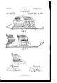
- Fig. 4. represents a side elevation showing the rear seat as reversed.
- Fig. 5 represents a longitudinal section on the line Y Y shown in Fig. l
- Fig. 6 represents a cross-section on the line Z Z shown in Fig. l.
- A is the bottom board; B, the toe-board; C C, the body sides, and D the hinged tail-board, inthe usual manner.
- E is the upright top'bar
- F is the upright center brace on which the front seat is supported.
- G is a semicircular guide-iron secured to said top bar and center brace,
- the front seat is divided transversely into two coequal sections H, pivoted at the front portion to the forward end of the center brace F, as shown in Fig. 1, to enable eit-her one of said front-seat portions to be swung outward to enable passengers to get easily into or out of the space back of said front seat.
- H H are guide-plates secured to the under sides of the front-seat sections H H and adapt' ed to receive the circle G, in this manner serving as guides in operating said front-seat portions and to limit their forward swinging m0- tions.
- the front-seat portions H H are normally secured together by means of a suitable locking device H, as shown in Fig. 8.
- I is a brace on which the rear seat K is pivseat is turned to the position shownin Figs.
- the back seat may be reversed to the position shown in Fig. 4 simply by swinging it half a revolution around the pivot 7c and locking it to the body sides by means of any suit able locking mechanism.
- Fig. 6 I have shown a very simple locking mechanism for this purpose, consisting, preferably, of a pivoted spring-pressed lock-lever L, pivoted -at Z to the side of the rear seat K and having in one end a projection Z', adapted to lock in a socket Ovin the body side C and having in its other end a push-button Z, projecting upward through a perforation in said rear seat K.
- testiuionywh'ereof I have signed my naine to this specification, in the presence oftwo subscribing witnesses,on this 31st day of December, A. D. 1890.
Landscapes
- Engineering & Computer Science (AREA)
- Aviation & Aerospace Engineering (AREA)
- Transportation (AREA)
- Mechanical Engineering (AREA)
- Chair Legs, Seat Parts, And Backrests (AREA)
Description
(No Model.) 2 Sheets-Sheet 1.
G. LfJ'OHNSON.
CARRIAGE SEAT.
' Patented Deo. l5, 1.891.
(No Model.)
2 Sheets-Sheet 2.
. IC. L. J0H1\s01\1.
CARRIAGE SEAT.
Patented Deo. 15,1891.
` UNITED STATES PATENT OFFICE.
CHARLES- L. JOHNSON, OF AMESBURY, MASSACHUSETTS.
CARRIAG E-SEAT.
SPECIFICATION forming part of Letters Patent No. 465,375, dated December 15, 1891.
Application filed February 5, 1891. Serial No. 380,286. (No model.)
To all whom t may concern,.-
Be it known that I, CHARLES L. JOHNSON, a citizen .of Sweden, and a resident of Amesbury, in the county of Essex and State of Masresents a cross-section on the line X X shown in Fig. 2. Fig. 4. represents a side elevation showing the rear seat as reversed. Fig. 5 represents a longitudinal section on the line Y Y shown in Fig. l, and Fig. 6 represents a cross-section on the line Z Z shown in Fig. l.
Similar letters refer to similar parts wherever they occur on the dierent parts of the drawings.
A is the bottom board; B, the toe-board; C C, the body sides, and D the hinged tail-board, inthe usual manner.
E is the upright top'bar, and F is the upright center brace on which the front seat is supported. G is a semicircular guide-iron secured to said top bar and center brace,
serving as a support and guide for the front seat. The front seat is divided transversely into two coequal sections H, pivoted at the front portion to the forward end of the center brace F, as shown in Fig. 1, to enable eit-her one of said front-seat portions to be swung outward to enable passengers to get easily into or out of the space back of said front seat.
H H are guide-plates secured to the under sides of the front-seat sections H H and adapt' ed to receive the circle G, in this manner serving as guides in operating said front-seat portions and to limit their forward swinging m0- tions.
`The front-seat portions H H are normally secured together by means of a suitable locking device H, as shown in Fig. 8.
I is a brace on which the rear seat K is pivseat is turned to the position shownin Figs.
l, 2, and 5.
The back seat may be reversed to the position shown in Fig. 4 simply by swinging it half a revolution around the pivot 7c and locking it to the body sides by means of any suit able locking mechanism. In Fig. 6 I have shown a very simple locking mechanism for this purpose, consisting, preferably, of a pivoted spring-pressed lock-lever L, pivoted -at Z to the side of the rear seat K and having in one end a projection Z', adapted to lock in a socket Ovin the body side C and having in its other end a push-button Z, projecting upward through a perforation in said rear seat K.
That I Wish to secure by Letters Patent and claim is 1. The combination, withqthe bottoni board of a carriage-body, of the upright top bar E, the upright center brace F, the semicircular guide-iron G, secured at the upper portion of the top bar and center brace, and the transversely-divided seat extending over the top bar and having its two sections pivoted at their front portions and each having a guideplate H', engagingthe semicircular guide-iron, substantially as described.
2. The combination, with the bottom board A, body sides C, and reversible rear seat K, of the upright top bar E, the upright center brace F, the seniicircular guide-iron Gr, secured to the upper portions of the top bar and center brace, and the transversely-divided front seat having its sections pivoted at their front portions and provided with guide-plates H', engaging the semicircular guide-iron, substantially as described.
In testiuionywh'ereof I have signed my naine to this specification, in the presence oftwo subscribing witnesses,on this 31st day of December, A. D. 1890.
CHARLES L. JOHNSON.
Witnesses:
ALBAN ANDREN, ALICE A. PERKINS.
Publications (1)
| Publication Number | Publication Date |
|---|---|
| US465375A true US465375A (en) | 1891-12-15 |
Family
ID=2534240
Family Applications (1)
| Application Number | Title | Priority Date | Filing Date |
|---|---|---|---|
| US465375D Expired - Lifetime US465375A (en) | Carriage-seat |
Country Status (1)
| Country | Link |
|---|---|
| US (1) | US465375A (en) |
-
0
- US US465375D patent/US465375A/en not_active Expired - Lifetime
Similar Documents
| Publication | Publication Date | Title |
|---|---|---|
| WO2010098196A1 (en) | Vehicle seat device | |
| US465375A (en) | Carriage-seat | |
| CZ2007612A3 (en) | Pivoted seat | |
| US177526A (en) | Improvement in vehicle-seats | |
| JP2009292403A (en) | Vehicle | |
| US1315031A (en) | Planooraph co | |
| US462101A (en) | Chusetts | |
| US519832A (en) | Seat for vehicles | |
| US180751A (en) | Improvement in car-seats | |
| US468275A (en) | Shifting seat for vehicles | |
| US464720A (en) | Carriage-body | |
| US160651A (en) | Improvement in shifting seats for carriages | |
| US283370A (en) | Coenelius batjee | |
| US415971A (en) | Vehicle-seat | |
| US300847A (en) | Jump-seat | |
| US438610A (en) | Shifting-seat vehicle | |
| US522976A (en) | Carriage | |
| US486469A (en) | Wheelbarrow | |
| US447752A (en) | Carriage | |
| US557195A (en) | Carriage | |
| US168386A (en) | Improvement in vehicle-seats | |
| US426158A (en) | Jump-seat carriage | |
| US560706A (en) | Caebiage | |
| US455738A (en) | Shifting seat for carriages | |
| US569794A (en) | Vehicle-body |