US4644909A - System for cooling internal combustion engines - Google Patents
System for cooling internal combustion engines Download PDFInfo
- Publication number
- US4644909A US4644909A US06/731,894 US73189485A US4644909A US 4644909 A US4644909 A US 4644909A US 73189485 A US73189485 A US 73189485A US 4644909 A US4644909 A US 4644909A
- Authority
- US
- United States
- Prior art keywords
- water
- cooling water
- water line
- motor
- engine
- Prior art date
- Legal status (The legal status is an assumption and is not a legal conclusion. Google has not performed a legal analysis and makes no representation as to the accuracy of the status listed.)
- Expired - Fee Related
Links
- 238000001816 cooling Methods 0.000 title claims abstract description 20
- 238000002485 combustion reaction Methods 0.000 title claims abstract description 8
- XLYOFNOQVPJJNP-UHFFFAOYSA-N water Substances O XLYOFNOQVPJJNP-UHFFFAOYSA-N 0.000 claims abstract description 90
- 239000000498 cooling water Substances 0.000 claims abstract description 43
- 239000000203 mixture Substances 0.000 claims abstract description 22
- 230000007246 mechanism Effects 0.000 claims abstract description 12
- 230000001105 regulatory effect Effects 0.000 abstract 1
- 230000004044 response Effects 0.000 description 5
- 230000009467 reduction Effects 0.000 description 3
- 230000006978 adaptation Effects 0.000 description 2
- 230000004075 alteration Effects 0.000 description 2
- 239000000446 fuel Substances 0.000 description 2
- 239000000463 material Substances 0.000 description 2
- 239000002184 metal Substances 0.000 description 2
- 230000004048 modification Effects 0.000 description 2
- 238000012986 modification Methods 0.000 description 2
- 230000008859 change Effects 0.000 description 1
- 238000010586 diagram Methods 0.000 description 1
- 230000000694 effects Effects 0.000 description 1
- 239000012530 fluid Substances 0.000 description 1
- 238000005461 lubrication Methods 0.000 description 1
- 238000013021 overheating Methods 0.000 description 1
- 230000000630 rising effect Effects 0.000 description 1
- 230000007704 transition Effects 0.000 description 1
- 238000010792 warming Methods 0.000 description 1
Images


Classifications
-
- F—MECHANICAL ENGINEERING; LIGHTING; HEATING; WEAPONS; BLASTING
- F01—MACHINES OR ENGINES IN GENERAL; ENGINE PLANTS IN GENERAL; STEAM ENGINES
- F01P—COOLING OF MACHINES OR ENGINES IN GENERAL; COOLING OF INTERNAL-COMBUSTION ENGINES
- F01P7/00—Controlling of coolant flow
- F01P7/14—Controlling of coolant flow the coolant being liquid
- F01P7/16—Controlling of coolant flow the coolant being liquid by thermostatic control
-
- F—MECHANICAL ENGINEERING; LIGHTING; HEATING; WEAPONS; BLASTING
- F16—ENGINEERING ELEMENTS AND UNITS; GENERAL MEASURES FOR PRODUCING AND MAINTAINING EFFECTIVE FUNCTIONING OF MACHINES OR INSTALLATIONS; THERMAL INSULATION IN GENERAL
- F16K—VALVES; TAPS; COCKS; ACTUATING-FLOATS; DEVICES FOR VENTING OR AERATING
- F16K11/00—Multiple-way valves, e.g. mixing valves; Pipe fittings incorporating such valves
- F16K11/02—Multiple-way valves, e.g. mixing valves; Pipe fittings incorporating such valves with all movable sealing faces moving as one unit
- F16K11/06—Multiple-way valves, e.g. mixing valves; Pipe fittings incorporating such valves with all movable sealing faces moving as one unit comprising only sliding valves, i.e. sliding closure elements
- F16K11/065—Multiple-way valves, e.g. mixing valves; Pipe fittings incorporating such valves with all movable sealing faces moving as one unit comprising only sliding valves, i.e. sliding closure elements with linearly sliding closure members
- F16K11/07—Multiple-way valves, e.g. mixing valves; Pipe fittings incorporating such valves with all movable sealing faces moving as one unit comprising only sliding valves, i.e. sliding closure elements with linearly sliding closure members with cylindrical slides
- F16K11/0716—Multiple-way valves, e.g. mixing valves; Pipe fittings incorporating such valves with all movable sealing faces moving as one unit comprising only sliding valves, i.e. sliding closure elements with linearly sliding closure members with cylindrical slides with fluid passages through the valve member
-
- F—MECHANICAL ENGINEERING; LIGHTING; HEATING; WEAPONS; BLASTING
- F16—ENGINEERING ELEMENTS AND UNITS; GENERAL MEASURES FOR PRODUCING AND MAINTAINING EFFECTIVE FUNCTIONING OF MACHINES OR INSTALLATIONS; THERMAL INSULATION IN GENERAL
- F16K—VALVES; TAPS; COCKS; ACTUATING-FLOATS; DEVICES FOR VENTING OR AERATING
- F16K11/00—Multiple-way valves, e.g. mixing valves; Pipe fittings incorporating such valves
- F16K11/02—Multiple-way valves, e.g. mixing valves; Pipe fittings incorporating such valves with all movable sealing faces moving as one unit
- F16K11/08—Multiple-way valves, e.g. mixing valves; Pipe fittings incorporating such valves with all movable sealing faces moving as one unit comprising only taps or cocks
- F16K11/085—Multiple-way valves, e.g. mixing valves; Pipe fittings incorporating such valves with all movable sealing faces moving as one unit comprising only taps or cocks with cylindrical plug
Definitions
- This invention relates to a system for cooling internal combustion engines, particularly to a cooling system in which the mixture ratio of the cooling water circulated through a radiator with the water circulated without passing through a radiator is controlled in accordance with the temperature of the cooling water supplied to the engine.
- thermo-valve operated in accordance with the water temperature.
- a wax-type thermostat valve is used as the thermo-valve.
- the conventional controlling system using such wax-type thermo-valve has drawbacks which result from some special characters of the wax-type thermostat. Namely, since the wax-type thermostat operates responding to the meltage of wax contained therein, tne time for the response requires inevitably a somewhat long time (about 80 sec. in general).
- the operation does not necessarily follow the rapid variation of conditions such as the engine load, and sometimes there are caused undesirable phenomena such as overheating at the time of going up a steep slope, a hot soak or a dead soak at the time of a sudden stop and an over-shoot at the time of a rapid start.
- undesirable phenomena such as overheating at the time of going up a steep slope, a hot soak or a dead soak at the time of a sudden stop and an over-shoot at the time of a rapid start.
- the thermostat is replaced with a thermostat for the cold area.
- there comes inevitably some aberration of the temperature of cooling water for instance, there is ordinarily an aberration of about ⁇ 3° C.
- the thermostat At the time of speed transition when the engine rotation is increasing rapidly, the thermostat is subjected to a strong fluid power and tends to over-open, which would decrease the temperature of the cooling water at the engine inlet excessively. Since the temperature for opening or closing the valve has to be fixed, it is impossible to choose an adequate water temperature according to or following the engine load, the HC amount in the exhaust gas or the fuel consumption rate. The wax contained in the thermostat, would leak out or be degraded during use. It takes often a long time to exhaust air from the valve at the time of pouring water thereinto, as the air-exhausting hole cannot but be rather small. On the contrary, the time for warming up the engine becomes long in a cold area, as the cooling water in the radiatorside often flows into the valve from the above a small airexhausting hole during engine stop.
- the object of the present invention is to provide an improved system for controlling the temperature of cooling water, which can resolve the foregoing problems of the wax type thermostat valve, especially can avoid the inconvenience of the time delay of valve operation.
- the valve is controlled by a motor which operates in response to the signal from a water-temperature sensor.
- the motor-driven valve is arranged before a water pump, and the water temperature sensor is arranged at a position between the water pump and the cooling water inlet to the engine.
- a control means such as a control circuit is arranged in the system.
- the control circuit receives the signal of the detected temperature from the sensor and generates a signal for determining the rotation direction and the rotation degree of the motor, whereby the opening-closing operation of the valve is controlled in accordance with the water temperature.
- valves besides the valves having such structures as mentioned in the embodiments, may be used, provided that they are suitable for electrical opening-closing operation.
- the valve body may be placed either only at a position connecting the main water line with the by-pass water line or in each of the two water lines.
- the motor for driving the valve mechanism a direct current motor or a stepping motor can be used.
- the use of the stepping motor has an effect to reduce the size of the valve structure.
- the temperature sensor such as a thermo-couple or a thermistor is used.
- various sensors which have a linear output character can be used as the sensor for the present invention.
- the sensors which do not necessarily have a linear output character can be also used, in the case where the rate of the valve-opening is set up so as to compensate such sensor character.
- valve mechanism and controlling means it is possible to operate the cooling system so that the water from the main water line and the water from the by-pass water line are mixed up at an optional ratio, always following the change of various conditions such as engine load, etc. without being accompanied with the time delay as in the wax-type thermostat.
- the temperature of the cooling water at the inlet to the engine is maintained always at a desired degree and an undesirable phenomena such as an over-shoot with hunting can be avoided.
- FIG. 1 shows a schematic outline of the conventional cooling system for a water-cooled engine.
- FIG. 2 shows a schematic outline of another model of the conventional cooling system for a water-cooled engine.
- FIG. 3 shows a schematic outline of the cooling system for a water-cooled engine, in accordance with the present invention.
- FIG. 4(a) through FIG. 4(c) show one embodiment of the motor-driven mixture valve in accordance with the present invention, FIG. 4(a) showing the side sectional view, FIG. 4(b) showing a partial cross-sectional view taken on the line X--X in FIG. 4(a), and FIG. 4(c) showing the perspective view of the spool for the motor-driven valve.
- FIG. 5 shows a controlling circuit for the embodiment of FIG. 4.
- FIG. 6(a) through FIG. 6(d) show another embodiment of the motor-driven valve in accordance with the present invention, FIG. 6(a) showing the plan view, FIG. 6(b) showing the cross-sectional view taken on the line Y--Y in FIG. 6(a), FIG. 6(c) showing the cross-sectional view taken on the line Z--Z in FIG. 6(b)/and FIG. 6(d) showing the valve spool.
- FIG. 7 shows a controlling circuit for the motor-driven valve of FIG. 6.
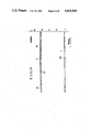
- FIG. 8 shows the temperature characteristic curve of the conventional cooling system shown in FIG. 1.
- FIG. 9 shows the temperature characteristic curve of the cooling system in accordance with the present invention, shown in FIG. 3.
- FIG. 1 which shows a model of the conventional cooling system for a water-cooled engine using a wax-type thermostat
- the cooling water circulates in a main water line 3 connecting an engine 1 and a radiator 2 for radiating the engine heat into the air.
- a by-pass water line 4 is provided, being diverged from the main water line 3 in order to circulate a part of the cooling water to the inlet of the engine directly without passing through the radiator 2.
- the intercommunication between the main water line 3 and the by-pass water line 4 is made by a mixture valve 5 using a wax-type thermostat, and the extent of the intercommunication depends on the opening degree of the valve in response to the temperature detected by the thermostat.
- the mixture of the water from the main water line 3 and the water from the bypass water line 4 was sent to the engine 1 by a water pump 7.
- FIG. 2 which shows another model of the conventional cooling system
- the distribution valve 6 using a wax-type thermostat is arranged at a position close to the water outlet of the engine, contrary to the model in FIG. 1 in which the mixture valve is arranged at the downstream-side of the by-pass water line.
- the mixture ratio between the water from the main water line 3 and the water from the by-pass water line 4 depends on the opening degree of the valve responding to the temperature detected by the thermostat.
- FIG. 3 shows a schematic outline of the cooling system of the present invention
- the engine 1, the radiator 2, the main water line 3, the by-pass water line 4 and the water pump 7 are arranged as same as in the conventional system.
- a motordriven mixture valve 8, a water temperature sensor 9 and a controller 10 are newly provided in this system.
- the purpose of employing these members are as stated in the foregoing, and the detailed structure and function of them will be explained in the following.
- a valve body 21 has a clutching mechanism which converts the rotation of a direct current motor 23 to the up-down movement of a shaft 27 by the function of a gear box 22 for reducing the rotation speed of the direct current motor 23.
- a connector 25 connected electrically to the direct current motor 23.
- the direct current motor 23, the reduction gear box 22 and the valve body 21 constitute a mixture valve.
- a spool 26 which has a cylindrical shape as shown in FIG. 4(c) and is fixed to the shaft 27, can make a sliding up-and-down movement between a radiator-side opening A and a by-pass-side opening B.
- This movement of the spool 26 can vary the opening degree of the radiator-side opening A and the by-pass-side opening B, thereby to control the mixture ratio of the water supplied from the main water line to the water supplied from the by-pass water line.
- FIG. 4(b) its right-side portion shows a full-opened situation of the by-pass water line, and its left-side portion shows a full-opened situation of the main water line.
- a controller usable to the valve of FIG. 4 is shown in the circuit diagram of FIG. 5.
- a CA-type thermo-couple is used as the water temperature sensor provided at a position close to the water inlet to the engine. If the output of the CA-type thermo-couple is of a non-linear character, it is input to a temperature compensation amplifier 32. It is of course possible that the temperature compensation amplifier 32 can be omitted in some cases, considering the character of the sensor or the thermo-couple.
- the output of the temperature compensation amplifier 32 is input to a valve-opening comparator 34 or to a valve-closing comparator 35, after being amplified to an adequate level by an amplifier 33.
- a valve-opening temperature determined by the input voltage VT 1 and the resistance value of a resistor R 1 , is set up for the valve-opening comparator 34, while a valve-closing temperature is determined by the input voltage VT 2 and the resistance value of a resistor R 2 , is set up for the valveclosing comparator 35. It is desirable that the difference between the valve-opening temperature and the valve-closing temperature is about 2° C. through 3° C., as a difference more than that range might cause a hunting of the water temperature.
- the outputs of the valve-opening comparator 34 and the valve-closing comparator 35 are conducted to an AND-gate AND 1 and an AND-gate AND 2 respectively to open or close them.
- the output of a square-wave generator 36 is also conducted to the AND-gate AND 1 and the AND-gate AND 2 . Further, the limit signal of a valve-opening limit switch L 1 , which operates when the movement of the spool 26 in the valve body 21 reaches the lower limit, is input to the AND-gate AND 1 , while the limit signal of a valve-closing limit switch L 2 which operates when the movement of the spool 26 in the valve body 21 reaches the upper limit is input to the AND-gate AND 2 .
- valve-opening limit switch L 1 and the valve-closing limit switch L 2 are closed; and the H (High) level is conducted from a power supply +Vcc to the AND-gates AND 1 and AND 2 through a resistor R 3 to open the AND-gates AND 1 and AND 2 .
- the valve-opening limit switch L 1 or the valve-closing limit switch L 2 is opened and AND-gate AND 1 or the AND-gate AND 2 is closed.
- a motor-driving circuit 37 rotates the direct current motor 23 and moves the spool 26 downwardly when the valve-closing signal is generated, namely, when the output of the square wave generator 36 is supplied to the motor 23 through the AND-gate AND 1 .
- the motor-driving circuit 37 rotates the motor 23 reversely and moves the spool 26 upwardly.
- the output of the CA-type thermo-couple 31 increases and the output of the valve-opening comparator 34 becomes an H level. Since the square-wave generator 36 is always in a generating situation and the valve-opening limit switch L 1 is ordinarily closed, the AND-gate AND 1 opens and the output of the square-wave generator 36 is input to the motor-driving circuit 37 when the output of the valve-opening comparator becomes the H level.
- the direct current motor 23 rotates steppingly in accordance with the output of the square wave generator 36, thereby to conduct the cooling water in the radiatorside opening A to the engine-side opening C through the spool 26. This causes the reduction of the volume of the cooling water flowing from the by-pass-side opening B to the engine-side opening C and the increase of the volume of the cooling water flowing from the radiatorside opening A to the engine-side opening C.
- the AND-gate AND 1 is closed by the function of the valve opening limit switch L 1 , and the direct current motor 23 ceases to rotate.
- the output of the CA-type thermo-couple 31 is reduced and the output of the valve-closing comparator 35 becomes an H level. Since the valve-closing limit switch L 2 is closed ordinarily, the AND-gate AND 2 opens and the direct current motor 23 rotates steppingly so as to elevate the spool 26. This reduces the opening degree of the radiator-side opening A and increases the opening degree of the by-pass-side opening B, whereby the ratio of the cooling water flowing through the by-pass water line is increased. When the movement of the spool 26 reaches the upper limit, the AND-gate AND 2 is closed by the function of the valve-closing limit switch L 2 , and the direct current motor 23 ceases to rotate.
- the water-cooled engine is cooled through the control of the opening degree of the mixture valve connected to the direct current motor which is driven in accordance with the output of the CA-type thermocouple. Therefore, if the temperature for opening or closing the valve is controlled by such means as a microprocessor so that it corresponds to the HC amount in the exhaust gas or the fuel consumption rate, the temperature of the engine can be controlled so as to be always at a desired condition.
- a rotary spool 45 fixed to the shaft of a gear box 44, for reducing the rotation speed of a stepping motor 43.
- the rotary movement of the rotary spool 45 causes a spool rotation limit member 47 having a same axis with the rotary spool to such a limit switch L 3 or L 4 (in FIG. 7) to detect the limit of the rightward or leftward rotary movement.
- the rotary spool 45 has an opening 49 of a triangle shape on the circumference.
- the axis portion of the rotary spool 45 is sealed with an O-ring 48 to prevent the water leakage to the side of the reduction gear box 44, and a bush 46 is arranged at the one end of the axis portion.
- FIG. 6(b) and (c) show a situation in which the mixture valve makes the cooling water to flow to the engine-side opening C mainly from the radiator-side opening A.
- a relatively little volume of water is conducted from the by-pass-side opening B to the engine-side opening C through the end portion of the opening 49 of the rotary spool 45.
- the shape and the size of the opening 49 should be determined by such factors as the resistance in the main water line including a radiator portion, the resistance in the by-pass water line or in the engine, the capacity of the water pump, and the power of the engine.
- the mixture valve of FIG. 6 can be controlled by such control circuit as mentioned in FIG. 7.
- a thermistor 51 is arranged at a position close to the inlet to the engine, as a water temperature sensor. It is desirable to use the thermistor after treating it so that it can bear the use as the water temperature sensor, for instance, by inserting it into a metal case and filling up the case with plastic materials, because the thermistor is easy to be destroyed if it is used in a bare condition. However, it is necessary to fully take into account the character of the metal case or the filling materials and the assembling conditions of the sensor, so that the treatment of the thermistor does not excessively reduce the response capability of the sensor.
- the thermistor 51 is connected to a power supply +Vcc through a resistor R 4 , and the output having a linear character responding to the variation of temperature is input to a valve-opening comparator 53 and a valve closing comparator 54 after being amplified by an amplifier 52.
- the valve-opening temperature which is determined by the input voltage VT 1 and the resistance valve of the resistor R 1 , is set up for the valve-opening comparator 53, while the valve-closing temperature, which is determined by the input voltage VT 2 and the resistance valve of the resistor R 2 , is set up for the valve-closing comparator 54.
- the output of the valve-opening comparator 53 is conducted to an AND-gate AND 3 so as to open a leftward rotation limit switch L 3 and close the AND-gate AND 3 , when the rotary movement of the rotary spool 45 reaches the leftward rotation limit.
- the output of the valve-closing comparator 54 is conducted to an AND-gate AND 4 so as to open a rightward rotation limit switch L 4 and close the AND-gate AND 4 when the rotary movement of the rotary spool 45 reaches the rightward rotation limit.
- the outputs of the AND-gates AND 3 and AND 4 are conducted to a distributor 56 with the output of a clock-pulse generator 55.
- the distributor 56 consisting of such members as a shift-resistor generates an exciting-phase signal for deciding the rotation direction of the stepping motor 58.
- the output of the clockpulse generator determines the driving-frequency of a stepping motor 58.
- the output of the distributor 56 is conducted to the motor-driving circuit 57 and excites a phase necessary to cause a rightward or leftward rotation of the stepping motor and to make the stepping motor 58 to rotate by a necessary angle.
- the stepping motor 58 and the rotary spool 45 are interconnected as mentioned in FIG.
- the rotary spool 45 rotates in accordance with the rotation of the stepping motor 58, whereby the cooling water from the radiator-side opening A and the cooling water from the by-pass-side opening B are mixed at an optional ratio and sent to the engine-side opening C.
- the stepping motor 58 rotates in accordance with the output of the AND-gate AND 3 or AND 4 and causes the rotation of the rotary spool 45 by an angle necessary to mix the water from the main water line with the water from the by-pass water line in an optional ratio.
- FIG. 8 shows the temperature characteristic curves of the engine cooling system of FIG. 1 under a running condition of 40 km/h with 4th speed.
- the curve H indicates the temperature at the engine head;
- the curve E/O indicates the temperature at the outlet from the engine;
- the curve E/I indicates the temperature at the inlet to the engine;
- the curve R/I indicates the temperature at the inlet to the radiator,
- the curve R/O indicates the temperature at the outlet from the radiator, and
- the curve T indicates the temperature of air detected by the sensor.
- the lower end point in the R/O curve shows a sharp temperature falling in the main water line 3 resulting from the closing of the wax-type thermostat.
- FIG. 9 shows the temperature characteristic curves of the engine cooling system in accordance with the present invention, in the case where the valve-opening temperature is set up to be 93° C. It will be understood that the temperatures at each portion of the cooling water line show only a little variation.
Landscapes
- Engineering & Computer Science (AREA)
- General Engineering & Computer Science (AREA)
- Mechanical Engineering (AREA)
- Chemical & Material Sciences (AREA)
- Combustion & Propulsion (AREA)
- Electrically Driven Valve-Operating Means (AREA)
- Temperature-Responsive Valves (AREA)
- Control Of Temperature (AREA)
Abstract
Description
Claims (4)
Applications Claiming Priority (2)
| Application Number | Priority Date | Filing Date | Title |
|---|---|---|---|
| JP59-93569 | 1984-05-10 | ||
| JP59093569A JPS60237116A (en) | 1984-05-10 | 1984-05-10 | Method and device of cooling control in engine |
Publications (1)
| Publication Number | Publication Date |
|---|---|
| US4644909A true US4644909A (en) | 1987-02-24 |
Family
ID=14085882
Family Applications (1)
| Application Number | Title | Priority Date | Filing Date |
|---|---|---|---|
| US06/731,894 Expired - Fee Related US4644909A (en) | 1984-05-10 | 1985-05-08 | System for cooling internal combustion engines |
Country Status (2)
| Country | Link |
|---|---|
| US (1) | US4644909A (en) |
| JP (1) | JPS60237116A (en) |
Cited By (38)
| Publication number | Priority date | Publication date | Assignee | Title |
|---|---|---|---|---|
| US5174254A (en) * | 1990-12-28 | 1992-12-29 | J. Eberspacher | Coolant circuit with a heater for a vehicle engine |
| US5458096A (en) * | 1994-09-14 | 1995-10-17 | Hollis; Thomas J. | Hydraulically operated electronic engine temperature control valve |
| US5463986A (en) * | 1994-09-14 | 1995-11-07 | Hollis; Thomas J. | Hydraulically operated restrictor/shutoff flow control valve |
| US5467745A (en) * | 1994-09-14 | 1995-11-21 | Hollis; Thomas J. | System for determining the appropriate state of a flow control valve and controlling its state |
| US5669335A (en) * | 1994-09-14 | 1997-09-23 | Thomas J. Hollis | System for controlling the state of a flow control valve |
| US5727729A (en) * | 1994-06-09 | 1998-03-17 | Rover Group Limited | Combined bypass and thermostat assembly |
| US5743721A (en) * | 1996-04-30 | 1998-04-28 | Itt Automotive Electrical Systems, Inc. | Blower assembly having integral air flow cooling duct |
| DE19809123A1 (en) * | 1998-03-04 | 1999-09-16 | Daimler Chrysler Ag | Water pump for the cooling circuit of an internal combustion engine |
| DE19809124A1 (en) * | 1998-03-04 | 1999-09-16 | Daimler Chrysler Ag | Control device for the cooling and heating circuit of an internal combustion engine |
| WO2000025007A1 (en) * | 1998-10-27 | 2000-05-04 | Daimlerchrysler Ag | Control device for the cooling circuit of an internal combustion engine |
| FR2796100A1 (en) | 1999-07-10 | 2001-01-12 | Daimler Chrysler Ag | CONTROL DEVICE FOR THE COOLING AND HEATING CIRCUIT OF AN INTERNAL COMBUSTION ENGINE |
| FR2800125A1 (en) * | 1999-10-20 | 2001-04-27 | Coutier Moulage Gen Ind | System for managing the flow of cooling liquid in cooling circuit in motor vehicle comprises control and distribution modules with temperature sensor and control flap to selectively allow the cooling fluid to enter one circuit or another |
| DE10012197A1 (en) * | 2000-03-13 | 2001-09-20 | Behr Thermot Tronik Gmbh & Co | Thermal management system for motor vehicle with coolant circuit and air conditioning system uses section of condenser as refrigerant to coolant heat exchanger |
| RU2204030C1 (en) * | 2001-09-03 | 2003-05-10 | Открытое акционерное общество "Чебоксарское научно-производственное приборостроительное предприятие "ЭЛАРА" | Internal combustion engine cooling liquid temperature regulator |
| US20030217775A1 (en) * | 2002-03-01 | 2003-11-27 | Cory Cousineau | Fluid valve |
| EP1126177A3 (en) * | 2000-02-16 | 2003-12-17 | WILO GmbH | Electric hydraulic interface |
| EP1126178A3 (en) * | 2000-02-16 | 2003-12-17 | WILO GmbH | Control system for pump valve unit |
| EP1270893A3 (en) * | 2001-06-21 | 2006-01-04 | Aisan Kogyo Kabushiki Kaisha | Engine cooling system |
| DE102008035961A1 (en) | 2008-07-31 | 2010-02-04 | Schaeffler Kg | Thermal management module of the cooling system of an internal combustion engine |
| DE102009014038A1 (en) | 2009-03-19 | 2010-09-23 | Schaeffler Technologies Gmbh & Co. Kg | Heat management module for cooling system of internal combustion engine, has supply connection for cooling water of bypass cycle, where supply connection is arranged at valve housing |
| DE102009014048A1 (en) | 2009-03-19 | 2010-09-23 | Schaeffler Technologies Gmbh & Co. Kg | Heat management module for cooling system of internal combustion engine, has supply connection for cooling water of bypass cycle, where supply connection is arranged at valve housing |
| DE102009014047A1 (en) | 2009-03-19 | 2010-09-23 | Schaeffler Technologies Gmbh & Co. Kg | Control valve for controlling a coolant circuit of an internal combustion engine, has two supply connections, where former supply connection is arranged at valve housing for cooling water of bypass cycle |
| DE102009014050A1 (en) | 2009-03-19 | 2010-09-23 | Schaeffler Technologies Gmbh & Co. Kg | Heat management module for cooling system of internal combustion engine, has supply connection for cooling water of bypass cycle, where supply connection is arranged at valve housing |
| DE102009025351A1 (en) | 2009-06-18 | 2010-12-23 | Schaeffler Technologies Gmbh & Co. Kg | Control valve for controlling coolant circuit of internal combustion engine, has sealing element arranged in hole of valve housing such that sealing system of sealing element acts on valve element and/or valve housing |
| DE102009025360A1 (en) | 2009-06-18 | 2010-12-23 | Schaeffler Technologies Gmbh & Co. Kg | Control valve for controlling coolant circuit of internal combustion engine, has valve housing with hole provided as feed connection, and sealing element sealing coolant flow path in axial and/or radial direction and formed in nozzle shape |
| DE102009025341A1 (en) | 2009-06-18 | 2010-12-23 | Schaeffler Technologies Gmbh & Co. Kg | Control valve for regulating coolant circuit of internal combustion engine, has two feed connections arranged on valve housing for cooling water of bypass circuit and for cooling water of cooling circuit |
| US20120060954A1 (en) * | 2010-09-13 | 2012-03-15 | Kia Motors Corporation | Three-way valve integrated with radiator |
| DE102011083803A1 (en) | 2011-09-30 | 2013-04-04 | Schaeffler Technologies AG & Co. KG | Control valve for use as rotary valve in refrigerant circuit of combustion engine, has sealing elements supported with outer contour complementary to contact zone of valve element to form common sealing surfaces |
| DE102012211116A1 (en) | 2012-06-28 | 2014-01-02 | Schaeffler Technologies AG & Co. KG | Thermal management module with multi-part housing |
| US20140093393A1 (en) * | 2011-06-22 | 2014-04-03 | Toyota Jidosha Kabushiki Kaisha | Control device for electric water pump |
| DE102013222825A1 (en) | 2013-11-11 | 2015-05-13 | Schaeffler Technologies Gmbh & Co. Kg | Single bearing of a rotary valve shaft with reduced radial play and adapted guide length |
| DE102013222157A1 (en) | 2013-10-31 | 2015-05-21 | Schaeffler Technologies AG & Co. KG | Guiding geometry within a rotary valve of a thermal management module |
| DE102014206480A1 (en) | 2014-04-04 | 2015-10-08 | Schaeffler Technologies AG & Co. KG | Thermal management module combined with a thermostatic control |
| DE102014206529A1 (en) | 2014-04-04 | 2015-10-08 | Schaeffler Technologies AG & Co. KG | Thermal management module with rotary valve technology |
| DE102014214323B3 (en) * | 2014-07-23 | 2015-12-17 | Schaeffler Technologies AG & Co. KG | End position control for a thermal management module |
| DE102014211641A1 (en) * | 2014-06-18 | 2015-12-24 | Schaeffler Technologies AG & Co. KG | Thermal management module with position control of the rotary valve |
| DE102014211639A1 (en) | 2014-06-18 | 2015-12-24 | Schaeffler Technologies AG & Co. KG | Sensor system for a thermal management module |
| WO2020145921A3 (en) * | 2019-01-10 | 2020-11-12 | Kirpart Otomotiv Parcalari Sanayi Ve Ticaret A.S | A smart thermal management module for engine cooling |
Families Citing this family (2)
| Publication number | Priority date | Publication date | Assignee | Title |
|---|---|---|---|---|
| JP2690894B2 (en) * | 1987-04-27 | 1997-12-17 | 三菱重工業株式会社 | Internal combustion engine cooling system |
| IT1291190B1 (en) * | 1997-03-13 | 1998-12-29 | Gate Spa | Cooling system for an internal combustion engine, particularly for motor vehicles |
Citations (4)
| Publication number | Priority date | Publication date | Assignee | Title |
|---|---|---|---|---|
| US4388913A (en) * | 1980-01-17 | 1983-06-21 | Robert Bosch Gmbh | Adjustment device for rotary angle adjustment |
| US4425878A (en) * | 1980-07-10 | 1984-01-17 | Nordstjernan Ab | Internal combustion engine cooling method and device |
| US4453700A (en) * | 1981-02-05 | 1984-06-12 | Nippondenso Co., Ltd. | Fluid control valve assembly |
| US4550693A (en) * | 1983-09-09 | 1985-11-05 | Behr-Thomson Dehnstoffregler Gmbh | Temperature control arrangement for combustion engine |
-
1984
- 1984-05-10 JP JP59093569A patent/JPS60237116A/en active Pending
-
1985
- 1985-05-08 US US06/731,894 patent/US4644909A/en not_active Expired - Fee Related
Patent Citations (4)
| Publication number | Priority date | Publication date | Assignee | Title |
|---|---|---|---|---|
| US4388913A (en) * | 1980-01-17 | 1983-06-21 | Robert Bosch Gmbh | Adjustment device for rotary angle adjustment |
| US4425878A (en) * | 1980-07-10 | 1984-01-17 | Nordstjernan Ab | Internal combustion engine cooling method and device |
| US4453700A (en) * | 1981-02-05 | 1984-06-12 | Nippondenso Co., Ltd. | Fluid control valve assembly |
| US4550693A (en) * | 1983-09-09 | 1985-11-05 | Behr-Thomson Dehnstoffregler Gmbh | Temperature control arrangement for combustion engine |
Cited By (63)
| Publication number | Priority date | Publication date | Assignee | Title |
|---|---|---|---|---|
| US5174254A (en) * | 1990-12-28 | 1992-12-29 | J. Eberspacher | Coolant circuit with a heater for a vehicle engine |
| US5727729A (en) * | 1994-06-09 | 1998-03-17 | Rover Group Limited | Combined bypass and thermostat assembly |
| US5458096A (en) * | 1994-09-14 | 1995-10-17 | Hollis; Thomas J. | Hydraulically operated electronic engine temperature control valve |
| US5463986A (en) * | 1994-09-14 | 1995-11-07 | Hollis; Thomas J. | Hydraulically operated restrictor/shutoff flow control valve |
| US5467745A (en) * | 1994-09-14 | 1995-11-21 | Hollis; Thomas J. | System for determining the appropriate state of a flow control valve and controlling its state |
| US5505164A (en) * | 1994-09-14 | 1996-04-09 | Hollis; Thomas J. | Temperature control system utilizing an electronic engine temperature control valve |
| US5669335A (en) * | 1994-09-14 | 1997-09-23 | Thomas J. Hollis | System for controlling the state of a flow control valve |
| US5954488A (en) * | 1996-04-30 | 1999-09-21 | Valeo, Inc. | Blower assembly having integral air flow cooling duct |
| US5743721A (en) * | 1996-04-30 | 1998-04-28 | Itt Automotive Electrical Systems, Inc. | Blower assembly having integral air flow cooling duct |
| DE19809123A1 (en) * | 1998-03-04 | 1999-09-16 | Daimler Chrysler Ag | Water pump for the cooling circuit of an internal combustion engine |
| DE19809124A1 (en) * | 1998-03-04 | 1999-09-16 | Daimler Chrysler Ag | Control device for the cooling and heating circuit of an internal combustion engine |
| EP0940566A3 (en) * | 1998-03-04 | 2000-03-01 | DaimlerChrysler AG | Control device for the cooling - and heating circuit of an internal combustion engine |
| EP0940565A3 (en) * | 1998-03-04 | 2000-03-01 | DaimlerChrysler AG | Water pump for the cooling circuit of an internal combustion engine |
| DE19809123B4 (en) * | 1998-03-04 | 2005-12-01 | Daimlerchrysler Ag | Water pump for the cooling circuit of an internal combustion engine |
| US6257177B1 (en) | 1998-03-04 | 2001-07-10 | Daimlerchrysler Ag | Water pump for the cooling circuit of an internal combustion engine |
| US6164248A (en) * | 1998-03-04 | 2000-12-26 | Daimlerchrysler Ag | Control device for the coolant and heating circulation circuit of an internal combustion engine |
| DE19849492A1 (en) * | 1998-10-27 | 2000-05-11 | Daimler Chrysler Ag | Control device for a cooling circuit of an internal combustion engine |
| DE19849492B4 (en) * | 1998-10-27 | 2005-12-22 | Daimlerchrysler Ag | Control device for a cooling circuit of an internal combustion engine |
| WO2000025007A1 (en) * | 1998-10-27 | 2000-05-04 | Daimlerchrysler Ag | Control device for the cooling circuit of an internal combustion engine |
| FR2796100A1 (en) | 1999-07-10 | 2001-01-12 | Daimler Chrysler Ag | CONTROL DEVICE FOR THE COOLING AND HEATING CIRCUIT OF AN INTERNAL COMBUSTION ENGINE |
| DE19932313A1 (en) * | 1999-07-10 | 2001-01-18 | Daimler Chrysler Ag | Controller for internal combustion engine cooling, heating circuit has rotary disc on valve housing, drive unit, cooling line openings in housing for delivery to supply pump and sub-circuits |
| US6371060B1 (en) | 1999-07-10 | 2002-04-16 | Daimlerchrysler Ag | Control device for the cooling and heating circuit of an internal combustion engine |
| FR2800125A1 (en) * | 1999-10-20 | 2001-04-27 | Coutier Moulage Gen Ind | System for managing the flow of cooling liquid in cooling circuit in motor vehicle comprises control and distribution modules with temperature sensor and control flap to selectively allow the cooling fluid to enter one circuit or another |
| EP1126178A3 (en) * | 2000-02-16 | 2003-12-17 | WILO GmbH | Control system for pump valve unit |
| EP1126177A3 (en) * | 2000-02-16 | 2003-12-17 | WILO GmbH | Electric hydraulic interface |
| DE10012197A1 (en) * | 2000-03-13 | 2001-09-20 | Behr Thermot Tronik Gmbh & Co | Thermal management system for motor vehicle with coolant circuit and air conditioning system uses section of condenser as refrigerant to coolant heat exchanger |
| DE10012197B4 (en) * | 2000-03-13 | 2012-02-02 | Behr Thermot-Tronik Gmbh | Thermal management for a motor vehicle with a coolant circuit and an air conditioning system |
| EP1270893A3 (en) * | 2001-06-21 | 2006-01-04 | Aisan Kogyo Kabushiki Kaisha | Engine cooling system |
| RU2204030C1 (en) * | 2001-09-03 | 2003-05-10 | Открытое акционерное общество "Чебоксарское научно-производственное приборостроительное предприятие "ЭЛАРА" | Internal combustion engine cooling liquid temperature regulator |
| US20030217775A1 (en) * | 2002-03-01 | 2003-11-27 | Cory Cousineau | Fluid valve |
| WO2010012563A1 (en) * | 2008-07-31 | 2010-02-04 | Schaeffler Kg | Heat management module of the cooling system of an internal combustion engine |
| CN102112715B (en) * | 2008-07-31 | 2013-05-29 | 谢夫勒科技股份两合公司 | Heat management module of cooling system of internal combustion engine |
| US8807096B2 (en) * | 2008-07-31 | 2014-08-19 | Schaeffler Technologies AG & Co. KG | Heat management module of the cooling system of an internal combustion engine |
| DE102008035961A1 (en) | 2008-07-31 | 2010-02-04 | Schaeffler Kg | Thermal management module of the cooling system of an internal combustion engine |
| US20110162595A1 (en) * | 2008-07-31 | 2011-07-07 | Schaeffler Technologies Gmbh & Co. Kg | Heat management module of the cooling system of an internal combustion engine |
| CN102112715A (en) * | 2008-07-31 | 2011-06-29 | 谢夫勒科技有限两合公司 | Heat management module of cooling system of internal combustion engine |
| DE102009014050A1 (en) | 2009-03-19 | 2010-09-23 | Schaeffler Technologies Gmbh & Co. Kg | Heat management module for cooling system of internal combustion engine, has supply connection for cooling water of bypass cycle, where supply connection is arranged at valve housing |
| DE102009014047A1 (en) | 2009-03-19 | 2010-09-23 | Schaeffler Technologies Gmbh & Co. Kg | Control valve for controlling a coolant circuit of an internal combustion engine, has two supply connections, where former supply connection is arranged at valve housing for cooling water of bypass cycle |
| DE102009014038B4 (en) * | 2009-03-19 | 2015-07-02 | Schaeffler Technologies AG & Co. KG | Thermal management module with prismatic control slide |
| DE102009014038A1 (en) | 2009-03-19 | 2010-09-23 | Schaeffler Technologies Gmbh & Co. Kg | Heat management module for cooling system of internal combustion engine, has supply connection for cooling water of bypass cycle, where supply connection is arranged at valve housing |
| DE102009014048A1 (en) | 2009-03-19 | 2010-09-23 | Schaeffler Technologies Gmbh & Co. Kg | Heat management module for cooling system of internal combustion engine, has supply connection for cooling water of bypass cycle, where supply connection is arranged at valve housing |
| DE102009025360A1 (en) | 2009-06-18 | 2010-12-23 | Schaeffler Technologies Gmbh & Co. Kg | Control valve for controlling coolant circuit of internal combustion engine, has valve housing with hole provided as feed connection, and sealing element sealing coolant flow path in axial and/or radial direction and formed in nozzle shape |
| DE102009025341A1 (en) | 2009-06-18 | 2010-12-23 | Schaeffler Technologies Gmbh & Co. Kg | Control valve for regulating coolant circuit of internal combustion engine, has two feed connections arranged on valve housing for cooling water of bypass circuit and for cooling water of cooling circuit |
| DE102009025351A1 (en) | 2009-06-18 | 2010-12-23 | Schaeffler Technologies Gmbh & Co. Kg | Control valve for controlling coolant circuit of internal combustion engine, has sealing element arranged in hole of valve housing such that sealing system of sealing element acts on valve element and/or valve housing |
| DE102009025351B4 (en) * | 2009-06-18 | 2015-06-11 | Schaeffler Technologies AG & Co. KG | Control valve for controlling a coolant circuit of an internal combustion engine |
| US20120060954A1 (en) * | 2010-09-13 | 2012-03-15 | Kia Motors Corporation | Three-way valve integrated with radiator |
| US8485226B2 (en) * | 2010-09-13 | 2013-07-16 | Hyundai Motor Company | Three-way valve integrated with radiator |
| US20140093393A1 (en) * | 2011-06-22 | 2014-04-03 | Toyota Jidosha Kabushiki Kaisha | Control device for electric water pump |
| US9695827B2 (en) * | 2011-06-22 | 2017-07-04 | Toyota Jidosha Kabushiki Kaisha | Control device for electric water pump |
| DE102011083803A1 (en) | 2011-09-30 | 2013-04-04 | Schaeffler Technologies AG & Co. KG | Control valve for use as rotary valve in refrigerant circuit of combustion engine, has sealing elements supported with outer contour complementary to contact zone of valve element to form common sealing surfaces |
| WO2014000995A1 (en) | 2012-06-28 | 2014-01-03 | Schaeffler Technologies AG & Co. KG | Thermal management module with multi-part housing |
| DE102012211116A1 (en) | 2012-06-28 | 2014-01-02 | Schaeffler Technologies AG & Co. KG | Thermal management module with multi-part housing |
| DE102013222157A1 (en) | 2013-10-31 | 2015-05-21 | Schaeffler Technologies AG & Co. KG | Guiding geometry within a rotary valve of a thermal management module |
| DE102013222825A1 (en) | 2013-11-11 | 2015-05-13 | Schaeffler Technologies Gmbh & Co. Kg | Single bearing of a rotary valve shaft with reduced radial play and adapted guide length |
| WO2015149764A1 (en) | 2014-04-04 | 2015-10-08 | Schaeffler Technologies AG & Co. KG | Heat management module combined with thermostatic control |
| DE102014206529A1 (en) | 2014-04-04 | 2015-10-08 | Schaeffler Technologies AG & Co. KG | Thermal management module with rotary valve technology |
| DE102014206480A1 (en) | 2014-04-04 | 2015-10-08 | Schaeffler Technologies AG & Co. KG | Thermal management module combined with a thermostatic control |
| DE102014211641A1 (en) * | 2014-06-18 | 2015-12-24 | Schaeffler Technologies AG & Co. KG | Thermal management module with position control of the rotary valve |
| DE102014211639A1 (en) | 2014-06-18 | 2015-12-24 | Schaeffler Technologies AG & Co. KG | Sensor system for a thermal management module |
| DE102014211641B4 (en) | 2014-06-18 | 2021-07-15 | Schaeffler Technologies AG & Co. KG | Thermal management module with position control of the rotary valve |
| DE102014211639B4 (en) | 2014-06-18 | 2023-02-16 | Schaeffler Technologies AG & Co. KG | Sensor technology for a thermal management module |
| DE102014214323B3 (en) * | 2014-07-23 | 2015-12-17 | Schaeffler Technologies AG & Co. KG | End position control for a thermal management module |
| WO2020145921A3 (en) * | 2019-01-10 | 2020-11-12 | Kirpart Otomotiv Parcalari Sanayi Ve Ticaret A.S | A smart thermal management module for engine cooling |
Also Published As
| Publication number | Publication date |
|---|---|
| JPS60237116A (en) | 1985-11-26 |
Similar Documents
| Publication | Publication Date | Title |
|---|---|---|
| US4644909A (en) | System for cooling internal combustion engines | |
| US4726325A (en) | Cooling system controller for internal combustion engines | |
| US5799625A (en) | Electronically controlled engine cooling apparatus | |
| JP4187131B2 (en) | Thermostat device | |
| US7263954B2 (en) | Internal combustion engine coolant flow | |
| US4399776A (en) | System for controlling cooling water temperature for a water-cooled engine | |
| US4512300A (en) | Oil temperature control system for internal combustion engine | |
| US8201524B2 (en) | Method and device for controlling the initial opening of a thermostat regulating the temperature of an internal combustion engine | |
| JPH1077840A (en) | Cooling water control valve and cooling water circuit for internal combustion engine | |
| JP2003328753A (en) | Electronic thermostat | |
| AU772216B2 (en) | Cooling circuit | |
| US7171927B2 (en) | Control method for electronically controlled thermostat | |
| US6481390B1 (en) | Water pump with electronically controlled viscous coupling drive | |
| JPH0567768B2 (en) | ||
| US6050495A (en) | Bottom bypass structure of thermostat device | |
| JP2002155745A (en) | Coolant control system and method for internal combustion engine | |
| US3384056A (en) | Temperature control systems for internal combustion engines | |
| US4391407A (en) | Vehicle cabin heater | |
| JPH10131753A (en) | Cooling device for water-cooled engine | |
| JPS61218714A (en) | Ventilated air quantity controller of radiator | |
| JPH1071839A (en) | Cooling water circuit for internal combustion engine | |
| KR19980044867U (en) | Cooling water temperature controller | |
| SU985768A1 (en) | Internal combustion engine thermal mode automatic adjusting system | |
| SU661125A1 (en) | Automatic regulation system of internal combustion engine cooling | |
| JPS6121552Y2 (en) |
Legal Events
| Date | Code | Title | Description |
|---|---|---|---|
| AS | Assignment |
Owner name: AISIN SEIKI KABUSHIKI KAISHA, 1, 2-CHOME, ASAHI-MA Free format text: ASSIGNMENT OF ASSIGNORS INTEREST.;ASSIGNORS:NISHIKATA, MASAHIRO;NOZAKI, MASATO;REEL/FRAME:004610/0036 Effective date: 19850424 Owner name: AISIN SEIKI KABUSHIKI KAISHA, 1, 2-CHOME, ASAHI-MA Free format text: ASSIGNMENT OF ASSIGNORS INTEREST;ASSIGNORS:NISHIKATA, MASAHIRO;NOZAKI, MASATO;REEL/FRAME:004610/0036 Effective date: 19850424 |
|
| FEPP | Fee payment procedure |
Free format text: PAYOR NUMBER ASSIGNED (ORIGINAL EVENT CODE: ASPN); ENTITY STATUS OF PATENT OWNER: LARGE ENTITY |
|
| FPAY | Fee payment |
Year of fee payment: 4 |
|
| FPAY | Fee payment |
Year of fee payment: 8 |
|
| REMI | Maintenance fee reminder mailed | ||
| LAPS | Lapse for failure to pay maintenance fees | ||
| FP | Lapsed due to failure to pay maintenance fee |
Effective date: 19990224 |
|
| STCH | Information on status: patent discontinuation |
Free format text: PATENT EXPIRED DUE TO NONPAYMENT OF MAINTENANCE FEES UNDER 37 CFR 1.362 |