US4632069A - Cooling system for automotive engine - Google Patents
Cooling system for automotive engine Download PDFInfo
- Publication number
- US4632069A US4632069A US06/705,928 US70592885A US4632069A US 4632069 A US4632069 A US 4632069A US 70592885 A US70592885 A US 70592885A US 4632069 A US4632069 A US 4632069A
- Authority
- US
- United States
- Prior art keywords
- coolant
- coolant jacket
- jacket
- radiator
- liquid
- Prior art date
- Legal status (The legal status is an assumption and is not a legal conclusion. Google has not performed a legal analysis and makes no representation as to the accuracy of the status listed.)
- Expired - Fee Related
Links
Images


Classifications
-
- F—MECHANICAL ENGINEERING; LIGHTING; HEATING; WEAPONS; BLASTING
- F01—MACHINES OR ENGINES IN GENERAL; ENGINE PLANTS IN GENERAL; STEAM ENGINES
- F01P—COOLING OF MACHINES OR ENGINES IN GENERAL; COOLING OF INTERNAL-COMBUSTION ENGINES
- F01P3/00—Liquid cooling
- F01P3/22—Liquid cooling characterised by evaporation and condensation of coolant in closed cycles; characterised by the coolant reaching higher temperatures than normal atmospheric boiling-point
- F01P3/2285—Closed cycles with condenser and feed pump
-
- F—MECHANICAL ENGINEERING; LIGHTING; HEATING; WEAPONS; BLASTING
- F01—MACHINES OR ENGINES IN GENERAL; ENGINE PLANTS IN GENERAL; STEAM ENGINES
- F01P—COOLING OF MACHINES OR ENGINES IN GENERAL; COOLING OF INTERNAL-COMBUSTION ENGINES
- F01P11/00—Component parts, details, or accessories not provided for in, or of interest apart from, groups F01P1/00 - F01P9/00
- F01P11/14—Indicating devices; Other safety devices
-
- F—MECHANICAL ENGINEERING; LIGHTING; HEATING; WEAPONS; BLASTING
- F01—MACHINES OR ENGINES IN GENERAL; ENGINE PLANTS IN GENERAL; STEAM ENGINES
- F01P—COOLING OF MACHINES OR ENGINES IN GENERAL; COOLING OF INTERNAL-COMBUSTION ENGINES
- F01P7/00—Controlling of coolant flow
- F01P7/14—Controlling of coolant flow the coolant being liquid
- F01P7/16—Controlling of coolant flow the coolant being liquid by thermostatic control
- F01P7/167—Controlling of coolant flow the coolant being liquid by thermostatic control by adjusting the pre-set temperature according to engine parameters, e.g. engine load, engine speed
Definitions
- the present invention relates generally to a cooling system for an internal combustion engine wherein liquid coolant is boiled to make use of the latent heat of vaporization thereof and the vapor used as a vehicle for removing heat from the engine, and more specifically to such a system which includes circuitry which monitors the operation of an arrangement which recycles condensed coolant back to the coolant jacket of the system for re-evaporation and which issues an alarm when the recycling characteristics indicate that a malfunction has occured in the system.
- FIG. 2 shows an arrangement disclosed in Japanese Patent Application Second Provisional Publication No. Sho 57-57608. This arrangement has attempted to vaporize a liquid coolant and use the gaseous form thereof as a vehicle for removing heat from the engine.
- the radiator 1 and the coolant jacket 2 are in constant and free communication via conduits 3, 4 whereby the coolant which condenses in the radiator 1 is returned to the coolant jacket 2 little by little under the influence of gravity.
- a gas permeable water shedding filter 5 is arranged as shown, to permit the entry of air into and out of the system.
- this filter permits gaseous coolant to gradually escape from the system, inducing the need for frequency topping up of the coolant level.
- European Patent Application Provisional Publication No. 0 059 423 published on Sept. 8, 1982 discloses another arrangement wherein, liquid coolant in the coolant jacket of the engine, is not circulated therein and permitted to absorb heat to the point of boiling.
- the gaseous coolant thus generated is adiabatically compressed in a compressor so as to raise the temperature and pressure thereof and introduced into a heat exchanger. After condensing, the coolant is temporarily stored in a reservoir and recycled back into the coolant jacket via a flow control valve.
- U.S. Pat. No. 4,367,699 issued on Jan. 11, 1983 in the name of Evans discloses an engine system wherein the coolant is boiled and the vapor used to remove heat from the engine.
- This arrangement features a separation tank 6 wherein gaseous and liquid coolant are initially separated.
- the liquid coolant is fed back to the cylinder block 7 under the influence of gravity while the "dry" gaseous coolant (steam for example) is condensed in a fan cooled radiator 8.
- the temperature of the radiator is controlled by selective energizations of the fan 9 to maintain a rate of condensation therein sufficient to maintain a liquid seal at the bottom of the device.
- Condensate discharged from the radiator via the above mentioned liquid seal is collected in a small reservoir-like arrangement 10 and pumped back up to the separation tank via a small pump 11.
- This arrangement while providing an arrangement via which air can be initially purged from the system tends to, due to the nature of the arrangement which permits said initial non-condensible matter to be forced out of the system, suffers from rapid loss of coolant when operated at relatively high altitudes. Further, once the engine cools air is relatively freely admitted back into the system. The provision of the separation tank 6 also renders engine layout difficult.
- Japanese Patent Application First Provisional Publication No. Sho. 56-32026 discloses an arrangement wherein the structure defining the cylinder head and cylinder liners are covered in a porous layer of ceramic material 12 and coolant sprayed into the cylinder block from shower-like arrangements 13 located above the cylinder heads 14.
- the interior of the coolant jacket defined within the engine proper is essentially filled with gaseous coolant during engine operation during which liquid coolant sprayed onto the ceramic layers 12.
- this arrangement has proved totally unsatisfactory in that upon boiling of the liquid coolant absorbed into the ceramic layers the vapor thus produced escaping into the coolant jacket inhibits the penetration of liquid coolant into the layers whereby rapid overheat and thermal damage of the ceramic layers 12 and/or engine soon results. Further, this arrangement is plagued with air contamination and blockages in the radiator similar to the compressor equipped arrangement discussed above.
- U.S. Pat. No. 1,787,562 issued on Jan. 6, 1931 in the name of Barlow discloses a vapor cooled engine wherein a level sensor is disposed in the coolant jacket and arranged to control a pump which recycles condensed coolant from a small reservoir located at the base of the radiator in which coolant vapor is condensed, back to the coolant jacket.
- a level sensor is disposed in the coolant jacket and arranged to control a pump which recycles condensed coolant from a small reservoir located at the base of the radiator in which coolant vapor is condensed, back to the coolant jacket.
- the interior of the system is vented to the atmosphere via a small valve disposed atop of the reservoir. Accordingly, with this system although some provision is made for displacing the air which inevitably enters the cooling circuit of this arrangement, this very provision prevents control of the boiling point of the coolant via varying the pressure within the system. Further, the low level location of the valve inhibits complete purging of the air which
- the operation of a pump which recycles the liquid coolant from a radiator (or condenser) to the coolant jacket of a vapor cooled type engine is monitored.
- a malfunction indicating signal is issued.
- the schedule can be varied in accordance with a signal indicative of the amount of fuel being combusted in the engine (viz., the amount of heat being produced by the engine) so as to take into the account the increased amount of coolant circulation which occurs under high engine load operation and the accompanying changes in pump operation characteristics.
- This arrangement provides a very simple and reliable method of detecting low coolant levels and/or similar malfunctions and eliminates the need for a number of complex and expensive sensors to be disposed in various locations in the cooling circuit.
- a first embodiment of the present invention is deemed to take the form of a cooling system for an internal combustion engine comprising: a coolant jacket formed about structure of the engine subject to high heat flux; a radiator in which coolant vapor is condensed to liquid form; a vapor transfer conduit leading from the coolant jacket to the radiator; means for returning liquid coolant from the radiator to the coolant jacket in a manner to maintain the level of liquid coolant in the coolant jacket above the structure subject to high heat flux and lower than the uppermost section of the coolant jacket so as to provide a vapor collection space above the surface of the liquid coolant; and a circuit which monitors the operation of the liquid coolant returning means and which issues a signal upon the operational characteristics of the liquid coolant returning means indicating a malfunction in the cooling system.
- a second aspect of the present invention is deemed to come in a method of cooling an internal combustion engine comprising the steps of: introducing liquid coolant into a coolant jacket formed about structure of the engine subject to high heat flux in a manner to immerse the structure in a predetermined depth of liquid coolant; allowing the liquid coolant in the coolant jacket to boil; transferring the coolant vapor produced by the boiling in the coolant jacket from the coolant jacket to a radiator using a vapor transfer conduit; condensing the vapor to its liquid form in the radiator; returning liquid coolant from the radiator to the first coolant jacket using a coolant return arrangement in a manner to maintain the structure subject to high heat flux immersed in the predetermined depth of liquid coolant and define a vapor collection space within the coolant jacket; monitoring the operation of the liquid coolant returning means; and issuing a signal upon the step of monitoring indicating that the operation characteristics of the coolant returning means deviates from a predetermined schedule.
- FIG. 1 is a partially sectioned elevation showing a currently used conventional water circulation type system discussed in the opening paragraphs of the instant disclosure
- FIG. 2 is a schematic side sectional elevation of a prior art arrangement also discussed briefly in the earlier part of the specification;
- FIG. 3 shows in schematic layout form, another of the prior art arrangements previously discussed
- FIG. 4 shows in partial section yet another of the previously discussed prior art arrangements
- FIG. 5 is a graph showing in terms of engine torque and engine/vehicle speed the various load zones encounted by an automotive vehicle
- FIG. 6 is a graph showing in terms of pressure and temperature, the change which occurs in the coolant boiling point with change in pressure
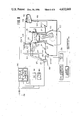
- FIG. 7 is a schematic partially sectioned view showing a "vapor" cooled type engine system equipped with a first embodiment of the present invention
- FIG. 8 is a view similar to that shown in FIG. 7 showing a second embodiment of the present invention.
- FIG. 9 is a timing chart showing the operation of the monitoring circuit which characterizes the first embodiment
- FIG. 10 is a chart showing the correspondence between the pump operation and the change in coolant level within the coolant jacket of the engine system to which the embodiments of the present invention are applied;
- FIG. 11 is a chart comparing the pump operation characteristics which occur at high and low (idling) load conditions, respectively.
- FIG. 12 is a chart which shows the continuous ON and the continuous OFF pump characteristics which occur when a system malfuction takes place.
- FIG. 5 graphically shows, in terms of engine torque and engine speed, the various load "zones" which are encountered by an automotive vehicle engine.
- the curve F denotes full throttle torque characteristics
- trace L denotes the resistance encountered when a vehicle is running on a level surface
- zones I, II and III denote respectively what shall be referred to as “urban cruising”, “high speed cruising” and “high load operation” (such as hillclimbing, towing etc.).
- a suitable coolant temperature for zone I is in the order of 120° C. (for example) while as low as 90° C. (for example) for zones II and III. If desired it is possible to induce the coolant to boil at approximately 100° C. in zone II if so desired.
- the high temperature during "urban cruising” promotes improved thermal efficiency and fuel economy while the lower temperatures promote improved charging efficiency while simultaneously removing sufficient heat from the engine and associated structure to obviate engine knocking and/or possibility of engine damage in the other zones.
- FIG. 7 shows an engine system incorporating a first embodiment of the present invention.
- an internal combustion engine 100 includes a cylinder block 106 on which a cylinder head 104 is detachably secured.
- the cylinder head 104 and cylinder block 106 include suitable cavities which define a coolant jacket 120 about the heated portions of the cylinder head and block.
- radiator or heat exchanger 126 Fluidly communicating with a vapor discharge port of the cylinder head 104 via a vapor manifold 122 and vapor transfer conduit 123, is a radiator or heat exchanger 126. It should be noted that the interior of this radiator 126 is maintained essentially empty of liquid coolant during normal engine operation so as to maximize the surface area available for condensing coolant vapor (via heat exchange with the ambient atmosphere) and that the cooling system as a whole (viz., the cooling circuit encompassed by the coolant jacket, radiator and conduiting interconnecting same) is hermetically closed when the engine is warmed-up and running.
- a mesh screen or like separator (not shown) can be disposed in the vapor discharge port 121 of the cylinder head so as to minimize the transfer of liquid coolant which tends to froth during boiling, to the radiator 126.
- cylinder head/manifold arrangements such as disclosed in U.S. Pat. No. 4,499,866 issued on Feb. 19, 1985 in the name of Hirano and U.S. patent application Ser. No. 642,369 filed June 25, 1984 in the name of Hirano et al, can be employed if desired.
- a electrically driven fan 127 Located suitably adjacent the radiator 126 is a electrically driven fan 127.
- a small collection reservoir or lower tank 128 as it will be referred to hereinafter.
- a level sensor 130 Disposed in the lower tank 128 is a level sensor 130 which is adapted to output a signal indicative of the level of liquid coolant in the lower tank 128 falling therebelow. Viz., being lower than a level which is beneath the lower ends of the relatively small diameter tubing which constitute heat exchanging portion the radiator.
- a return conduit 132 Leading from the lower tank 128 to the cylinder block 120 is a return conduit 132. As shown, a "three-way" type electromagnetic valve 134 and a relatively small capacity return pump 136 are disposed in this conduit. The valve 134 is located upstream of the pump 136. The return conduit 132 is arranged to communicate with the lowermost portion of the coolant jacket 120.
- a level sensor 140 is disposed as shown. It will be noted that this sensor is arranged at a level higher than that of the combustion chambers, exhaust ports and valves (i.e. structure subject to high heat flux) so as to enable same to be securely immersed in coolant and thus attenuate any engine knocking and the like which might otherwise occur due to the formation of localized zones of abnormally high temperature or "hot spots”. It will also be noted that the level sensor 140 is located at a level lower than the upper section or roof of the structure of the cylinder head which defines the coolant jacket therein, so as to define a coolant vapor collection space above the liquid coolant.
- a temperature sensor 144 Located below the level sensor 140 so as to be immersed in the liquid coolant is a temperature sensor 144.
- a coolant reservoir 146 is located beside the engine proper as shown.
- An air permeable cap 148 is used to close the reservoir 146 in a manner that atmospheric pressure continuously prevails therein.
- the reservoir 146 fluidly communicates with the "three-way" valve 134 via a supply conduit 149 and with the engine coolant jacket 120 via a fill/discharge conduit 150 and an ON/OFF type electromagnetic valve 152.
- the three-way valve 134 is arranged to establish fluid communication between the lower tank 128 and the coolant jacket 120 when de-energized while establish fluid communication between the coolant jacket 120 and the reservoir 146 when energized.
- Valve 152 is arranged to be closed when energized.
- the vapor manifold 122 is formed with a "purge" port 166 and a riser like portion 167 which is hermetically closed by a cap 168.
- the purge port 166 communicates with the reservoir 164 via a overflow conduit 169.
- a normally closed electromagnetic valve 170 is disposed in the overflow conduit 169. This valve is arranged to be open only when energized.
- the above mentioned level sensors 130 & 140 may be of any suitable type such as float/reed switch types.
- control circuit 180 includes therein a microprocessor including input and output interfaces I/O a CPU, a RAM and a ROM. Suitable control programs are set in the ROM and are used to control the operation of the valves 134, 152 & 170, pump 136 and fan 127 in response to the various data supplied thereto.
- a load sensor 182 and an engine speed sensor 184 are arranged to supply data signals to control circuit 180.
- the load sensor may take the form of a throttle position switch which is tiggered upon the engine throttle valve being opened beyond a predetermined degree. Alternatively the output of an air flow meter or an induction vacuum sensor may be used.
- the engine speed signal may be derived from the engine distributor, a crankshaft rotational speed sensor or the like.
- the cooling system Prior to initial use the cooling system (including the heat exchanger housing passages 804) is completely filled with coolant (for example water or a mixture of water and antifreeze or the like) and the cap 168 securely set in place to seal the system. A suitable quantity of additional coolant is also introduced into the reservoir 146.
- coolant for example water or a mixture of water and antifreeze or the like
- a suitable quantity of additional coolant is also introduced into the reservoir 146.
- a non-condensible matter purge operation is carried out upon start-up of the engine, given that the engine temperature is below a predetermined value (45° C. for example) a non-condensible matter purge operation is carried out.
- the purge operation is effected by pumping excess coolant into the system for a predetermined period of time. As the system should be essentially full before the initiation of this operation, the excess coolant thus introduced, positively displaces any air or the like the might have collected.
- the purge operation is carried out by energizing valves 152, 134 and 170 and energizing the pump for several tens of seconds.
- valve 152 is conditioned to assume a closed condition, valve 170 an open one and valve 136 conditioned to establish communication between the reservoir 146 and the coolant jacket 120.
- pump inducts coolant from the reservoir 146 via conduit 149 and forces same into the coolant jacket through conduit 132.
- the excess coolant thus introduced accordingly escapes from the top of the system via overflow conduit 169 and is returned to the reservoir. Any air or like non-condensible matter is carried out of the system along with the overflowing coolant.
- valve 152 is energized to assume an open state while valves 170 and 134 are deenergized to respectively assume a closed position and one in which the coolant jacket 120 is placed in fluid communication with the reservoir 146.
- pump 136 is energized and coolant is pumped from the radiator 126 into the coolant jacket so as to maintain the level of coolant therein at that of level sensor 140. Accordingly, as coolant is simultaneously being displaced from the system via conduit 150, the radiator and second vapor conduit are emptied of coolant until the situation show in FIG. 1 occurs.
- level sensor 140 is arranged to output a signal indicative of the coolant having fallen below a first predetermined level and maintain said output until the coolant has risen to a second level which is higher than the first. This hysteresis action of course obviates rapid ON/OFF cycling of the pump.
- the system immediately undergoes a "warm start" wherein the purge operation is by-passed and the coolant displaced mode directly entered.
- coolant would not be recirculated from the collection tank 128 to the coolant jacket 120. Accordingly, the coolant in the coolant jacket 120 would be gradually boiled off leading to (a) too much coolant in the radiator (viz. the radiator would become partially flooded and the surface area via which latent heat of vaporization which can be released to the ambient atmosphere, reduced) and (b) too little in the coolant jacket. Accordingly, as the cylinder head would not be immersed in sufficient coolant to remove the heat emitted therefrom the engine would undergo rapid overheating and thermal damage;
- a first embodiment of a malfunction detection circuit 200 according to the present invention is incorporated with the engine system shown in FIG. 7.
- This arrangement includes a differential circuit 210 which is connected to the "live" terminal of the pump 136 so as to be responsive to the energization signals fed thereto.
- a circuit 214 Connected in series between the differential circuit 210 and a comparator 212 is a circuit 214 which detects the period for which the pump 136 operates and is non-operative.
- a driver or amplifier circuit 216 Following the comparator 212 is a driver or amplifier circuit 216 which upon receiving an output from the comparator generates a suitable voltage signal via which an alarm indicator 218--such as a lamp or buzzer (or alternatively a voice warning system) is energized.
- FIG. 9 shows in timing chart form, the signals which characterize the operation of the above disclosed circuit.
- the left-hand section of this chart shows normal or malfunction free operation while the right-hand side section shows the operation which occurs in the event of a malfunction.
- the differential circuit 210 produces a pulse (see chart “A") each time the pump 136 is started or stopped.
- the period responsive circuit 214 responds to each of the pulses in a manner to be “reset” by same and thereafter develop a voltage which develops essentially proportionally with respect to time (see chart “B”). Accordingly, the greater the lapse of time between any two pulses the higher the voltage becomes.
- REF V reference voltage
- FIG. 8 shows a second embodiment of the present invention.
- This arrangement takes into account the changes in pump operation characteristics which occur with changes in engine load. Viz., under high load the amount of power that must be produced by the engine is high and accordingly a relatively large amount of fuel is combusted to produce the necessary power output. The more fuel that is combusted, the more heat that is produced by the engine. Under these circumstances the amount of coolant that must be circulated by the pump increases whereby the time for which the pump operates increases while the time for which it is non-operative decreases.
- FIG. 11 demonstrates this point graphically. As shown, during idling the time for which the pump is active is relatively short while the intervals between pump energization relatively large.
- the pump is required to pump more coolant more often. Accordingly, in order to render the monitoring circuit more responsive to the mode of engine operation it is preferred in the second embodiment to render said circuit responsive to a signal indicative of the amount of fuel being fed to the engine.
- the fuel injector control pulse can be used.
- the opening degree of the throttle valve may be used.
- the second embodiment includes a timer 310 circuit which determines the time or period for which the pump is active/non-active. In response to a signal indicative of low fuel consumption it is possible to render the timer 310 responsive to the pump 136 being "on” so as to count up to a level at which a warning device (312) energization signal is produced faster than in the case that the pump 136 is not energized. Conversely, when the amount of fuel fed to the engine increases (high load) it is possible by using the signal indicative thereof to increase the rate at which the counter 310 counts up to a value at which the alarm signal is issued or conversely lower the count at which said signal is generated.
Landscapes
- Engineering & Computer Science (AREA)
- Chemical & Material Sciences (AREA)
- Combustion & Propulsion (AREA)
- Mechanical Engineering (AREA)
- General Engineering & Computer Science (AREA)
- Combined Controls Of Internal Combustion Engines (AREA)
- Testing Of Engines (AREA)
Applications Claiming Priority (2)
| Application Number | Priority Date | Filing Date | Title |
|---|---|---|---|
| JP59-38280 | 1984-02-29 | ||
| JP59038280A JPS60182310A (ja) | 1984-02-29 | 1984-02-29 | 沸騰冷却エンジンの異常警報装置 |
Publications (1)
| Publication Number | Publication Date |
|---|---|
| US4632069A true US4632069A (en) | 1986-12-30 |
Family
ID=12520900
Family Applications (1)
| Application Number | Title | Priority Date | Filing Date |
|---|---|---|---|
| US06/705,928 Expired - Fee Related US4632069A (en) | 1984-02-29 | 1985-02-26 | Cooling system for automotive engine |
Country Status (2)
| Country | Link |
|---|---|
| US (1) | US4632069A (enExample) |
| JP (1) | JPS60182310A (enExample) |
Cited By (6)
| Publication number | Priority date | Publication date | Assignee | Title |
|---|---|---|---|---|
| US4722304A (en) * | 1986-01-10 | 1988-02-02 | Nissan Motor Co., Ltd. | Cooling system for automotive engine or the like |
| US4960083A (en) * | 1988-10-11 | 1990-10-02 | Honda Giken Kogyo Kabushiki Kaisha | Failsafe method in connection with valve timing-changeover control for internal combustion engines |
| US5582138A (en) * | 1995-03-17 | 1996-12-10 | Standard-Thomson Corporation | Electronically controlled engine cooling apparatus |
| KR100444682B1 (ko) * | 2002-06-14 | 2004-08-21 | 현대자동차주식회사 | 자동차용 워터펌프의 이상유무 감지장치 및 그 제어방법 |
| US20080148829A1 (en) * | 2006-12-06 | 2008-06-26 | Carl Bohman | Method and device for operating a drive unit |
| US20250172088A1 (en) * | 2022-05-17 | 2025-05-29 | Volvo Truck Corporation | Active coolant monitoring and leak mitigation in vehicle cooling systems |
Citations (5)
| Publication number | Priority date | Publication date | Assignee | Title |
|---|---|---|---|---|
| US1687679A (en) * | 1922-10-30 | 1928-10-16 | Sue R Mallory | Engine-cooling system |
| US1787562A (en) * | 1929-01-10 | 1931-01-06 | Lester P Barlow | Engine-cooling system |
| US3893108A (en) * | 1973-12-20 | 1975-07-01 | Texas Instruments Inc | Internal combustion engine protection circuit |
| US4367699A (en) * | 1981-01-27 | 1983-01-11 | Evc Associates Limited Partnership | Boiling liquid engine cooling system |
| JPS58144622A (ja) * | 1982-02-24 | 1983-08-29 | Nippon Denso Co Ltd | 車両用内燃機関冷却系統のための冷却水温表示装置 |
-
1984
- 1984-02-29 JP JP59038280A patent/JPS60182310A/ja active Granted
-
1985
- 1985-02-26 US US06/705,928 patent/US4632069A/en not_active Expired - Fee Related
Patent Citations (5)
| Publication number | Priority date | Publication date | Assignee | Title |
|---|---|---|---|---|
| US1687679A (en) * | 1922-10-30 | 1928-10-16 | Sue R Mallory | Engine-cooling system |
| US1787562A (en) * | 1929-01-10 | 1931-01-06 | Lester P Barlow | Engine-cooling system |
| US3893108A (en) * | 1973-12-20 | 1975-07-01 | Texas Instruments Inc | Internal combustion engine protection circuit |
| US4367699A (en) * | 1981-01-27 | 1983-01-11 | Evc Associates Limited Partnership | Boiling liquid engine cooling system |
| JPS58144622A (ja) * | 1982-02-24 | 1983-08-29 | Nippon Denso Co Ltd | 車両用内燃機関冷却系統のための冷却水温表示装置 |
Cited By (6)
| Publication number | Priority date | Publication date | Assignee | Title |
|---|---|---|---|---|
| US4722304A (en) * | 1986-01-10 | 1988-02-02 | Nissan Motor Co., Ltd. | Cooling system for automotive engine or the like |
| US4960083A (en) * | 1988-10-11 | 1990-10-02 | Honda Giken Kogyo Kabushiki Kaisha | Failsafe method in connection with valve timing-changeover control for internal combustion engines |
| US5582138A (en) * | 1995-03-17 | 1996-12-10 | Standard-Thomson Corporation | Electronically controlled engine cooling apparatus |
| KR100444682B1 (ko) * | 2002-06-14 | 2004-08-21 | 현대자동차주식회사 | 자동차용 워터펌프의 이상유무 감지장치 및 그 제어방법 |
| US20080148829A1 (en) * | 2006-12-06 | 2008-06-26 | Carl Bohman | Method and device for operating a drive unit |
| US20250172088A1 (en) * | 2022-05-17 | 2025-05-29 | Volvo Truck Corporation | Active coolant monitoring and leak mitigation in vehicle cooling systems |
Also Published As
| Publication number | Publication date |
|---|---|
| JPH039286B2 (enExample) | 1991-02-08 |
| JPS60182310A (ja) | 1985-09-17 |
Similar Documents
| Publication | Publication Date | Title |
|---|---|---|
| US4549505A (en) | Cooling system for automotive engine or the like | |
| US4563983A (en) | Intercooler arrangement for supercharged internal combustion engine | |
| EP0126422B1 (en) | Improved cooling system for automotive engine or the like | |
| US4788943A (en) | Cooling system for automotive engine or the like | |
| EP0207354B1 (en) | Method and system for cooling automotive engines | |
| US4648357A (en) | Cooling system for automotive engine or the like | |
| US4782795A (en) | Anti-knock system for automotive internal combustion engine | |
| EP0161687B1 (en) | Cooling system for automotive engine | |
| US4658766A (en) | Cooling system for automotive engine or the like | |
| US4648356A (en) | Evaporative cooling system of internal combustion engine | |
| US4649869A (en) | Cooling system for automotive engine or the like | |
| US4677942A (en) | Cooling system for automotive engine or the like | |
| US4694784A (en) | Cooling system for automotive engine or the like | |
| US4622925A (en) | Cooling system for automotive engine or the like | |
| US4628872A (en) | Cooling system for automotive engine or the like including coolant return pump back-up arrangement | |
| EP0146057B1 (en) | Cooling system for automotive engine | |
| US4630573A (en) | Cooling system for automotive engine or the like | |
| US4632069A (en) | Cooling system for automotive engine | |
| US4605164A (en) | Cabin heating arrangement for vehicle having evaporative cooled engine | |
| EP0167169B1 (en) | Cooling system for automotive engine or the like | |
| US4577594A (en) | Cooling system for automotive engine | |
| US4662318A (en) | Cooling system for automotive internal combustion engine or the like | |
| EP0135116B1 (en) | Cooling system for automotive engine or the like | |
| US4624221A (en) | Cooling system for automotive engine or the like | |
| US4686942A (en) | Cooling system for automotive engine or the like |
Legal Events
| Date | Code | Title | Description |
|---|---|---|---|
| AS | Assignment |
Owner name: NISSAN MOTOR CO., LTD NO 2, AKARA-CHO KANAGAWA-KU Free format text: ASSIGNMENT OF ASSIGNORS INTEREST.;ASSIGNORS:AOKI, HIROFUMI;HAYASHI, YOSHIMASA;REEL/FRAME:004375/0948 Effective date: 19850110 |
|
| FEPP | Fee payment procedure |
Free format text: PAYOR NUMBER ASSIGNED (ORIGINAL EVENT CODE: ASPN); ENTITY STATUS OF PATENT OWNER: LARGE ENTITY |
|
| FPAY | Fee payment |
Year of fee payment: 4 |
|
| FEPP | Fee payment procedure |
Free format text: PAYER NUMBER DE-ASSIGNED (ORIGINAL EVENT CODE: RMPN); ENTITY STATUS OF PATENT OWNER: LARGE ENTITY Free format text: PAYOR NUMBER ASSIGNED (ORIGINAL EVENT CODE: ASPN); ENTITY STATUS OF PATENT OWNER: LARGE ENTITY |
|
| FPAY | Fee payment |
Year of fee payment: 8 |
|
| REMI | Maintenance fee reminder mailed | ||
| LAPS | Lapse for failure to pay maintenance fees | ||
| FP | Lapsed due to failure to pay maintenance fee |
Effective date: 19981230 |
|
| STCH | Information on status: patent discontinuation |
Free format text: PATENT EXPIRED DUE TO NONPAYMENT OF MAINTENANCE FEES UNDER 37 CFR 1.362 |