US4630745A - Foldable containers - Google Patents
Foldable containers Download PDFInfo
- Publication number
- US4630745A US4630745A US06/711,412 US71141285A US4630745A US 4630745 A US4630745 A US 4630745A US 71141285 A US71141285 A US 71141285A US 4630745 A US4630745 A US 4630745A
- Authority
- US
- United States
- Prior art keywords
- frame
- bottom plate
- plate
- plates
- pair
- Prior art date
- Legal status (The legal status is an assumption and is not a legal conclusion. Google has not performed a legal analysis and makes no representation as to the accuracy of the status listed.)
- Expired - Lifetime
Links
Images


Classifications
-
- B—PERFORMING OPERATIONS; TRANSPORTING
- B65—CONVEYING; PACKING; STORING; HANDLING THIN OR FILAMENTARY MATERIAL
- B65D—CONTAINERS FOR STORAGE OR TRANSPORT OF ARTICLES OR MATERIALS, e.g. BAGS, BARRELS, BOTTLES, BOXES, CANS, CARTONS, CRATES, DRUMS, JARS, TANKS, HOPPERS, FORWARDING CONTAINERS; ACCESSORIES, CLOSURES, OR FITTINGS THEREFOR; PACKAGING ELEMENTS; PACKAGES
- B65D11/00—Containers having bodies formed by interconnecting or uniting two or more rigid, or substantially rigid, components made wholly or mainly of plastics material
- B65D11/18—Containers having bodies formed by interconnecting or uniting two or more rigid, or substantially rigid, components made wholly or mainly of plastics material collapsible, i.e. with walls hinged together or detachably connected
- B65D11/182—Containers having bodies formed by interconnecting or uniting two or more rigid, or substantially rigid, components made wholly or mainly of plastics material collapsible, i.e. with walls hinged together or detachably connected comprising two side walls hinged along the sides of a base panel and to an upper frame and two other side walls being hinged only to the upper frame
Definitions
- This invention relates to a foldable container utilized for transporting various goods.
- a prior art foldable container disclosed in Japanese Laid-open Utility Model Nos. 36350/1980 and 4596/1981 comprises a frame, a bottom plate, foldable side plates rotatably connected to both the frame and bottom plate and end plates rotatably supported by the frame.
- two folded side plates are brought to vertically straight positions, and the end plates are rotated toward the bottom plate so as to cause the lower ends of the end plates to engage with the bottom plate.
- the engagement between the lower ends of the end plates and the bottom plate is released, the end plates are rotated inwardly and the side plates are folded thereby integrating the frame and the bottom plate.
- the folding plates are complicated and require a number of component parts, thus increasing cost and reducing productivity.
- the side plates are folded, their thickness increases so that the thickness of the folded container increases, whereby, when a number of folded containers are piled up, the height of the pile increases.
- Another object of this invention is to provide an improved foldable container capable of reducing the height thereof, thereby increasing the efficiency of piling up.
- a further object of this invention is to provide an improved foldable container capable of reducing the weight thereof.
- a foldable container comprising
- each of said side plates being rotatably connected to said frame while the lower end thereof being detachably engagable with said bottom plate;
- each of said end plates being detachably engagable with said frame while the lower end thereof being detachably engagable with said studs of said bottom plate.
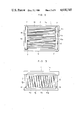
- FIG. 1 is a perspective view showing one example of a foldable container embodying the invention
- FIG. 2 is a plan view thereof
- FIG. 3 is a front view thereof
- FIG. 4 is an enlarged sectional view taken along a line IV--IV in FIG. 1;
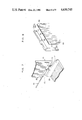
- FIG. 5 is an exploded perspective view showing the relation of a frame and an end plate
- FIG. 6 is an enlarged sectional view taken along a line VI--VI in FIG. 1;
- FIG. 7 is an exploded perspective view showing the relation of an end plate and a bottom plate
- FIG. 8 is an exploded perspective view showing the relation of a frame part and a flat part of a side plate
- FIG. 9 is a perspective view showing the state of assembling or folding of the container.
- FIG. 10 is a perspective view showing a folded container
- FIG. 11 is an enlarged sectional view taken along a line XI--XI in FIG. 10, and
- FIG. 12 is an enlarged sectional view taken along a line XII--XII in FIG. 10.
- a foldable container embodying the invention comprises a rectangular upper frame 1, a pair of side plates 5 ⁇ 5, a pair of end plates 13 ⁇ 13, and a bottom plate 10, all of which are made of synthetic resins such as polypropylene resin or ABS resin.
- the frame 1 has an inverted U-shaped cross-section and is provided with a pair of flanges 2 ⁇ 2 horizontally projected at the insides of the longer sides 1a ⁇ 1a thereof.
- a plurality of bosses 3 are integrally provided at suitable intervals in the longitudinal direction of the flange 2.
- the frame 1 is also provided with upwardly bent edges 8, as shown in FIG. 6, at the insides of the shorter sides 1b ⁇ 1b thereof.
- Each end plate 13 is provided with a downwardly bent edge 15, as shown in FIG. 6, at the upper side thereof to be engagable with the bent edge 8 of the frame 1 so that each end plate 13 is detachably connected to the shorter side 1b of the frame 1.
- Each end plate 13 is also provided with suitably spaced bosses 131, as shown in FIG. 7, at the lower side thereof.
- Each side plate 5 is provided at the upper side thereof, as illustrated in FIGS. 5 and 6, with a plurality of pairs of bosses 51a ⁇ 51b corresponding to the bosses 3 of the frame 1, and each pair of bosses 51a ⁇ 51b are pivoted to the corresponding boss 3 by a pivot shaft 6 so that each side plate 5 is rotatably and detachably connected to the longer side 1a of the frame 1.
- Each side plate 5 is also provided with a plurality of openings 9, as illustrated in FIGS. 4 and 6, at the lower side thereof.
- the bottom plate 10 is provided with studs 12, as illustrated in FIGS. 6 and 7, at the shorter sides 10b ⁇ 10b thereof.
- the height and width of each stud 12 are determined such that the stud 12 can fit in the spacing 7 between the end of flange 2 and the edge 8 as illustrated in FIG. 12.
- Each stud 12 is integrally formed with suitably spaced bosses 16 to be fit into the spacing between the adjacent pair of bosses 131 of the end plate 13 and rotatably connected therewith by a supporting shaft 14.
- the bottom plate 10 is also provided with a plurality of inwardly bent hooks 11, as shown in FIGS. 4 and 6, at each longer side 10a thereof to be inserted into the openings 9 of the side plate 5 so that each side plate 5 is detachably connected to the bottom plate 10.
- Each of side plates 5, bottom plate 10 and end plates 13 is comprised of a frame part 5a,10a,13a and a partitioned hollow flat part 5b,10b,13b.
- the frame part 5a is, for example, provided with a plurality of pins 20 along the inner periphery thereof while a plurality of corresponding holes 22 are formed on the flat part 5b.
- the pins 20 of the frame part 5a are inserted through the holes 22 of the flat part 5a and the front ends of the pins 20 protruding from the holes 22 are deformed to tightly hook the flat part 5b onto the frame part 5a by heat pressing.
- the flat parts 10b ⁇ 13b of the bottom plate 10 and end plates 13 are hooked to the frame parts 10a ⁇ 13a thereof in the same manner.
- the frame parts 5a ⁇ 10a ⁇ 13a, the flat parts 5b ⁇ 10b ⁇ 13b and the shafts 6 ⁇ 14 are formed by the same synthetic resin such as polypropylene resin or ABS resin, which contributes to retreatment of resin when containers are exploded.
- the upper sides of the end plates 13 are rotated to the vertical direction. Then, while engaging the end plates 13 with the spacings 7, the upper frame 1 is raised upwardly to cause the edges 15 of the end plates 13 to engage with edges 8. At this state, after rotating the lower sides of the side plates 5 outwardly, hooks 11 of the bottom plate 10 are fitted into the openings 9 of the side plates 5. At this stage, the upper frame 1 and the bottom plate 10 are maintained spaced apart, and since the end surfaces of the side plates 5 contact the inner surfaces of both ends of the end plate 13, the container is maintained a box shape.
Abstract
A foldable container includes an upper rectangular frame; a rectangular bottom plate having studs insertable into opposing sides of said upper frame; a pair of side plates, the upper end of each side plate being rotatably connected to said frame while the lower end is detachably engagable with said bottom plate; and a pair of end plates, the upper end of each end plate being detachably engagable with said frame while the lower end is detachably engageable with the studs of the bottom plate.
Description
This invention relates to a foldable container utilized for transporting various goods.
A prior art foldable container disclosed in Japanese Laid-open Utility Model Nos. 36350/1980 and 4596/1981 comprises a frame, a bottom plate, foldable side plates rotatably connected to both the frame and bottom plate and end plates rotatably supported by the frame. At the time of assembling, while maintaining the frame and the bottom plate separated away, two folded side plates are brought to vertically straight positions, and the end plates are rotated toward the bottom plate so as to cause the lower ends of the end plates to engage with the bottom plate. When folding such a container, the engagement between the lower ends of the end plates and the bottom plate is released, the end plates are rotated inwardly and the side plates are folded thereby integrating the frame and the bottom plate.
However, in the foldable container of the type described above, since the side plates which are supported to be rotatable or foldable with respect to the frame and the bottom plate are foldably prepared, the folding plates are complicated and require a number of component parts, thus increasing cost and reducing productivity. Moreover, as the side plates are folded, their thickness increases so that the thickness of the folded container increases, whereby, when a number of folded containers are piled up, the height of the pile increases.
Accordingly, it is an object of this invention to provide an improved foldable container that can readily be assembled and folded, and can be manufactured at a low cost and high productivity.
Another object of this invention is to provide an improved foldable container capable of reducing the height thereof, thereby increasing the efficiency of piling up.
A further object of this invention is to provide an improved foldable container capable of reducing the weight thereof.
According to this invention, there is provided a foldable container comprising
an upper rectangular frame;
a rectangular bottom plate having studs insertable into opposing sides of said upper frame;
a pair of side plates, the upper end of each of said side plates being rotatably connected to said frame while the lower end thereof being detachably engagable with said bottom plate; and
a pair of end plates, the upper end of each of said end plates being detachably engagable with said frame while the lower end thereof being detachably engagable with said studs of said bottom plate.
FIG. 1 is a perspective view showing one example of a foldable container embodying the invention;
FIG. 2 is a plan view thereof;
FIG. 3 is a front view thereof;
FIG. 4 is an enlarged sectional view taken along a line IV--IV in FIG. 1;
FIG. 5 is an exploded perspective view showing the relation of a frame and an end plate;
FIG. 6 is an enlarged sectional view taken along a line VI--VI in FIG. 1;
FIG. 7 is an exploded perspective view showing the relation of an end plate and a bottom plate;
FIG. 8 is an exploded perspective view showing the relation of a frame part and a flat part of a side plate;
FIG. 9 is a perspective view showing the state of assembling or folding of the container;
FIG. 10 is a perspective view showing a folded container;
FIG. 11 is an enlarged sectional view taken along a line XI--XI in FIG. 10, and
FIG. 12 is an enlarged sectional view taken along a line XII--XII in FIG. 10.
As shown in FIGS. 1 through 3, a foldable container embodying the invention comprises a rectangular upper frame 1, a pair of side plates 5·5, a pair of end plates 13·13, and a bottom plate 10, all of which are made of synthetic resins such as polypropylene resin or ABS resin.
The frame 1 has an inverted U-shaped cross-section and is provided with a pair of flanges 2·2 horizontally projected at the insides of the longer sides 1a·1a thereof. At the lower side of each flange 2, as illustrated in FIGS. 5 and 6, a plurality of bosses 3 are integrally provided at suitable intervals in the longitudinal direction of the flange 2. The frame 1 is also provided with upwardly bent edges 8, as shown in FIG. 6, at the insides of the shorter sides 1b·1b thereof.
Each end plate 13 is provided with a downwardly bent edge 15, as shown in FIG. 6, at the upper side thereof to be engagable with the bent edge 8 of the frame 1 so that each end plate 13 is detachably connected to the shorter side 1b of the frame 1. Each end plate 13 is also provided with suitably spaced bosses 131, as shown in FIG. 7, at the lower side thereof.
Each side plate 5 is provided at the upper side thereof, as illustrated in FIGS. 5 and 6, with a plurality of pairs of bosses 51a·51b corresponding to the bosses 3 of the frame 1, and each pair of bosses 51a·51b are pivoted to the corresponding boss 3 by a pivot shaft 6 so that each side plate 5 is rotatably and detachably connected to the longer side 1a of the frame 1. Each side plate 5 is also provided with a plurality of openings 9, as illustrated in FIGS. 4 and 6, at the lower side thereof.
The bottom plate 10 is provided with studs 12, as illustrated in FIGS. 6 and 7, at the shorter sides 10b·10b thereof. The height and width of each stud 12 are determined such that the stud 12 can fit in the spacing 7 between the end of flange 2 and the edge 8 as illustrated in FIG. 12. Each stud 12 is integrally formed with suitably spaced bosses 16 to be fit into the spacing between the adjacent pair of bosses 131 of the end plate 13 and rotatably connected therewith by a supporting shaft 14.
The bottom plate 10 is also provided with a plurality of inwardly bent hooks 11, as shown in FIGS. 4 and 6, at each longer side 10a thereof to be inserted into the openings 9 of the side plate 5 so that each side plate 5 is detachably connected to the bottom plate 10.
Each of side plates 5, bottom plate 10 and end plates 13 is comprised of a frame part 5a,10a,13a and a partitioned hollow flat part 5b,10b,13b. As illustrated in FIG. 8, the frame part 5a is, for example, provided with a plurality of pins 20 along the inner periphery thereof while a plurality of corresponding holes 22 are formed on the flat part 5b. The pins 20 of the frame part 5a are inserted through the holes 22 of the flat part 5a and the front ends of the pins 20 protruding from the holes 22 are deformed to tightly hook the flat part 5b onto the frame part 5a by heat pressing. The flat parts 10b·13b of the bottom plate 10 and end plates 13 are hooked to the frame parts 10a·13a thereof in the same manner.
The frame parts 5a·10a·13a, the flat parts 5b·10b·13b and the shafts 6·14 are formed by the same synthetic resin such as polypropylene resin or ABS resin, which contributes to retreatment of resin when containers are exploded.
The ways of assembling and folding the container will now be described with reference to FIGS. 9 through 12.
First, to fold the container illustrated in FIG. 1, hooks 11 of the bottom plate 10 are disengaged from the openings 9 of the side plates 5, and then the lower sides of the side plates 5 are rotated inwardly to be leveled beneath the flanges 2 of the upper frame 1. Thereafter, after disengaging edges 15 of the end plates 13 from the edges 8 of the frame 1, the upper frame 1 is moved down toward the bottom plate 10 while maintaining each side plate 5 to be positioned in the spacing 7 between the end of flange 2 and the edge 8 of the frame 1. Then, after fitting studs 12 into the spacings 7, the upper sides of the end plates 13 are rotated inwardly for overlapping the end plates 13 above the flanges 2 of the upper frame 1. Thus, the container is folded as illustrated in FIG. 10.
On the contrary, to assemble the container illustrated in FIG. 10, the upper sides of the end plates 13 are rotated to the vertical direction. Then, while engaging the end plates 13 with the spacings 7, the upper frame 1 is raised upwardly to cause the edges 15 of the end plates 13 to engage with edges 8. At this state, after rotating the lower sides of the side plates 5 outwardly, hooks 11 of the bottom plate 10 are fitted into the openings 9 of the side plates 5. At this stage, the upper frame 1 and the bottom plate 10 are maintained spaced apart, and since the end surfaces of the side plates 5 contact the inner surfaces of both ends of the end plate 13, the container is maintained a box shape.
Claims (5)
1. A foldable container, comprising:
an upper rectangular frame wherein said frame is provided with a pair of flanges on one pair of opposed inner sides and upwardly bent edges on the remaining pair of opposed inner sides;
a rectangular bottom plate having studs insertable into opposing sides of said upper frame;
a pair of side plates, the upper end of each of said side plates being rotatably connected to a corresponding flange of said upper frame, and the lower end of each side plate being detachably engageable with said bottom plate;
wherein each side plate is provided with a plurality of openings at the lower side thereof, and said bottom plate is provided with a plurality of inwardly protruded bosses to be inserted through said openings of each side plate; and
a pair of end plates, the upper end of each of said end plates being detachably engageable with said frame and the lower end of each end plate being detachably engageable with said studs of said bottom plate;
wherein each side of said end plate is fit into a spacing between side edges of said flanges and an adjacent inner side surface of said frame, and each end plate is provided with a downwardly bent edge at the upper end thereof to be engageable with said bent edge of the frame.
2. The foldable container according to claim 1 wherein at least one of said side plates, end plates and bottom plate is comprised of a frame part and a flat part arranged to be hooked to the frame part by heat pressing.
3. The foldable container according to claim 2 wherein said frame part is provided with a plurality of pins protruded inwardly, and said flat part is provided with a plurality of holes to receive said pins of the frame part.
4. The foldable container according to claim 2 wherein said flat part comprises a partitioned hollow member.
5. The foldable container according to claim 2 wherein said frame part and said flat part are formed by the same synthetic resin.
Applications Claiming Priority (5)
| Application Number | Priority Date | Filing Date | Title |
|---|---|---|---|
| JP5533784U JPS60167733U (en) | 1984-04-13 | 1984-04-13 | folding container |
| JP59-55337[U] | 1984-04-13 | ||
| JP59-135293[U]JPX | 1984-09-05 | ||
| JP13529384U JPS6148125U (en) | 1984-09-05 | 1984-09-05 | folding container |
| JP17796484U JPH0138027Y2 (en) | 1984-11-22 | 1984-11-22 |
Publications (1)
| Publication Number | Publication Date |
|---|---|
| US4630745A true US4630745A (en) | 1986-12-23 |
Family
ID=27295571
Family Applications (1)
| Application Number | Title | Priority Date | Filing Date |
|---|---|---|---|
| US06/711,412 Expired - Lifetime US4630745A (en) | 1984-04-13 | 1985-03-13 | Foldable containers |
Country Status (2)
| Country | Link |
|---|---|
| US (1) | US4630745A (en) |
| DE (2) | DE3510541A1 (en) |
Cited By (16)
| Publication number | Priority date | Publication date | Assignee | Title |
|---|---|---|---|---|
| US4863056A (en) * | 1987-07-23 | 1989-09-05 | Kunimori Kagaku Co., Ltd. | Folding container |
| US5251772A (en) * | 1992-10-28 | 1993-10-12 | Yoshiaki Toguchi | Document filing case |
| US6594939B2 (en) * | 2001-12-06 | 2003-07-22 | Joseph Ondusko | Fish measuring device |
| US20040084447A1 (en) * | 2002-11-05 | 2004-05-06 | Georg Utz Holding Ag | Collapsible storage and transport container |
| US20040226945A1 (en) * | 2003-05-13 | 2004-11-18 | Hsu Roger S | Collapsible container |
| EP1637462A1 (en) * | 2004-09-17 | 2006-03-22 | Germano Maina | Folding container |
| US20080169284A1 (en) * | 2007-01-16 | 2008-07-17 | Efraim Haimoff | Storage container |
| DE102009005212A1 (en) * | 2009-01-20 | 2010-07-22 | Schoeller Arca Systems Gmbh | Container for the transport and storage of goods with a container bottom and at least two side panels hinged one above the other |
| DE202009002770U1 (en) * | 2009-02-27 | 2010-07-22 | Okt Germany Gmbh | folding |
| US8870008B2 (en) * | 2012-08-08 | 2014-10-28 | Hong Fu Jin Precision Industry (Shenzhen) Co., Ltd. | Folding box |
| US8925743B1 (en) * | 2013-08-30 | 2015-01-06 | Helen Of Troy Limited | Dish drying rack |
| CN105129189A (en) * | 2015-08-10 | 2015-12-09 | 浙江正基塑业有限公司 | Folding pass box |
| US10721910B2 (en) * | 2008-09-19 | 2020-07-28 | Carlson Pet Products, Inc. | Breakable down folding pet crate |
| WO2021173382A1 (en) * | 2020-02-25 | 2021-09-02 | Pvpallet Llc | Transport container |
| US11279514B1 (en) * | 2021-02-08 | 2022-03-22 | Protrend Co., Ltd. | Foldable basket |
| JP2022121019A (en) * | 2021-02-08 | 2022-08-19 | 盈太企業股▲ふん▼有限公司 | folding basket |
Families Citing this family (4)
| Publication number | Priority date | Publication date | Assignee | Title |
|---|---|---|---|---|
| US4630747A (en) * | 1986-04-30 | 1986-12-23 | Chiang Ming Yao | Gravitationally-operating collapsible basket |
| IT210873Z2 (en) * | 1986-05-22 | 1989-01-11 | Cosentino Giuseppe | FOLDING BOX, SUITABLE FOR THE TRANSPORT OF FRUIT AND VEGETABLES PRODUCTS IN PARTICULAR |
| DE202004014401U1 (en) * | 2004-09-15 | 2006-02-02 | Bekuplast Kunststoffverarbeitungs-Gmbh | Transport and storage container with hinged sidewalls for empty reusable packages has spring connection having spring elements whereby spring element of first sidewall has recess in cross section with spring part |
| DE202004015081U1 (en) * | 2004-09-27 | 2006-02-09 | Bekuplast Kunststoffverarbeitungs-Gmbh | Folding box with centering cams |
Citations (10)
| Publication number | Priority date | Publication date | Assignee | Title |
|---|---|---|---|---|
| US1064328A (en) * | 1912-04-30 | 1913-06-10 | Aaron A Howell | Collapsible crate. |
| US1819735A (en) * | 1929-07-11 | 1931-08-18 | Thomas E Cook | Collapsible chicken crate |
| US2755955A (en) * | 1955-08-29 | 1956-07-24 | James M Gordon | Collapsible lug box |
| US3334175A (en) * | 1964-10-28 | 1967-08-01 | Edwin B Vincent | Shielded enclosure |
| US3405835A (en) * | 1964-02-11 | 1968-10-15 | Charles M. Eby | Aluminum knock-down collapsible container |
| GB1289014A (en) * | 1970-06-12 | 1972-09-13 | ||
| US3796342A (en) * | 1972-06-05 | 1974-03-12 | Pinckney Molded Plastics | Collapsible container |
| US3870185A (en) * | 1972-06-05 | 1975-03-11 | Pinckney Molded Plastics | Collapsible container |
| US3966285A (en) * | 1974-07-17 | 1976-06-29 | Porch Don E | Collapsible shipping container |
| US4300695A (en) * | 1979-11-30 | 1981-11-17 | Hsu Te Chi | Folding container |
Family Cites Families (1)
| Publication number | Priority date | Publication date | Assignee | Title |
|---|---|---|---|---|
| DE2853558A1 (en) * | 1978-12-12 | 1980-06-19 | Walther Rolf F Dipl Ing | Collapsible container with rigid baseplate - has walls in hinging halves folding inwards in concertina pattern |
-
1985
- 1985-03-13 US US06/711,412 patent/US4630745A/en not_active Expired - Lifetime
- 1985-03-22 DE DE19853510541 patent/DE3510541A1/en active Granted
- 1985-03-22 DE DE8508684U patent/DE8508684U1/de not_active Expired - Lifetime
Patent Citations (10)
| Publication number | Priority date | Publication date | Assignee | Title |
|---|---|---|---|---|
| US1064328A (en) * | 1912-04-30 | 1913-06-10 | Aaron A Howell | Collapsible crate. |
| US1819735A (en) * | 1929-07-11 | 1931-08-18 | Thomas E Cook | Collapsible chicken crate |
| US2755955A (en) * | 1955-08-29 | 1956-07-24 | James M Gordon | Collapsible lug box |
| US3405835A (en) * | 1964-02-11 | 1968-10-15 | Charles M. Eby | Aluminum knock-down collapsible container |
| US3334175A (en) * | 1964-10-28 | 1967-08-01 | Edwin B Vincent | Shielded enclosure |
| GB1289014A (en) * | 1970-06-12 | 1972-09-13 | ||
| US3796342A (en) * | 1972-06-05 | 1974-03-12 | Pinckney Molded Plastics | Collapsible container |
| US3870185A (en) * | 1972-06-05 | 1975-03-11 | Pinckney Molded Plastics | Collapsible container |
| US3966285A (en) * | 1974-07-17 | 1976-06-29 | Porch Don E | Collapsible shipping container |
| US4300695A (en) * | 1979-11-30 | 1981-11-17 | Hsu Te Chi | Folding container |
Cited By (23)
| Publication number | Priority date | Publication date | Assignee | Title |
|---|---|---|---|---|
| US4863056A (en) * | 1987-07-23 | 1989-09-05 | Kunimori Kagaku Co., Ltd. | Folding container |
| US5251772A (en) * | 1992-10-28 | 1993-10-12 | Yoshiaki Toguchi | Document filing case |
| US6594939B2 (en) * | 2001-12-06 | 2003-07-22 | Joseph Ondusko | Fish measuring device |
| US20040084447A1 (en) * | 2002-11-05 | 2004-05-06 | Georg Utz Holding Ag | Collapsible storage and transport container |
| US7137522B2 (en) * | 2002-11-05 | 2006-11-21 | Georg Utz Holding Ag | Collapsible storage and transport container |
| US20040226945A1 (en) * | 2003-05-13 | 2004-11-18 | Hsu Roger S | Collapsible container |
| US7195127B2 (en) * | 2003-05-13 | 2007-03-27 | Rehrig Pacific Company | Collapsible container |
| EP1637462A1 (en) * | 2004-09-17 | 2006-03-22 | Germano Maina | Folding container |
| US20080169284A1 (en) * | 2007-01-16 | 2008-07-17 | Efraim Haimoff | Storage container |
| US10721910B2 (en) * | 2008-09-19 | 2020-07-28 | Carlson Pet Products, Inc. | Breakable down folding pet crate |
| US11432529B2 (en) * | 2008-09-19 | 2022-09-06 | Carlson Pet Products, Inc. | Breakable down folding pet crate |
| US11805752B2 (en) * | 2008-09-19 | 2023-11-07 | Carlson Pet Products, Inc. | Breakable down folding pet crate |
| US20220408686A1 (en) * | 2008-09-19 | 2022-12-29 | Carlson Pet Products, Inc. | Breakable down folding pet crate |
| US8567634B2 (en) | 2009-01-20 | 2013-10-29 | Schoeller Area Systems Gmbh | Foldable container for transporting and storing goods |
| DE102009005212A1 (en) * | 2009-01-20 | 2010-07-22 | Schoeller Arca Systems Gmbh | Container for the transport and storage of goods with a container bottom and at least two side panels hinged one above the other |
| DE202009002770U1 (en) * | 2009-02-27 | 2010-07-22 | Okt Germany Gmbh | folding |
| US8870008B2 (en) * | 2012-08-08 | 2014-10-28 | Hong Fu Jin Precision Industry (Shenzhen) Co., Ltd. | Folding box |
| US8925743B1 (en) * | 2013-08-30 | 2015-01-06 | Helen Of Troy Limited | Dish drying rack |
| CN105129189A (en) * | 2015-08-10 | 2015-12-09 | 浙江正基塑业有限公司 | Folding pass box |
| WO2021173382A1 (en) * | 2020-02-25 | 2021-09-02 | Pvpallet Llc | Transport container |
| US11891236B2 (en) | 2020-02-25 | 2024-02-06 | Pvpallet, Inc. | Transport container |
| JP2022121019A (en) * | 2021-02-08 | 2022-08-19 | 盈太企業股▲ふん▼有限公司 | folding basket |
| US11279514B1 (en) * | 2021-02-08 | 2022-03-22 | Protrend Co., Ltd. | Foldable basket |
Also Published As
| Publication number | Publication date |
|---|---|
| DE8508684U1 (en) | 1991-01-17 |
| DE3510541A1 (en) | 1985-10-24 |
Similar Documents
| Publication | Publication Date | Title |
|---|---|---|
| US4630745A (en) | Foldable containers | |
| US4005795A (en) | Collapsible container | |
| US3373921A (en) | Shipping container | |
| US4266714A (en) | Boxes with column-forming inserts | |
| US6619540B1 (en) | Snap lock tote box handle and tote box construction | |
| US5799812A (en) | Collapsible shipping container | |
| US3990599A (en) | Reusable shipping container | |
| US4068794A (en) | Container particularly, but not exclusively for use in shipping perishables | |
| US4863056A (en) | Folding container | |
| US4556349A (en) | Partition for a cargo carrier for bulk freight | |
| US5549242A (en) | Stackable container with reinforced corners | |
| US4270678A (en) | Bread carrier | |
| US20220033175A1 (en) | Bulk bin, bulk bin sleeve pack, and related method | |
| CA2073394C (en) | Sectional box with corner forming and locking elements | |
| US3498492A (en) | Wirebound container lid | |
| JP4147364B2 (en) | Storage box with pier | |
| JPH0138026Y2 (en) | ||
| JPH0630672Y2 (en) | Goods storage box | |
| JPH0120276Y2 (en) | ||
| JPH0547067Y2 (en) | ||
| JPH0138028Y2 (en) | ||
| GB2066775A (en) | Stackable carriers | |
| US3738562A (en) | Stacking box for transportation and storage of fruit | |
| JPS6130543Y2 (en) | ||
| JPH0138025Y2 (en) |
Legal Events
| Date | Code | Title | Description |
|---|---|---|---|
| AS | Assignment |
Owner name: KUNIMORI KAGAKU CO., LTD., 36, SHIMOSAKA-CHO, 2-CH Free format text: ASSIGNMENT OF ASSIGNORS INTEREST.;ASSIGNOR:SHIOTANI, YOSUKE;REEL/FRAME:004404/0330 Effective date: 19850430 |
|
| STCF | Information on status: patent grant |
Free format text: PATENTED CASE |
|
| FEPP | Fee payment procedure |
Free format text: PAYOR NUMBER ASSIGNED (ORIGINAL EVENT CODE: ASPN); ENTITY STATUS OF PATENT OWNER: LARGE ENTITY |
|
| FPAY | Fee payment |
Year of fee payment: 4 |
|
| FPAY | Fee payment |
Year of fee payment: 8 |
|
| FPAY | Fee payment |
Year of fee payment: 12 |