US4628828A - Ash handling systems for combustion equipment - Google Patents
Ash handling systems for combustion equipment Download PDFInfo
- Publication number
- US4628828A US4628828A US06/668,715 US66871584A US4628828A US 4628828 A US4628828 A US 4628828A US 66871584 A US66871584 A US 66871584A US 4628828 A US4628828 A US 4628828A
- Authority
- US
- United States
- Prior art keywords
- ash
- conveyor
- crusher
- hopper
- container
- Prior art date
- Legal status (The legal status is an assumption and is not a legal conclusion. Google has not performed a legal analysis and makes no representation as to the accuracy of the status listed.)
- Expired - Fee Related
Links
Images


Classifications
-
- F—MECHANICAL ENGINEERING; LIGHTING; HEATING; WEAPONS; BLASTING
- F23—COMBUSTION APPARATUS; COMBUSTION PROCESSES
- F23J—REMOVAL OR TREATMENT OF COMBUSTION PRODUCTS OR COMBUSTION RESIDUES; FLUES
- F23J1/00—Removing ash, clinker, or slag from combustion chambers
- F23J1/02—Apparatus for removing ash, clinker, or slag from ash-pits, e.g. by employing trucks or conveyors, by employing suction devices
Definitions
- This invention concerns improvements in or relating to ash handling systems for combustion equipment.
- An object of the present invention is therefore to provide an ash handling system for solid fuel combustion equipment which will facilitate ash removal and disposal in the absence of any manual involvement.
- a further object of the invention is to provide combustion equipment incorporating such an ash handling system.
- a still further object of the invention is to provide a method of operating the combustion equipment incorporating the ash handling system.
- an ash handling system including a conveyor and crusher having an inlet region adapted to receive ash from combustion equipment and an outlet region for the discharge of ash, a hopper registering with the outlet region of the conveyor and crusher, a container enclosing the hopper and defining therein an ash receiving zone, and a pneumatic extraction means associated with the ash receiving zone.
- the conveyor and crusher may advantageously be in the form of a screw provided with short robust flights and housed within a tube having an internal diameter not substantially greater than the diameter of the screw flights.
- the conveyor and crusher may be orientated horizontally or in an inclined mode.
- the outlet region of the conveyor and crusher registers with an inlet of the hopper, the inlet being located at or near the base of the hopper, the outlet of the hopper being at or near the top thereof.
- the hopper may be elevated within the container which may be provided with sloping side walls to define a trough-like configuration.
- the pneumatic extraction means may include a suction nozzle extending into the ash receiving zone from the exterior of the container, the nozzle being connected to a vacuum generating unit incorporating an ash depository.
- combustion equipment including a housing defining a combustion zone therein, a combustion means located within the combustion zone, a conveyor and crusher having an inlet region disposed beneath the combustion means and adapted to receive ash therefrom and an outlet region for the discharge of ash, a hopper registering with the outlet region of the conveyor and crusher, a container enclosing the hopper and defining therein an ash receiving zone, and a pneumatic extraction means associated with the ash receiving zone.
- the combustion means may be the retort of an underfeed stoker unit.
- the combustion means may comprise a grate.
- a method of operating the ash handling system and the combustion equipment of the first and second aspects wherein the method includes the steps of burning a solid fuel in the combustion means, allowing ash to discharge from the combustion means into the inlet region of the conveyor and crusher in which the ash is crushed and conveyed to the hopper, depositing ash from the hopper into the ash receiving zone of the container, and pneumatically extracting the ash from said zone.
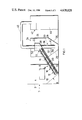
- FIG. 1 is a diagrammatic illustration of the invention
- FIG. 2 is a diagrammatic sectioned view of an alternative form of a detail shown in FIG. 1;
- FIG. 3 is a fragmentary side view of an alternative of a detail shown in FIG. 1;
- FIG. 4 is an end view of the detail shown in FIG. 3.
- combustion equipment 1 including a housing 2 defining a combustion zone 4 in which is located a retort 6 of an underfeed stoker, the remaining components of which have been omitted for the sake of clarity.
- An ash collection trough 8 is situated beneath the retort 6 and is provided with sloping side walls 10.
- a screw 12 of a conveyor and crusher 14 extends into the ash collection trough 8 and is inclined at a similar angle to that of the adjacent wall 10 of the trough 8.
- the screw 12 is housed for substantially the whole of its length within the trough 8 to provide an inlet region 18.
- the screw 12 has short robust flights 20 increasing in pitch from the inlet region 18 and is provided with a drive means (not shown) which may be common with that for the screw conveyor (not shown) of the underfeed stoker.
- the tube 16 terminates in an outlet region 17 and opens into the base of an open-topped hopper 22 which is disposed at an elevated level within a container 24, the base thereof having sloping walls 26 defining an ash receiving zone 28.
- a suction nozzle is shown generally at 30 and includes an outer tube 32 which passes through the top 34 of container 24 and terminates within the ash receiving zone 28, and an inner tube 36 arranged concentrically within tube 32 defining an annular passage 38 therebetween.
- the inner tube 36 protrudes beyond the end of tube 32 and extends the whole length of tube 32 and terminates exteriorly thereof for connection to a conduit 40 leading to a vacuum generating device 42 provided with an ash depository 44.
- solid fuel is burnt within the retort 6 to which the fuel is fed by a screw and ascends within the retort during combustion.
- Ash residue including any clinker is freely discharged over the lip (not shown) of the retort 6 and descends into the ash collection trough 8 from where it is conveyed and simultaneously crushed by the screw 12 of conveyor and crusher 14.
- the ash 50 is transported through the tube 16 from the inlet region 18 to the outlet region 17 and is discharged into the hopper 22 which gradually fills with ash.
- the vacuum generating device 42 Upon activation of the vacuum generating device 42, air is induced through the annular passage 38 and entrains the crushed ash lying in the zone 28 along the tube 36 into conduit 40 which is advantageously provided with a smooth inner surface to reduce friction losses.
- the nozzle 30 may be vibrated during use to improve pick-up.
- the ash conveyed through conduit 40 is discharged into the depository 44 and is subsequently removed therefrom.
- FIG. 2 there is shown an alternative form of nozzle referenced at 130 which is orientated adjacent a sloping wall 126 of the container 124.
- the nozzle 130 is spaced from the apex of the container 124 to define an entrainment zone 125 and comprises a rectangular-sectioned air passage 127 divided from a similarly sectioned suction passage 129 by a partition 131.
- the air passage 127 is open to atmosphere and the suction passage 129 is connected to a vacuum generating device (not shown).
- the ash 141 is entrained in the zone 125 by the induced air flow which impinges on the particles. As can be seen the sharp change in direction of the air flow is of advantage in creating effective entrainment conditions.
- a side discharge aperture 200 is provided in the discharge end 217 of casing 216 and in this region there is affixed to the shaft 201 of the screw 212 a length of bar 202 axially along the length of the shaft.
- the ash is crushed and conveyed by the conveyor and crusher 214 and upon reaching the aperture 200 is forced therethrough by the bar 202, thereby to be discharged into the hopper (not shown in FIGS. 3 and 4).
- the present invention thus affords a means whereby ash created as a result of combustion can be disposed of effectively, cleanly and automatically.
- the container 24 will be of sufficient capacity to enable operations of the suction nozzle only once or twice a day in order to clear the total ash produced by the underfeed stoker combustion even at full output condition.
Abstract
Description
Claims (14)
Applications Claiming Priority (2)
| Application Number | Priority Date | Filing Date | Title |
|---|---|---|---|
| GB8332266 | 1983-12-02 | ||
| GB838332266A GB8332266D0 (en) | 1983-12-02 | 1983-12-02 | Ash handling systems for combustion equipment |
Publications (1)
| Publication Number | Publication Date |
|---|---|
| US4628828A true US4628828A (en) | 1986-12-16 |
Family
ID=10552751
Family Applications (1)
| Application Number | Title | Priority Date | Filing Date |
|---|---|---|---|
| US06/668,715 Expired - Fee Related US4628828A (en) | 1983-12-02 | 1984-11-06 | Ash handling systems for combustion equipment |
Country Status (3)
| Country | Link |
|---|---|
| US (1) | US4628828A (en) |
| DE (1) | DE3440725A1 (en) |
| GB (2) | GB8332266D0 (en) |
Cited By (15)
| Publication number | Priority date | Publication date | Assignee | Title |
|---|---|---|---|---|
| US4738206A (en) * | 1986-09-16 | 1988-04-19 | Roy F. Weston, Inc. | Apparatus and method for low temperature thermal stripping of volatile organic compounds from soil |
| US4787321A (en) * | 1987-03-26 | 1988-11-29 | Howbeit, Inc. | Solid waste conversion plant |
| US4798533A (en) * | 1988-06-06 | 1989-01-17 | Collette Jerry R | Asphalt recycling conveyor |
| US4864942A (en) * | 1988-01-14 | 1989-09-12 | Chemical Waste Management Inc. | Process and apparatus for separating organic contaminants from contaminated inert materials |
| USRE33776E (en) * | 1986-09-16 | 1991-12-24 | Roy F. Weston, Inc. | Apparatus and method for low temperature thermal stripping of volatile organic compounds from soil |
| US5090338A (en) * | 1990-03-26 | 1992-02-25 | Mitsui Engineering & Shipbuilding Co., Ltd. | Apparatus and process for treating waste incineration flyash |
| US5176087A (en) * | 1991-12-17 | 1993-01-05 | Roy F. Weston, Inc. | Apparatus and method for low temperature thermal stripping of volatile organic compounds from soil and waste materials with non-oxidative cross-sweep gases |
| US5188041A (en) * | 1991-12-17 | 1993-02-23 | Roy F. Weston, Inc. | Apparatus and method for low temperature thermal stripping of volatile organic compounds from soil and waste materials with non-oxidative co-current gases |
| WO1993006418A1 (en) * | 1991-09-20 | 1993-04-01 | B&B Joint Venture | Processing facility for disposing of infectious medical waste |
| US5255615A (en) * | 1990-03-02 | 1993-10-26 | Mario Magaldi | System for discharging bottom ash from steam-producing boilers |
| USRE34814E (en) * | 1986-01-10 | 1995-01-03 | Magaldi; Mario | Process and apparatus for continuous dry removal of bottom ash |
| US6311630B1 (en) * | 1997-11-12 | 2001-11-06 | Kaakon Teollisuuspalvelu Oy | Method and device for removal of soda melt from a soda recovery unit |
| US6338306B1 (en) | 2000-10-18 | 2002-01-15 | Applied Synergistics, Inc. | Ash handling system |
| US20090266277A1 (en) * | 2006-10-18 | 2009-10-29 | Boildec Oy | Method and device for emptying the floor of a soda recovery boiler |
| US20110232688A1 (en) * | 2008-12-05 | 2011-09-29 | Boildec Oy | method and device for emptying the floor of a black liquor recovery boiler |
Families Citing this family (1)
| Publication number | Priority date | Publication date | Assignee | Title |
|---|---|---|---|---|
| FR2651031B1 (en) * | 1989-08-16 | 1991-10-25 | Colas Des Francs Hubert | DEVICE FOR THE AUTOMATIC FEEDING OF A COAL GRAIN BOILER WITH AUTOMATIC SCORING RECOVERY |
Citations (25)
| Publication number | Priority date | Publication date | Assignee | Title |
|---|---|---|---|---|
| US1971716A (en) * | 1930-06-26 | 1934-08-28 | Reliance Electric & Eng Co | Ash remover |
| US2506782A (en) * | 1945-05-21 | 1950-05-09 | Fallon John | Automatic ash level control mechanism for gas producer units |
| US3146918A (en) * | 1962-06-11 | 1964-09-01 | Edward C Williams | Particulate material feeding apparatus |
| US3729105A (en) * | 1971-09-27 | 1973-04-24 | Inst Gas Technology | Liquid sealed solids lock hopper |
| US3771643A (en) * | 1971-04-14 | 1973-11-13 | Smidth & Co As F L | Start-reversing vertical screw elevator |
| US3841465A (en) * | 1972-03-06 | 1974-10-15 | Awt Systems Inc | Solids feed to a pressurized reactor |
| US3863577A (en) * | 1971-11-22 | 1975-02-04 | Dorr Oliver Inc | Fluidized bed reactor |
| US3951081A (en) * | 1973-06-27 | 1976-04-20 | Josef Martin Feuerungsbau Gmbh | Method and apparatus for incinerating of refuse |
| US4009667A (en) * | 1975-05-05 | 1977-03-01 | Tyer Robert C | Incinerator for combustible refuse |
| US4041906A (en) * | 1976-04-14 | 1977-08-16 | Edwards Raymond S | Energy system producing electricity, hot water and steam from combustible refuse |
| US4057978A (en) * | 1976-02-17 | 1977-11-15 | Sumitomo Heavy Industries, Ltd. | Apparatus for cooling pellets |
| US4073244A (en) * | 1975-06-09 | 1978-02-14 | Macawber Engineering Limited | Material handling apparatus |
| US4156392A (en) * | 1977-03-30 | 1979-05-29 | Bayeh Paul B | Coal conveying system |
| US4203374A (en) * | 1978-07-17 | 1980-05-20 | Frederick Charles V | Method and means for burning corncobs and corn |
| US4206713A (en) * | 1975-10-17 | 1980-06-10 | The United States Of America As Represented By The Administrator Of The National Aeronautics And Space Administration | Continuous coal processing method |
| US4247240A (en) * | 1979-10-22 | 1981-01-27 | Institute Of Gas Technology | Solids feeder having a solids-liquid separator |
| US4267801A (en) * | 1978-05-31 | 1981-05-19 | Deborah Fluidised Combustion Limited | Circulating fluidized bed boiler |
| US4321876A (en) * | 1980-02-19 | 1982-03-30 | Combustion Engineering, Inc. | System for the removal of ash |
| US4343394A (en) * | 1980-06-23 | 1982-08-10 | Addare Corp. | Apparatus for handling fluent material |
| GB2093585A (en) * | 1981-02-19 | 1982-09-02 | Holden William J | Ash/clinker discharge means for a coal-fired boiler system |
| GB2093960A (en) * | 1981-02-19 | 1982-09-08 | Holden William J | Ash/clinker removal arrangement for a coal-fired boiler system |
| GB2093961A (en) * | 1981-01-09 | 1982-09-08 | Bigwood Joshua & Son Ltd | Solid fuel burners |
| US4426018A (en) * | 1981-06-17 | 1984-01-17 | Ward Dean L | Method and apparatus for recycling scrap |
| US4517903A (en) * | 1983-06-01 | 1985-05-21 | Hunter Enterprises Orillia Limited | Solid fuel furnace |
| US4561596A (en) * | 1981-09-23 | 1985-12-31 | Ab Scaniainventor | Apparatus for spreading granular material |
Family Cites Families (1)
| Publication number | Priority date | Publication date | Assignee | Title |
|---|---|---|---|---|
| DE1175816B (en) * | 1959-07-23 | 1964-08-13 | Consult Ges Fuer Kraft Und Wae | Slag discharge screw conveying upwards at an angle |
-
1983
- 1983-12-02 GB GB838332266A patent/GB8332266D0/en active Pending
-
1984
- 1984-11-06 US US06/668,715 patent/US4628828A/en not_active Expired - Fee Related
- 1984-11-07 DE DE19843440725 patent/DE3440725A1/en not_active Ceased
- 1984-11-09 GB GB08428350A patent/GB2150678B/en not_active Expired
Patent Citations (25)
| Publication number | Priority date | Publication date | Assignee | Title |
|---|---|---|---|---|
| US1971716A (en) * | 1930-06-26 | 1934-08-28 | Reliance Electric & Eng Co | Ash remover |
| US2506782A (en) * | 1945-05-21 | 1950-05-09 | Fallon John | Automatic ash level control mechanism for gas producer units |
| US3146918A (en) * | 1962-06-11 | 1964-09-01 | Edward C Williams | Particulate material feeding apparatus |
| US3771643A (en) * | 1971-04-14 | 1973-11-13 | Smidth & Co As F L | Start-reversing vertical screw elevator |
| US3729105A (en) * | 1971-09-27 | 1973-04-24 | Inst Gas Technology | Liquid sealed solids lock hopper |
| US3863577A (en) * | 1971-11-22 | 1975-02-04 | Dorr Oliver Inc | Fluidized bed reactor |
| US3841465A (en) * | 1972-03-06 | 1974-10-15 | Awt Systems Inc | Solids feed to a pressurized reactor |
| US3951081A (en) * | 1973-06-27 | 1976-04-20 | Josef Martin Feuerungsbau Gmbh | Method and apparatus for incinerating of refuse |
| US4009667A (en) * | 1975-05-05 | 1977-03-01 | Tyer Robert C | Incinerator for combustible refuse |
| US4073244A (en) * | 1975-06-09 | 1978-02-14 | Macawber Engineering Limited | Material handling apparatus |
| US4206713A (en) * | 1975-10-17 | 1980-06-10 | The United States Of America As Represented By The Administrator Of The National Aeronautics And Space Administration | Continuous coal processing method |
| US4057978A (en) * | 1976-02-17 | 1977-11-15 | Sumitomo Heavy Industries, Ltd. | Apparatus for cooling pellets |
| US4041906A (en) * | 1976-04-14 | 1977-08-16 | Edwards Raymond S | Energy system producing electricity, hot water and steam from combustible refuse |
| US4156392A (en) * | 1977-03-30 | 1979-05-29 | Bayeh Paul B | Coal conveying system |
| US4267801A (en) * | 1978-05-31 | 1981-05-19 | Deborah Fluidised Combustion Limited | Circulating fluidized bed boiler |
| US4203374A (en) * | 1978-07-17 | 1980-05-20 | Frederick Charles V | Method and means for burning corncobs and corn |
| US4247240A (en) * | 1979-10-22 | 1981-01-27 | Institute Of Gas Technology | Solids feeder having a solids-liquid separator |
| US4321876A (en) * | 1980-02-19 | 1982-03-30 | Combustion Engineering, Inc. | System for the removal of ash |
| US4343394A (en) * | 1980-06-23 | 1982-08-10 | Addare Corp. | Apparatus for handling fluent material |
| GB2093961A (en) * | 1981-01-09 | 1982-09-08 | Bigwood Joshua & Son Ltd | Solid fuel burners |
| GB2093585A (en) * | 1981-02-19 | 1982-09-02 | Holden William J | Ash/clinker discharge means for a coal-fired boiler system |
| GB2093960A (en) * | 1981-02-19 | 1982-09-08 | Holden William J | Ash/clinker removal arrangement for a coal-fired boiler system |
| US4426018A (en) * | 1981-06-17 | 1984-01-17 | Ward Dean L | Method and apparatus for recycling scrap |
| US4561596A (en) * | 1981-09-23 | 1985-12-31 | Ab Scaniainventor | Apparatus for spreading granular material |
| US4517903A (en) * | 1983-06-01 | 1985-05-21 | Hunter Enterprises Orillia Limited | Solid fuel furnace |
Cited By (20)
| Publication number | Priority date | Publication date | Assignee | Title |
|---|---|---|---|---|
| USRE34814E (en) * | 1986-01-10 | 1995-01-03 | Magaldi; Mario | Process and apparatus for continuous dry removal of bottom ash |
| USRE33776E (en) * | 1986-09-16 | 1991-12-24 | Roy F. Weston, Inc. | Apparatus and method for low temperature thermal stripping of volatile organic compounds from soil |
| US4738206A (en) * | 1986-09-16 | 1988-04-19 | Roy F. Weston, Inc. | Apparatus and method for low temperature thermal stripping of volatile organic compounds from soil |
| US4787321A (en) * | 1987-03-26 | 1988-11-29 | Howbeit, Inc. | Solid waste conversion plant |
| US4864942A (en) * | 1988-01-14 | 1989-09-12 | Chemical Waste Management Inc. | Process and apparatus for separating organic contaminants from contaminated inert materials |
| US4798533A (en) * | 1988-06-06 | 1989-01-17 | Collette Jerry R | Asphalt recycling conveyor |
| US5255615A (en) * | 1990-03-02 | 1993-10-26 | Mario Magaldi | System for discharging bottom ash from steam-producing boilers |
| US5090338A (en) * | 1990-03-26 | 1992-02-25 | Mitsui Engineering & Shipbuilding Co., Ltd. | Apparatus and process for treating waste incineration flyash |
| US5277136A (en) * | 1991-09-20 | 1994-01-11 | Biosafe Inc. | Processing facility for disposing of infectious medical wastes |
| WO1993006418A1 (en) * | 1991-09-20 | 1993-04-01 | B&B Joint Venture | Processing facility for disposing of infectious medical waste |
| EP0908189A2 (en) * | 1991-09-20 | 1999-04-14 | Wsi Medical Waste Systems, Inc. | Processing facility for disposing of infectious medical waste |
| EP0908189A3 (en) * | 1991-09-20 | 1999-09-08 | Wsi Medical Waste Systems, Inc. | Processing facility for disposing of infectious medical waste |
| US5188041A (en) * | 1991-12-17 | 1993-02-23 | Roy F. Weston, Inc. | Apparatus and method for low temperature thermal stripping of volatile organic compounds from soil and waste materials with non-oxidative co-current gases |
| US5176087A (en) * | 1991-12-17 | 1993-01-05 | Roy F. Weston, Inc. | Apparatus and method for low temperature thermal stripping of volatile organic compounds from soil and waste materials with non-oxidative cross-sweep gases |
| US6311630B1 (en) * | 1997-11-12 | 2001-11-06 | Kaakon Teollisuuspalvelu Oy | Method and device for removal of soda melt from a soda recovery unit |
| US6338306B1 (en) | 2000-10-18 | 2002-01-15 | Applied Synergistics, Inc. | Ash handling system |
| US20090266277A1 (en) * | 2006-10-18 | 2009-10-29 | Boildec Oy | Method and device for emptying the floor of a soda recovery boiler |
| US8152965B2 (en) | 2006-10-18 | 2012-04-10 | Boildec Oy | Method and device for emptying the floor of a soda recovery boiler |
| US20110232688A1 (en) * | 2008-12-05 | 2011-09-29 | Boildec Oy | method and device for emptying the floor of a black liquor recovery boiler |
| US8808461B2 (en) | 2008-12-05 | 2014-08-19 | Boildec Oy | Method and device for emptying the floor of a black liquor recovery boiler |
Also Published As
| Publication number | Publication date |
|---|---|
| GB8428350D0 (en) | 1984-12-19 |
| DE3440725A1 (en) | 1985-06-13 |
| GB2150678A (en) | 1985-07-03 |
| GB8332266D0 (en) | 1984-01-11 |
| GB2150678B (en) | 1986-07-30 |
Similar Documents
| Publication | Publication Date | Title |
|---|---|---|
| US4628828A (en) | Ash handling systems for combustion equipment | |
| US3826208A (en) | Apparatus and system for disposing of combustible and waste material | |
| KR20000042375A (en) | Cyclone filter for collecting solid at high temperature | |
| US3030153A (en) | Pneumatic conveyor system | |
| US3397845A (en) | Grinding mill plant | |
| US3577940A (en) | Incinerator | |
| DE3573465D1 (en) | Apparatus for the combustion of solid fuels | |
| US4723494A (en) | Incinerator discharge systems | |
| GB2173389A (en) | Suction system for cigarette machines | |
| SU1160929A3 (en) | Device for cleaning contaminated waste | |
| US4715763A (en) | Dry ash removal system | |
| CN212024159U (en) | Waste residue conveyor of refuse treatment | |
| US1772285A (en) | Method and apparatus for disposing of refuse | |
| US2051282A (en) | Coal burning stoker | |
| US3601068A (en) | System and process for conveyance and incineration of waste material | |
| CN218936355U (en) | Household garbage pyrolysis gasification device | |
| CN217479391U (en) | Biomass efficient gasification system | |
| US4094551A (en) | Material conveying systems | |
| US4080931A (en) | Apparatus for feeding solid fuel to a furnace grate | |
| US2391860A (en) | Steam generator furnace | |
| JPS5625613A (en) | Refuse feeder | |
| JPH0717339U (en) | Vertical mill | |
| JPS567914A (en) | Incinerator | |
| JPS5784714A (en) | Dust collector | |
| SU418407A1 (en) |
Legal Events
| Date | Code | Title | Description |
|---|---|---|---|
| AS | Assignment |
Owner name: COAL INDUSTRY (PATENTS) LIMITED HOBART HOUSE, GROS Free format text: ASSIGNMENT OF ASSIGNORS INTEREST.;ASSIGNORS:HOLTHAM, ROY D.;FALCONER, ANTHONY J.;GRAINGER, JOHN F. G.;REEL/FRAME:004376/0025 Effective date: 19841102 |
|
| FEPP | Fee payment procedure |
Free format text: PAYOR NUMBER ASSIGNED (ORIGINAL EVENT CODE: ASPN); ENTITY STATUS OF PATENT OWNER: LARGE ENTITY |
|
| FPAY | Fee payment |
Year of fee payment: 4 |
|
| REMI | Maintenance fee reminder mailed | ||
| LAPS | Lapse for failure to pay maintenance fees | ||
| FP | Lapsed due to failure to pay maintenance fee |
Effective date: 19951221 |
|
| STCH | Information on status: patent discontinuation |
Free format text: PATENT EXPIRED DUE TO NONPAYMENT OF MAINTENANCE FEES UNDER 37 CFR 1.362 |