US4624352A - Synchronizer spring pin - Google Patents
Synchronizer spring pin Download PDFInfo
- Publication number
- US4624352A US4624352A US06/759,810 US75981085A US4624352A US 4624352 A US4624352 A US 4624352A US 75981085 A US75981085 A US 75981085A US 4624352 A US4624352 A US 4624352A
- Authority
- US
- United States
- Prior art keywords
- spring means
- leg
- spring
- opposed
- detents
- Prior art date
- Legal status (The legal status is an assumption and is not a legal conclusion. Google has not performed a legal analysis and makes no representation as to the accuracy of the status listed.)
- Expired - Fee Related
Links
- 229910000639 Spring steel Inorganic materials 0.000 claims abstract description 6
- 230000000694 effects Effects 0.000 claims description 4
- 230000007935 neutral effect Effects 0.000 claims description 2
- 238000009434 installation Methods 0.000 abstract 1
- 230000005540 biological transmission Effects 0.000 description 8
- 230000013011 mating Effects 0.000 description 5
- 238000013459 approach Methods 0.000 description 2
- 238000004519 manufacturing process Methods 0.000 description 2
- 229910000906 Bronze Inorganic materials 0.000 description 1
- OKTJSMMVPCPJKN-UHFFFAOYSA-N Carbon Chemical compound [C] OKTJSMMVPCPJKN-UHFFFAOYSA-N 0.000 description 1
- 208000013201 Stress fracture Diseases 0.000 description 1
- 239000010974 bronze Substances 0.000 description 1
- 229910052799 carbon Inorganic materials 0.000 description 1
- KUNSUQLRTQLHQQ-UHFFFAOYSA-N copper tin Chemical compound [Cu].[Sn] KUNSUQLRTQLHQQ-UHFFFAOYSA-N 0.000 description 1
- 239000000463 material Substances 0.000 description 1
Images
Classifications
-
- F—MECHANICAL ENGINEERING; LIGHTING; HEATING; WEAPONS; BLASTING
- F16—ENGINEERING ELEMENTS AND UNITS; GENERAL MEASURES FOR PRODUCING AND MAINTAINING EFFECTIVE FUNCTIONING OF MACHINES OR INSTALLATIONS; THERMAL INSULATION IN GENERAL
- F16H—GEARING
- F16H3/00—Toothed gearings for conveying rotary motion with variable gear ratio or for reversing rotary motion
-
- F—MECHANICAL ENGINEERING; LIGHTING; HEATING; WEAPONS; BLASTING
- F16—ENGINEERING ELEMENTS AND UNITS; GENERAL MEASURES FOR PRODUCING AND MAINTAINING EFFECTIVE FUNCTIONING OF MACHINES OR INSTALLATIONS; THERMAL INSULATION IN GENERAL
- F16D—COUPLINGS FOR TRANSMITTING ROTATION; CLUTCHES; BRAKES
- F16D23/00—Details of mechanically-actuated clutches not specific for one distinct type
- F16D23/02—Arrangements for synchronisation, also for power-operated clutches
- F16D23/04—Arrangements for synchronisation, also for power-operated clutches with an additional friction clutch
- F16D23/06—Arrangements for synchronisation, also for power-operated clutches with an additional friction clutch and a blocking mechanism preventing the engagement of the main clutch prior to synchronisation
- F16D23/0606—Arrangements for synchronisation, also for power-operated clutches with an additional friction clutch and a blocking mechanism preventing the engagement of the main clutch prior to synchronisation the blocking mechanism comprising an axially-extending shouldered pin passing through a hole in a radial wall
-
- Y—GENERAL TAGGING OF NEW TECHNOLOGICAL DEVELOPMENTS; GENERAL TAGGING OF CROSS-SECTIONAL TECHNOLOGIES SPANNING OVER SEVERAL SECTIONS OF THE IPC; TECHNICAL SUBJECTS COVERED BY FORMER USPC CROSS-REFERENCE ART COLLECTIONS [XRACs] AND DIGESTS
- Y10—TECHNICAL SUBJECTS COVERED BY FORMER USPC
- Y10T—TECHNICAL SUBJECTS COVERED BY FORMER US CLASSIFICATION
- Y10T74/00—Machine element or mechanism
- Y10T74/19—Gearing
- Y10T74/19219—Interchangeably locked
- Y10T74/19284—Meshing assisters
Definitions
- This invention relates to transmission synchronizer clutch systems of the type including axially opposed blocker rings.
- the rings have opposed friction surfaces positioned for engaging like surfaces on jaw clutch members of selective gears rotatable about a common shaft within the transmission housing.
- the invention relates to spring pins disposed for facilitating engagement of such friction surfaces in response to the selective actuation of a manually operated shifting mechanism.
- Synchronizer clutches of the coacting type are well known in the art of medium duty transmissions. Such clutches are effective to synchronize jaw clutch members prior to contact with and engagement of gear teeth in order to provide shifting without clashing of gears.
- the spring pins typically facilitate engagement of the blocker rings by initially and resiliently moving the friction surfaces into engagement under a relatively low force in response to the incipient engaging movement of the transmission shifting mechanism.
- most of the spring pins systems commonly and currently utilized consist of a plurality of parts, many including separate pin and spring members.
- the prior art spring pins are made typically of stampings and require subsequent assembly of component parts. Even with respect to the simpler prior art structures, the fatigue lives of such spring pin parts have been relatively low.
- the spring pin of the present invention presents a novel, unitary body formed of spring steel, and is considerably simpler to manufacture than most prior art spring pin systems.
- the use of spring steel per se provides a significantly improved fatigue life, providing up to four hundred thousand cycles.
- the spring pin is disposed for operation in a double-acting synchronizer clutch system which includes two axially opposed blocker rings having axially aligned bores for receiving and seating respective ends of the spring pin.
- the spring pin defines an elongated S-shaped body, each end of which defines a bight portion and a spring leg portion spaced from the bight portion in its normally unstressed position.
- oppositely extending outside leg portions of the spring pin each contain a pair of symmetrically opposed detents positioned intermediate the ends of the spring pin body for engagement of a shifter flange.
- the flange is directly coupled to a shifter mechanism and is hence manually operated to effect synchronization and subsequent gear engagement.
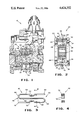
- FIG. 1 is a fragmentary cross-sectional view of a transmission which includes a double-acting clutch synchronizer incorporating a preferred embodiment of the present invention
- FIG. 2 is an enlarged cross-sectional separate view of the double-acting synchronizer clutch system depicted in FIG. 1;
- FIG. 3 is an enlarged detail view of the preferred embodiment of the spring pin incorporated in the clutch synchronizer FIGS. 1 and 2;
- FIG. 4 is a cross-sectional view of the spring pin of FIG. 3 as viewed along lines 4--4 thereof.
- a transmission 10 incorporates a preferred embodiment of a double-acting synchronizer clutch system 20, as separately shown in FIG. 2.
- the transmission 10 includes a rotatable mainshaft 12 containing coaxial gears 14 and 16 positioned thereon.
- Each of the gears 14 and 16 is rotatably mounted on individual bearing systems 18 and 19, respectively, on the rotatable shaft 12.
- the bearing system 18 supporting the gear 14 is of the tapered roller type, while the bearing system 19 supporting the gear 16 is of the fluted type.
- the double-acting synchronizer clutch system 20 incorporates left and right blocker rings 22 and 24, respectively; each preferably made of bronze material for optimal wear.
- the rings 22 and 24 are rigidly secured together by three circumferentially spaced blocker pins 26 (only one of which is shown), which extend axially between the rings. Circumferentially and uniformly spaced intermediately of each pair of blocker pins is a spring pin 40 (only one of which is shown), as will hereinafter be described.
- Each blocker ring contains an internal frustoconical friction surface 28, and each gear 14 and 16 includes a jaw clutch member 6 and 8, respectively, coaxially positioned with respect to the gears.
- Each jaw clutch member contains a mating external frustoconical friction surface 30 disposed for engagement with one of the friction surfaces 28 of the two blocker rings.
- a clutch collar 32 internally splined to the mainshaft 12 as shown at 12'.
- a shifter flange 34 is rigidly coupled to the clutch collar 32 by means of snap rings 38 which axially retain the flange 34 on the collar 32.
- six apertures are uniformly and circumferentially spaced apart within the flange 34 for accommodating the aforenoted three blocker pins 26 and three spring pins 40.
- Each jaw clutch member 6 and 8 contains one set of internal jaw clutch teeth 42 selectively mateable with external jaw clutch teeth 44 on the clutch collar 32.
- the clutch collar is moved from the neutral position shown by means of a manually operated shift fork 46 which is axially movable along a shift rail 47 by an operator of an associated vehicle.
- each spring pin 40 is positioned within a pair of aligned bores or recesses 48, each disposed for receiving one end 50 of a spring pin 40.
- each spring pin 40 includes an opposed pair of detents 52 positioned intermediately on each elongated spring pin body for resiliently securing the shifter flange 34 against axial movement between shifts.
- each aperture 36 of the shifter flange 34 contains a chamfer which provides a cam contact surface 54 for a mating chamfer surface 56 on each blocker pin 26, each mating chamfer surface positioned within a detent 37 on each pin as shown.
- the leftward ends 50 of the spring pins 40 seated in the recesses 48 of the left blocker ring 22 will be effective to shift the entire synchronizer blocker ring system 20 leftwardly, and the friction surface 28 of the ring 22 will then contact the mating friction surface 30 of the jaw clutch member 6.
- the resilience of the spring pin 40 is critical for controlling the incipient frictional movement of the flange apertures 36 with respect to the spring pin detents 52.
- the present inventor has determined that the resilience requirement is most satisfactorily controlled by means of the S-body spring system 40 of the present invention and as shown more particularly in FIG. 3.
- the spring pin 40 not only provides a centering function for the shifter flange 34 between shifts, but that it is also effective to dampen vibration and thereby cut noise during the operational life of the transmission.
- centering of the shifter flange 34 between shifts avoids unnecessary wear of the cam contact surfaces 56, blocker friction surfaces 28, and jaw clutch friction surfaces 30, as will also be appreciated by those skilled in this art.
- the spring pins 40 are formed of a spring steel having a relatively high carbon content, as for example with an SAE range of 1070 to 1090, for the strength and high fatigue life required in this environment A preferred range of Rockwell hardness is 50 to 55.
- the use of spring steel in combination with the S-body shape of the spring pin 40 provides a "radial springiness" aspect sufficient to provide a more satisfactory resilience as well as an improved longevity for the spring pin.
- the use of a single-piece spring pin system provides a manufacturing cost-savings not typically available in prior art spring pin systems.
- each spring pin is formed with a pair of opposed detents 52 as earlier noted, each positioned intermediately of the ends 50 of the elongated body of the spring pin 40.
- Each spring pin defines a first leg 58 and a reversely extending second leg 60, each leg containing one of the pair of detents.
- An intermediate third leg 62 integrally joins the first and second legs 58 and 60 together.
- Each end 50 defines a bight portion 64 and 66, respectively.
- the bight 64 is formed by the integral joinder of the first and intermediate legs, while the bight 66 is formed by the integral joinder of the second and intermediate legs.
- Each end 50 thus defines a bight and a leg end 68,70; the left end 50 defining the afore-described bight 64 and the end 70 of the second leg 60, while the right end 50 defines the bight 66 and the end 68 of the first leg 58.
- the cross section 72 of the spring pin 40 in the preferred embodiment will have rounded corners defined by arcuate edges 74 as shown.
- the present inventor has determined that such edges were effective to avoid stress fracture propogations which otherwise occurred and shortened the fatigue life of the spring pin.
- the cross section approaches that of an oval shape, as generally shown.
Landscapes
- Engineering & Computer Science (AREA)
- General Engineering & Computer Science (AREA)
- Mechanical Engineering (AREA)
- Mechanical Operated Clutches (AREA)
- Springs (AREA)
- Structure Of Transmissions (AREA)
Priority Applications (13)
| Application Number | Priority Date | Filing Date | Title |
|---|---|---|---|
| US06/759,810 US4624352A (en) | 1985-07-29 | 1985-07-29 | Synchronizer spring pin |
| CA000512102A CA1271148A (en) | 1985-07-29 | 1986-06-20 | Synchronizer hollow spring pin |
| DE19863621085 DE3621085A1 (de) | 1985-07-29 | 1986-06-24 | Synchronkupplung fuer getriebe |
| AU59321/86A AU578403B2 (en) | 1985-07-29 | 1986-06-27 | Synchronizer spring pin |
| NL8601700A NL8601700A (nl) | 1985-07-29 | 1986-06-30 | Synchroniseerveerpen. |
| BR8603118A BR8603118A (pt) | 1985-07-29 | 1986-07-03 | Pino de mola de sincronizador |
| GB8616527A GB2178494B (en) | 1985-07-29 | 1986-07-07 | Synchronizer spring pin |
| MX003246A MX166178B (es) | 1985-07-29 | 1986-07-24 | Mejoras en un embrague sincronizador y resorte |
| IT48305/86A IT1195876B (it) | 1985-07-29 | 1986-07-25 | Spinotto a molla per sincronizzatori per autoveicoli |
| SE8603232A SE462118B (sv) | 1985-07-29 | 1986-07-28 | Fjaederanordning vid synkrondon |
| FR868610914A FR2585430B1 (fr) | 1985-07-29 | 1986-07-28 | Cheville-ressort pour mecanisme de synchronisation |
| KR1019860006165A KR950005878B1 (ko) | 1985-07-29 | 1986-07-28 | 변속기의 동기 스프링 핀 |
| JP61176843A JPS6338738A (ja) | 1985-07-29 | 1986-07-29 | 複動シンクロナイザ・クラツチにおけるばね装置 |
Applications Claiming Priority (1)
| Application Number | Priority Date | Filing Date | Title |
|---|---|---|---|
| US06/759,810 US4624352A (en) | 1985-07-29 | 1985-07-29 | Synchronizer spring pin |
Publications (1)
| Publication Number | Publication Date |
|---|---|
| US4624352A true US4624352A (en) | 1986-11-25 |
Family
ID=25057039
Family Applications (1)
| Application Number | Title | Priority Date | Filing Date |
|---|---|---|---|
| US06/759,810 Expired - Fee Related US4624352A (en) | 1985-07-29 | 1985-07-29 | Synchronizer spring pin |
Country Status (13)
| Country | Link |
|---|---|
| US (1) | US4624352A (ko) |
| JP (1) | JPS6338738A (ko) |
| KR (1) | KR950005878B1 (ko) |
| AU (1) | AU578403B2 (ko) |
| BR (1) | BR8603118A (ko) |
| CA (1) | CA1271148A (ko) |
| DE (1) | DE3621085A1 (ko) |
| FR (1) | FR2585430B1 (ko) |
| GB (1) | GB2178494B (ko) |
| IT (1) | IT1195876B (ko) |
| MX (1) | MX166178B (ko) |
| NL (1) | NL8601700A (ko) |
| SE (1) | SE462118B (ko) |
Cited By (8)
| Publication number | Priority date | Publication date | Assignee | Title |
|---|---|---|---|---|
| US5078244A (en) * | 1990-12-24 | 1992-01-07 | Eaton Corporation | Self-energizing synchronizer |
| US5549188A (en) * | 1994-11-01 | 1996-08-27 | Dana Corporation | Split pin for transmission synchronizer assembly |
| USRE35796E (en) * | 1990-12-24 | 1998-05-19 | Eaton Corporation | Self-energizing synchronizer |
| FR2760808A1 (fr) * | 1997-03-11 | 1998-09-18 | Peugeot | Synchoniseur pour boite de vitesses notamment de vehicule automobile |
| US5865287A (en) * | 1996-09-16 | 1999-02-02 | Eaton Corporation | Pin-type synchronizer |
| US5921137A (en) * | 1996-08-19 | 1999-07-13 | Zf Friedrichshafen Ag | Axial support for vehicle gearboxes with helical gear |
| US6658955B1 (en) * | 1999-06-15 | 2003-12-09 | Zf Friedrichshafen Ag | Gearwheel bearing in gearboxes |
| US20040112704A1 (en) * | 2002-08-30 | 2004-06-17 | Mcneill Wulf | Synchronous drive coupling |
Families Citing this family (2)
| Publication number | Priority date | Publication date | Assignee | Title |
|---|---|---|---|---|
| DE19820654B4 (de) * | 1998-05-08 | 2006-11-23 | Schaeffler Kg | Schiebemuffe einer Synchronisiereinheit für Schaltgetriebe |
| KR100941718B1 (ko) * | 2008-03-04 | 2010-02-12 | 현대자동차주식회사 | 스프링 핀 |
Citations (11)
| Publication number | Priority date | Publication date | Assignee | Title |
|---|---|---|---|---|
| US22265A (en) * | 1858-12-07 | Improvement in the manufacture of vulcanized-rubber goods | ||
| US2179568A (en) * | 1937-08-25 | 1939-11-14 | Borg Warner | Transmission synchronizer |
| US2221893A (en) * | 1937-08-25 | 1940-11-19 | Borg Warner | Transmission synchronizer |
| FR1181512A (fr) * | 1957-08-21 | 1959-06-16 | Renault | Dispositif synchroniseur pour pignons de boîtes de vitesses |
| DE1094051B (de) * | 1952-03-20 | 1960-12-01 | Daimler Benz Ag | Synchronisiervorrichtung fuer Klauenkupplungen |
| DE1555158A1 (de) * | 1966-11-02 | 1971-01-14 | Daimler Benz Ag | Vorrichtung zum Synchronisieren von Wechselgetrieben fuer Fahrzeuge,insbesondere fuer Kraftfahrzeuge |
| US3631952A (en) * | 1969-06-21 | 1972-01-04 | Toyota Motor Co Ltd | Integral shifting key for a synchronizing transmission |
| US4252223A (en) * | 1978-12-26 | 1981-02-24 | Eaton Corporation | Transmission with blocker-clutch actuator |
| US4252222A (en) * | 1978-12-26 | 1981-02-24 | Eaton Corporation | Blocker-clutch for synchronized transmission |
| US4462489A (en) * | 1981-07-31 | 1984-07-31 | Eaton Corporation | Synchronizer spring pin |
| US4584892A (en) * | 1982-03-25 | 1986-04-29 | Nissan Motor Co., Ltd. | Manual transmission synchronizer |
Family Cites Families (2)
| Publication number | Priority date | Publication date | Assignee | Title |
|---|---|---|---|---|
| FR844534A (fr) * | 1937-10-11 | 1939-07-26 | Borg Warner | Perfectionnements aux synchroniseurs de transmission |
| DE3212092A1 (de) * | 1982-04-01 | 1983-10-13 | Volkswagenwerk Ag, 3180 Wolfsburg | Synchronringkoerper fuer eine aussenkonus-synchronisierung |
-
1985
- 1985-07-29 US US06/759,810 patent/US4624352A/en not_active Expired - Fee Related
-
1986
- 1986-06-20 CA CA000512102A patent/CA1271148A/en not_active Expired - Lifetime
- 1986-06-24 DE DE19863621085 patent/DE3621085A1/de not_active Withdrawn
- 1986-06-27 AU AU59321/86A patent/AU578403B2/en not_active Ceased
- 1986-06-30 NL NL8601700A patent/NL8601700A/nl not_active Application Discontinuation
- 1986-07-03 BR BR8603118A patent/BR8603118A/pt not_active IP Right Cessation
- 1986-07-07 GB GB8616527A patent/GB2178494B/en not_active Expired
- 1986-07-24 MX MX003246A patent/MX166178B/es unknown
- 1986-07-25 IT IT48305/86A patent/IT1195876B/it active
- 1986-07-28 FR FR868610914A patent/FR2585430B1/fr not_active Expired - Lifetime
- 1986-07-28 KR KR1019860006165A patent/KR950005878B1/ko not_active IP Right Cessation
- 1986-07-28 SE SE8603232A patent/SE462118B/sv not_active IP Right Cessation
- 1986-07-29 JP JP61176843A patent/JPS6338738A/ja active Pending
Patent Citations (11)
| Publication number | Priority date | Publication date | Assignee | Title |
|---|---|---|---|---|
| US22265A (en) * | 1858-12-07 | Improvement in the manufacture of vulcanized-rubber goods | ||
| US2179568A (en) * | 1937-08-25 | 1939-11-14 | Borg Warner | Transmission synchronizer |
| US2221893A (en) * | 1937-08-25 | 1940-11-19 | Borg Warner | Transmission synchronizer |
| DE1094051B (de) * | 1952-03-20 | 1960-12-01 | Daimler Benz Ag | Synchronisiervorrichtung fuer Klauenkupplungen |
| FR1181512A (fr) * | 1957-08-21 | 1959-06-16 | Renault | Dispositif synchroniseur pour pignons de boîtes de vitesses |
| DE1555158A1 (de) * | 1966-11-02 | 1971-01-14 | Daimler Benz Ag | Vorrichtung zum Synchronisieren von Wechselgetrieben fuer Fahrzeuge,insbesondere fuer Kraftfahrzeuge |
| US3631952A (en) * | 1969-06-21 | 1972-01-04 | Toyota Motor Co Ltd | Integral shifting key for a synchronizing transmission |
| US4252223A (en) * | 1978-12-26 | 1981-02-24 | Eaton Corporation | Transmission with blocker-clutch actuator |
| US4252222A (en) * | 1978-12-26 | 1981-02-24 | Eaton Corporation | Blocker-clutch for synchronized transmission |
| US4462489A (en) * | 1981-07-31 | 1984-07-31 | Eaton Corporation | Synchronizer spring pin |
| US4584892A (en) * | 1982-03-25 | 1986-04-29 | Nissan Motor Co., Ltd. | Manual transmission synchronizer |
Cited By (8)
| Publication number | Priority date | Publication date | Assignee | Title |
|---|---|---|---|---|
| US5078244A (en) * | 1990-12-24 | 1992-01-07 | Eaton Corporation | Self-energizing synchronizer |
| USRE35796E (en) * | 1990-12-24 | 1998-05-19 | Eaton Corporation | Self-energizing synchronizer |
| US5549188A (en) * | 1994-11-01 | 1996-08-27 | Dana Corporation | Split pin for transmission synchronizer assembly |
| US5921137A (en) * | 1996-08-19 | 1999-07-13 | Zf Friedrichshafen Ag | Axial support for vehicle gearboxes with helical gear |
| US5865287A (en) * | 1996-09-16 | 1999-02-02 | Eaton Corporation | Pin-type synchronizer |
| FR2760808A1 (fr) * | 1997-03-11 | 1998-09-18 | Peugeot | Synchoniseur pour boite de vitesses notamment de vehicule automobile |
| US6658955B1 (en) * | 1999-06-15 | 2003-12-09 | Zf Friedrichshafen Ag | Gearwheel bearing in gearboxes |
| US20040112704A1 (en) * | 2002-08-30 | 2004-06-17 | Mcneill Wulf | Synchronous drive coupling |
Also Published As
| Publication number | Publication date |
|---|---|
| FR2585430A1 (fr) | 1987-01-30 |
| GB2178494A (en) | 1987-02-11 |
| AU578403B2 (en) | 1988-10-20 |
| SE8603232L (sv) | 1987-01-30 |
| SE462118B (sv) | 1990-05-07 |
| KR950005878B1 (ko) | 1995-06-02 |
| GB8616527D0 (en) | 1986-08-13 |
| KR870001425A (ko) | 1987-03-13 |
| IT1195876B (it) | 1988-10-27 |
| NL8601700A (nl) | 1987-02-16 |
| MX166178B (es) | 1992-12-23 |
| CA1271148A (en) | 1990-07-03 |
| AU5932186A (en) | 1987-02-05 |
| BR8603118A (pt) | 1987-02-17 |
| SE8603232D0 (sv) | 1986-07-28 |
| IT8648305A0 (it) | 1986-07-25 |
| JPS6338738A (ja) | 1988-02-19 |
| FR2585430B1 (fr) | 1990-09-07 |
| DE3621085A1 (de) | 1987-01-29 |
| GB2178494B (en) | 1989-04-19 |
Similar Documents
| Publication | Publication Date | Title |
|---|---|---|
| EP0756098B1 (en) | Synchronizer clutch assembly | |
| EP0652385B1 (en) | Synchronizer clutch assembly for multiple ratio gearing | |
| US4732247A (en) | Triple cone synchronizer with servo action | |
| US4445602A (en) | Gear synchronizer for a power transmission | |
| US5638930A (en) | Strut-type synchronizer | |
| US5135087A (en) | Dual-cone synchronizer with servo action | |
| CA1123631A (en) | Transmission with resilient shifting mechanism | |
| EP0148387B1 (en) | Gear-shift mechanism for manual transmission | |
| US4624352A (en) | Synchronizer spring pin | |
| US4315698A (en) | Coupling sleeve | |
| US5267636A (en) | Synchronizer sliding clutch sleeve | |
| JPS6124584B2 (ko) | ||
| EP0272134B1 (en) | Gear synchronizer mechanism | |
| US4475639A (en) | Clutch assembly for gear transmission | |
| US4721194A (en) | Clutch rocker mechanism for transfer case | |
| US4949589A (en) | Transmission mainshaft gear retainer | |
| US4176736A (en) | Blocked change gear transmission and improved blocker and jaw clutch assembly therefor | |
| US4540074A (en) | Clutch assembly for gear transmission | |
| US4623054A (en) | Dual reversed cone synchronizing clutch | |
| JPS642817B2 (ko) | ||
| EP0291266B1 (en) | Gear synchronizer for power transmission | |
| US6102181A (en) | Clutch with roller fork | |
| US5758753A (en) | Modular synchronizer assembly | |
| EP0846896B1 (en) | Transmission mainshaft thrust washer | |
| KR19980070715A (ko) | 개선된 시프트 요크 |
Legal Events
| Date | Code | Title | Description |
|---|---|---|---|
| AS | Assignment |
Owner name: DANA CORPORATION, TOLEDO OHIO A CORP OF VA Free format text: ASSIGNMENT OF ASSIGNORS INTEREST.;ASSIGNOR:YARNELL, JAMES A.;REEL/FRAME:004437/0396 Effective date: 19850724 |
|
| FPAY | Fee payment |
Year of fee payment: 4 |
|
| FPAY | Fee payment |
Year of fee payment: 8 |
|
| REMI | Maintenance fee reminder mailed | ||
| LAPS | Lapse for failure to pay maintenance fees | ||
| FP | Lapsed due to failure to pay maintenance fee |
Effective date: 19981125 |
|
| AS | Assignment |
Owner name: TRANSMISIONES TSP, S.A. DE C.V., MEXICO Free format text: ASSIGNMENT OF ASSIGNORS INTEREST;ASSIGNOR:DANA CORPORATION;REEL/FRAME:010841/0037 Effective date: 19970902 |
|
| STCH | Information on status: patent discontinuation |
Free format text: PATENT EXPIRED DUE TO NONPAYMENT OF MAINTENANCE FEES UNDER 37 CFR 1.362 |