US4616533A - Stripping device for coaxial cables - Google Patents
Stripping device for coaxial cables Download PDFInfo
- Publication number
- US4616533A US4616533A US06/636,541 US63654184A US4616533A US 4616533 A US4616533 A US 4616533A US 63654184 A US63654184 A US 63654184A US 4616533 A US4616533 A US 4616533A
- Authority
- US
- United States
- Prior art keywords
- cable
- knife
- guiding track
- knife holder
- handle member
- Prior art date
- Legal status (The legal status is an assumption and is not a legal conclusion. Google has not performed a legal analysis and makes no representation as to the accuracy of the status listed.)
- Expired - Fee Related
Links
- 238000009413 insulation Methods 0.000 claims abstract description 17
- 230000004308 accommodation Effects 0.000 claims 2
- 210000000078 claw Anatomy 0.000 description 7
- 239000000463 material Substances 0.000 description 6
- 238000000034 method Methods 0.000 description 4
- 238000003780 insertion Methods 0.000 description 2
- 230000037431 insertion Effects 0.000 description 2
- 230000000994 depressogenic effect Effects 0.000 description 1
- 230000000694 effects Effects 0.000 description 1
- 230000000149 penetrating effect Effects 0.000 description 1
- 239000004033 plastic Substances 0.000 description 1
- 229920003023 plastic Polymers 0.000 description 1
- 230000001681 protective effect Effects 0.000 description 1
- 230000000717 retained effect Effects 0.000 description 1
Images


Classifications
-
- H—ELECTRICITY
- H02—GENERATION; CONVERSION OR DISTRIBUTION OF ELECTRIC POWER
- H02G—INSTALLATION OF ELECTRIC CABLES OR LINES, OR OF COMBINED OPTICAL AND ELECTRIC CABLES OR LINES
- H02G1/00—Methods or apparatus specially adapted for installing, maintaining, repairing or dismantling electric cables or lines
- H02G1/12—Methods or apparatus specially adapted for installing, maintaining, repairing or dismantling electric cables or lines for removing insulation or armouring from cables, e.g. from the end thereof
- H02G1/1202—Methods or apparatus specially adapted for installing, maintaining, repairing or dismantling electric cables or lines for removing insulation or armouring from cables, e.g. from the end thereof by cutting and withdrawing insulation
- H02G1/1204—Hand-held tools
- H02G1/1221—Hand-held tools the cutting element rotating about the wire or cable
- H02G1/1224—Hand-held tools the cutting element rotating about the wire or cable making a transverse cut
Definitions
- the invention refers to a stripping device or apparatus for coaxial cables, and specifically to a device of the kind comprising a guiding track for a terminal portion of the cable which shall be stripped, and at least two knives which may be moved around the cable in a rotational movement and which initially perform only a short incision in the insulating sheathing of the cable, whereupon this incision is by said rotary motion extended to the whole periphery of the cable.
- a coaxial cable comprises, as known, a conductive core, an inner insulating sheathing enveloping the core, an outer conductive layer (shielding layer) enveloping the inner insulating sheathing, and an outer insulating sheathing enveloping the outher conductive layer.
- all said incisions are at first locally limited and afterwards extended to the whole circumference of the cable by a relative rotation of the knives and the cable.
- the first deepest incision causes the perforated layers to be pushed in the longitudinal direction of the cable.
- the knife performing the second incision and possible also the knife making the third incision obstructs an unimpeded movement of the layers past the place of the second or third incision respectively. Consequently, a certain congestion of material occurs in the relatively short path between adjacent incisions generating increased friction between the cable and the knives penetrating into the insulation. A greater effort is therefore necessary to perform said relative rotational movement.
- the invention is based on the recognition that when the knives become operative successively, the material pushed away by the first incision may unimpededly pass the place of the future second and possibly also third incision in the same way as when an ordinary cable is stripped with the aid of a sole knife and a sole incision.
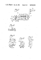
- FIG. 1a and FIG. 1b show the two above mentioned modes of stripping coaxial cables
- FIG. 2 is a side view, partially in section, of a first embodiment of the device according to the invention.
- FIG. 3 is a section along the plane S--S in FIG. 2 through the knife holder of the device of FIG. 2;
- FIG. 4 is an analogous section through a modified embodiment of the knife holder and knives
- FIG. 5 is a side view of a second embodiment of the device according to the invention.
- FIG. 7 is a view in the sense of arrow VII of the upper part of the device of FIG. 6;
- FIG. 8 is a plan view of the knife cartridge of the device of FIG. 6;
- FIG. 9 is a side view on a larger scale of the knife cartridge of the device of FIG. 6;
- FIG. 10 is a view on the same scale as FIG. 9 of the inner side of one of the legs of the yoke-shaped knife holder of the device of FIG. 6;
- FIG. 11 is a front view of three different guiding track inserts.
- FIG. 12 is a plan view on a greater scale of the outer end of the guiding track member in the device of FIG. 6 with one of the guiding track inserts of FIG. 11 in place.
- a coaxial cable 30 may be stripped in such a manner that at a preselected distance A from the cable end Z a first incision is made in a plane I as deep as to the conductive core 34 of the cable.
- a second incision is made in the plane II, but only through the outer insulating layer 31.
- a third incision is made in a plane II', as deep as to the inner insulating layer 33. The severed parts of the insulation are then removed from the cable.
- a device 10 comprises, as shown in FIGS. 2 and 3, an elongate handle member 11, possibly knurled on the surface for better hold by one hand, and in which an axial through-opening 11' is provided.
- a longitudinal, tubular guiding track member 12, also provided with an axial opening 12', is rotarily mounted in the handle member 11 with the aid of mountings 13a, 13a, in such a manner that the two axial openings 11' and 12' are aligned one with another.
- These two openings have such a diameter that any coaxial cable 30 to be stripped which has not a greater diameter than a predetermined maximum value for the respective device may be readily introduced into them.
- a lever 14 which somewhat projects from the surface of the handle member.
- the lever 14 is at one of its ends, preferably at the first end which is more remote from the guiding track member, i.e. at 14', pivotally mounted in the handle member 11 and is at the opposite second end provided with a brake element embodied by a rubber block 14a.
- the material of the guiding track member 12 is, in the part projecting from the handle member 11, along a preselected distance removed to a certain part of the cross-section, e.g. approximately half the cross-section, whereby the axial opening 12' is converted into a trough or support bed for a terminal part of the coaxial cable 30 comprising the sections or distances A+B or A+B+B'. Said trough defines the guiding track 12"proper.
- a settable end stop screw 15 allows an exact setting of the distance A.
- a projecting lever arm 16 pivotally mounted substantially at right angles to the guiding track 12".
- the lever arm 16 is at its free end provided with a rotarily mounted crank handle 16a and defines therewith a crank member.
- an elongate knife holder 17 mounted for limited pivotal movement with the aid of a mounting pin 17'.
- the knife holder 17 extends spacedly along the guiding track 12" and parallelly therewith in operative position.
- the knife holder 17 may be with the aid of a setting knob 17a, provided on the projecting free end of the mounting pin 17', brought into two different end positions defined by a stop pin 18 which projects from the mounting pin 17' and travels in a circular groove in the foot part of the lever arm 16.
- the two end positions may e.g. differ with ⁇ 25° and said circular groove entends then along 50° and the both ends thereof define the two end positions of the knife holder.
- the arrangement is however such that the knives 22 and 23 (the knife 23 is in FIG. 3 totally covered by the knife 22 and therefore not visible) have in cross-sectional direction another angular position than the knife 21.
- the knife holder 17 is brought either in a first end position for operative engagement only of the knife 21, or in a second end position for operative engagement of the knife 22 and a possible third knife 23.
- a stop provided for defining the operative position of the knife holder shown in FIG. 2.
- the stop is settable and is defined by a setting screw 17b the end of which may bear against a not removed part of the guiding track member.
- the rod-shaped knives 21 to 23 may in cross-section preferably have the known shape of a thin biconvex lens, as shown at f.
- the guiding track 12" can be provided a recess 12a at the location of the plane I or S-S.
- the said cross-sectional shape as well as said recess have the purpose to further reduce the friction of the knife relative to the insulation layers, the recess 12a being provided for accomodating a local bulge occuring on the insulation layers when being cut-through.
- the device is operated in the following manner:
- the setting screw 15 is set for a desired length A and the lever arm 16 is pivoted in the sense of arrow P, whereby the knife holder 17 is brought into a rest position in which the guiding track 12" is free from the knives 21 to 23.
- the setting knob 17a may be operated so that the knife holder 17 occupies a non-operative intermediate rotary position (see FIG. 4) in which even in the operative pivotal position of the knife holder according to FIG. 2 no knife is in operative engagement with the cable.
- Said intermediate non-operative rotary position of the knife holder 17 is secured by a spring-loaded ball 18' provided in the foot part of the lever arm 16 and which may slip into a corresponding recess in the mounting pin 17' of the knife holder 17.
- the guiding track 12" rotates thus around the stationary cable 30, pressed against the guiding track by the operating knife.
- the guiding track 12" may be preferably provided with a friction reducing inner lining of some plastics material known for the purpose (see FIG. 11).
- the knob 17a of the knife holder 17 When operating anew, the knob 17a of the knife holder 17 is brought into the second end position where the knife 21 has been removed from the cable and the knives 22 and 23 perform incisions. During at least one further turn are also the incisions of the knives 22 and 23 extended to the whole circumference of the cable 30. Thereupon is the knife holder 17 brought into the rest position by pivoting the lever arm 16 in the sense of arrow P and/or is brought into the non-operative rotary position by operating the knob 17a, and the cable 30 is withdrawn from the device (to the left in FIG. 2). The knife holder 17 may possibly also remain in its operative or engagement position, so that the severed parts are held fast by the knives and stripped off the cable as the cable is drawn out.
- FIG. 4 is shown an alternative embodiment of the knives where the knives 210 and 220 have circular cutting edges 210' and 220' which attack the cable 30, in the same way as the knives 21, 22, from opposite sides, and whose end points 210", 220" move, also in the same manner as the points of the knives 21 and 22 in FIG. 3, along circular paths M and N when being brought into operative position.
- the pivotal movement of the knife holder 17 about the pivot point 16' in FIG. 1 also can be substituted by a rectilinear parallel approachment movement. Either movement may however also be totally omitted when for the introduction of the cable only the above said intermediate non-operative rotary position (e.g. according to FIG. 4) of the knife holder is used.
- a device 10' of this kind is shown in FIG. 5.
- the knife holder 17 is at both sides mounted for limited rotation to a predetermined extent in mounting blocks 160, 162 and extends parallel to the guiding track 12".
- the handle 16a is arranged on an arm 161 which, in the same way as the knob 17a in FIG. 2, is non-rotarily connected with the knife holder 17.
- the knife holder 17 Upon operation of the handle 16a, e.g. by clockwise rotation, the knife holder 17 is first brought into its end position for full operative engagement of the knife 21 with the bolt 18 (FIG. 2) bearing against one end of the circular groove, and then the whole part 12 is rotated. After at least one full turn the handle 16a is operated for rotation in the reverse sense, and the procedure is repeated for the knives 22 and 23 (after the bolt 18 has reached the opposite end of the circular groove).
- the above mentioned stop device with the spring loaded ball 18' is provided for defining the intermediate non-operative rotary position.
- the device 10" according to FIGS. 6 to 12 has an elongate handle member 111, in one end of which is provided a through-opening 111', transverse to the longitudinal direction of the handle member.
- a guiding track member 112 is rotarily mounted in the handle member 111 adjacent the through-opening 111'. The guiding track member projects thus at right angles from the handle member at one side thereof.
- a guiding track 112' is provided in the guiding track member 112 similar to guiding track 12" provided in the guiding track member 12 of FIG. 2
- a yoke-shaped knife holder 117 is with the aid of a pin 116' pivotally mounted at the free end of the guiding track member 112 which is remote from the handle member 111.
- the knife holder 117 has a projecting lever arm 116 which is provided with a crank handle 116a.
- a U-shaped spring 116b holds the knife holder in the pivotal rest position shown in the drawing.
- the spring 116b has two hooked legs which each extends along one side of the knife holder, and a web portion 116b' (FIG. 12) which straddles the end of the guiding track 112'.
- the knife holder 117 has legs 117c, 117d which projects from a web portion 117e and define a central space in which a knife cartridge 120 is accommodated.
- the knife cartridge 120 has essentially the shape of a thick planparallel plate with a front face 120' and a rear face 120" and is provided with a plurality of rectilinear notches such as 120a which extend from the front face 120' to approximately half the thickness of the cartridge 120 and which may be equipped with knives such as 121, 122, 123.
- the notches 120 are locked by a cover plate 120 screwed to the front face 120'.
- tapped bores can according to FIG. 7 be provided at least along a part of the lenth of these notches, and small setting screws 120d (FIG. 8) may be arranged in these holes bearing against the inner ends of the knives.
- the cartridge 120 is mounted in the following manner in order to be easily replaceable by another cartridge, e.g. with otherwise distributed notches.
- 117d At the inner face of each leg 117c, 117d is a key-hole shaped groove 118 provided having a broader circular part 118a with a diameter D and an adjoining narrower straight part 118b having a width B.
- the straight part 118b extends at right angles to the direction of the legs 117c, 117d and of the lever arm 116. From both side faces 120s of the cartridge 120 project short mounting taps 124, 125 defined by two planar and two cylindrical surfaces and whose cross-sectional shape best will be seen in FIG. 9.
- planar faces extend parallel with the front and rear faces 120', 120" of the cartridge 120 at a mutual spacement b corresponding to the width B of the straight part 118b of the notch 118.
- the cylindrical surfaces extend between the planar surfaces at a mutual spacement d corresponding to the diameter D of the circular part 118a of the notch 118.
- the distance e between the longitudinal axis x of the taps 124, 125 and the upper edge 120k" of the rear face 120" corresponds exactly to the distance F between the center C of the circular part 118a of the notch 118 and the lower limiting surface 117'e of the web part 117e.
- the distance h between the longitudinal axis x and the uppger edge 120k' of the front 120' is shorter than the distance e, at least to the extent that it lies on a circular arc drawn from x with a radius equal to the distance between x and 120k".
- the upper face 120c of the cartridge 120 may be curved, tapered, or, as shown in the drawing, broken, i.e. comprising a first planar portion 120c' adjacent and at right angles to the rear face 120", and a second planar portion 120c" sloping relative thereto and adjacent to the front face 120'.
- the cartridge 120 will then be brought into operative position with a certain snap effect depending on the width of said first portion and on the resiliency of the concerned parts.
- the cartridge 120 is with its mounting taps 124, 125 introduced into the groove 118 in such a position that the planar faces of the mounting taps glide along the straight walls of the groove portions 118b, the front face 120' of the cartridge 120 being turned toward the web portion 117e of the knife holder 117.
- the mounting taps 124, 125 have reached the circular groove portions 118a, the cartridge 120 is turned through 90° till the upper edge 120k" bears against the web portion 117e. It will be realised that the above stated distance of the edges 120k' and 120k" allows such a rotation through 90°, but not farther.
- the knives 121 to 123 engage with their arcuate cutting edges such as 121' the cable 30 and press the edge 120k" still more against the web portion 117e.
- the cartridge 120 is first tipped through 90° and then the reverse procedure as upon insertion is applied.
- the locking means in the device 10" consists of an automatic chuck 300 with three elongated clamping jaws 301, 302, 303.
- a potshaped operating member 310 rotarily mounted with its bottom wall 311 turned outwardly.
- the operating member 310 is provided with a milled outer side face 312 which has a diameter K somewhat greater than the width k of the handle member 111, so that the parts 312', 312" of the side wall 312 project laterally from the handle member 111 and can be easily operated by the fingers of the hand which grasps the handle member.
- the pins 313, 314, 315 are stationarily mounted in the handle member 111 around the through-opening 111' at a mutual angular spacement of 180°.
- the pins 313 to 315 have a narrower shank portion, which is not seen in the drawing because it is located beneath the bottom wall 311, and a wider head portion above the bottom wall 311.
- On each shank portion is one of the clamping jaws 301 to 303 rotarily mounted with its free end.
- the bottom wall has at its center a circular orifice 111'a of the through-opening 111' and at the periphery three circular, arcuated slots 323, 324, 325 extending parallel with the side faces 312.
- Projecting engagement pins such as 301a are provided in the clamping jaws 301 to 303 spacedly from the pivot points of the jaws and mesh with the radial slots 333 to 335 in the bottom wall 311.
- a traction spring member 311c provided in the interior of the operating member 310, e.g. between the pin 314 and a pin 311b projecting inwardly from the bottom surface 311, holds the operating member 310 with predetermined force in the position shown in FIG. 7 in which the chuck 300 is closed.
- a protective wall 111a projecting from the handle member 111, protects the finger or fingers which operate the operating member 312 from slipping-off into the region of the knife holder 117.
- the device is operated as follows. By grasping at least one of the parts 312', 312" of the side surface 312, the operating member 312 is turned in the sense of arrow R overcoming the force of the spring means 311c, until the pins 313 to 315 bear against the opposite ends of the slots 313 to 315 than as shown in FIG. 6. Thereby are the clamping jaws 301 to 303 via the slots 333 to 335 and the pins such as 301a pivoted about the pins 313 to 315 so that the orifice 111'a is set free.
- the cable to be stripped is inserted into the through-opening 111' and into the guiding track 112" until it is stopped at 112a". Thereupon is the operating member relieved so that the spring 311c turns it against the sense of the arrow R and the clamping jaws 301 to 303 grasp the cable and via the pins 313 to 315 connect it non-rotarilly with the handle member 111.
- the delay in the engagement of the individual knives is partly due to the fact that any other knife than that which is located closest to the leg 117d projects less from the knife holder, but mainly to the circumstance that any such knife is more spaced from the pivot pin 116' than the afore said knife.
- the pivotal movement in the sense of arrow T is terminated when the lower end 117c' of the leg 117 comes to bear against a collar 112a at the guiding track member 112. Then, or at the utmost a few turns later, also the rotational movement is ceased and the stripping operation is finished.
- the device 10 has the advantage that the user exactly feels with the hand operating the crank handle 116 which resistance any singular cable offers and can determine how fast or slow the pivotal motion in the sense of arrow T, as well as the rotation about the cable, may proceed.
- exchangeable elongated inserts 113a to 113c are preferably provided for the guiding track member 112. All inserts have the same outer diameter, but different inner diameters.
- a slide 114 is arranged at the outside of the guiding track member 112 and is provided (FIG. 12) with bent longitudinal edges 114a, each having at its outer end a projecting engagement claw 114a', 114a". The slide 114 is mounted on the longitudinal edges of the guide track member 112 with the aid of said bent longitudinal edges, one of the engagement claws, e.g. claw 113a, grasping one of the longitudinal edges, e.g.
- the inserts are somewhat shorter than the guiding track, as will be recognised in FIG. 12, and have in their bottom region an opening 113" into which a short pin 112b projects which is arranged in the bottom region of the guiding track member.
- the slide 114 is shorter than the guiding track member (see FIG. 6) and for inserting and removing the inserts 113a to 113c, the slide 114 is pushed to the end of the guiding track which is remote from the handle 111, i.e. to the right in FIG. 12 (arrow Q).
- the engagement claw 114a' leaves the groove 113' and the engagement claw 114a" leaves the longitudinal edge 113a", and the insert may be set on or lifted from the pin 112b.
Landscapes
- Removal Of Insulation Or Armoring From Wires Or Cables (AREA)
Applications Claiming Priority (2)
| Application Number | Priority Date | Filing Date | Title |
|---|---|---|---|
| SE8304627A SE8304627D0 (sv) | 1983-08-26 | 1983-08-26 | Abisoliergeret fur koaxialkabel |
| SE8304627 | 1983-08-26 |
Publications (1)
| Publication Number | Publication Date |
|---|---|
| US4616533A true US4616533A (en) | 1986-10-14 |
Family
ID=20352309
Family Applications (1)
| Application Number | Title | Priority Date | Filing Date |
|---|---|---|---|
| US06/636,541 Expired - Fee Related US4616533A (en) | 1983-08-26 | 1984-08-01 | Stripping device for coaxial cables |
Country Status (4)
| Country | Link |
|---|---|
| US (1) | US4616533A (de) |
| EP (1) | EP0140397B1 (de) |
| DE (1) | DE3482226D1 (de) |
| SE (1) | SE8304627D0 (de) |
Cited By (7)
| Publication number | Priority date | Publication date | Assignee | Title |
|---|---|---|---|---|
| US4730391A (en) * | 1985-12-23 | 1988-03-15 | Warren & Brown & Staff Pty. Ltd. | Wire stripper |
| AU604664B2 (en) * | 1985-12-23 | 1991-01-03 | Warren & Brown & Staff Pty. Ltd. | Wire stripper |
| US6643448B1 (en) * | 2001-04-13 | 2003-11-04 | Wavesplitter Technologies, Inc. | Optical fiber stripping tool |
| US20070037444A1 (en) * | 2005-08-15 | 2007-02-15 | Beam-Chi Jee | Coaxial cable stripper |
| US20090044410A1 (en) * | 2007-08-16 | 2009-02-19 | Kurt Battenfeld | Pliers |
| KR20180057930A (ko) * | 2016-11-23 | 2018-05-31 | 엘에스엠트론 주식회사 | 편조기 |
| US20180152009A1 (en) * | 2015-05-11 | 2018-05-31 | Huber+Suhner Ag | Stripping tool |
Citations (3)
| Publication number | Priority date | Publication date | Assignee | Title |
|---|---|---|---|---|
| US2455591A (en) * | 1944-12-04 | 1948-12-07 | William S Lindsay | Insulation cutting tool |
| US3161088A (en) * | 1962-12-04 | 1964-12-15 | Harold J Tolman | Stripper for coaxial cables |
| US4027557A (en) * | 1976-04-26 | 1977-06-07 | K. Loepfe Automation Ag | Stripping device for wire, or the like |
Family Cites Families (2)
| Publication number | Priority date | Publication date | Assignee | Title |
|---|---|---|---|---|
| US3688404A (en) * | 1970-12-29 | 1972-09-05 | Albert G Muller | Insulation cable cutter |
| SE460939B (sv) | 1980-08-29 | 1989-12-04 | Ca Weidmueller Gmbh & Co | Verktyg foer avisolering av kabelaendar |
-
1983
- 1983-08-26 SE SE8304627A patent/SE8304627D0/xx unknown
-
1984
- 1984-07-16 DE DE8484201056T patent/DE3482226D1/de not_active Expired - Fee Related
- 1984-07-16 EP EP84201056A patent/EP0140397B1/de not_active Expired - Lifetime
- 1984-08-01 US US06/636,541 patent/US4616533A/en not_active Expired - Fee Related
Patent Citations (3)
| Publication number | Priority date | Publication date | Assignee | Title |
|---|---|---|---|---|
| US2455591A (en) * | 1944-12-04 | 1948-12-07 | William S Lindsay | Insulation cutting tool |
| US3161088A (en) * | 1962-12-04 | 1964-12-15 | Harold J Tolman | Stripper for coaxial cables |
| US4027557A (en) * | 1976-04-26 | 1977-06-07 | K. Loepfe Automation Ag | Stripping device for wire, or the like |
Cited By (11)
| Publication number | Priority date | Publication date | Assignee | Title |
|---|---|---|---|---|
| US4730391A (en) * | 1985-12-23 | 1988-03-15 | Warren & Brown & Staff Pty. Ltd. | Wire stripper |
| AU604664B2 (en) * | 1985-12-23 | 1991-01-03 | Warren & Brown & Staff Pty. Ltd. | Wire stripper |
| US6643448B1 (en) * | 2001-04-13 | 2003-11-04 | Wavesplitter Technologies, Inc. | Optical fiber stripping tool |
| US20070037444A1 (en) * | 2005-08-15 | 2007-02-15 | Beam-Chi Jee | Coaxial cable stripper |
| US7316058B2 (en) * | 2005-08-15 | 2008-01-08 | Beam-Chi Jee | Coaxial cable stripper |
| US20090044410A1 (en) * | 2007-08-16 | 2009-02-19 | Kurt Battenfeld | Pliers |
| US8296956B2 (en) | 2007-08-16 | 2012-10-30 | Wezag Gmbh Werkzeugfabrik | Pliers |
| US20180152009A1 (en) * | 2015-05-11 | 2018-05-31 | Huber+Suhner Ag | Stripping tool |
| US11133654B2 (en) | 2015-05-11 | 2021-09-28 | Huber+Suhner Ag | Stripping tool |
| KR20180057930A (ko) * | 2016-11-23 | 2018-05-31 | 엘에스엠트론 주식회사 | 편조기 |
| KR102521045B1 (ko) | 2016-11-23 | 2023-04-11 | 쿠퍼스탠다드오토모티브앤인더스트리얼 주식회사 | 편조기 |
Also Published As
| Publication number | Publication date |
|---|---|
| EP0140397B1 (de) | 1990-05-09 |
| DE3482226D1 (de) | 1990-06-13 |
| SE8304627D0 (sv) | 1983-08-26 |
| EP0140397A3 (en) | 1986-12-10 |
| EP0140397A2 (de) | 1985-05-08 |
Similar Documents
| Publication | Publication Date | Title |
|---|---|---|
| US4640009A (en) | Co-axial cable stripping tool and end portion preparation method | |
| US4945788A (en) | Adjustable-mid-span stripper for wire and cable | |
| US6138362A (en) | Cable stripper | |
| US4682606A (en) | Localizing biopsy apparatus | |
| EP0871270B1 (de) | Handwerkzeug | |
| US5009130A (en) | Coaxial cable stripper | |
| US6128976A (en) | Single drop trimmer | |
| US7984553B1 (en) | Cable preparation tool | |
| US4616533A (en) | Stripping device for coaxial cables | |
| US5713132A (en) | Coaxial cable trimmer | |
| US2761211A (en) | Cable slitter | |
| US20090100681A1 (en) | Coaxial cable stripping tool with adjustable strip stop | |
| US2817255A (en) | Wire stripping tool | |
| US4526068A (en) | Tool for removing insulation | |
| US7503119B2 (en) | Tool for stripping cables | |
| US4447949A (en) | Wire stripper | |
| EP0872003B1 (de) | Abisoliervorrichtung | |
| GB2217119A (en) | Stripping device | |
| US4766672A (en) | Stripping tool | |
| US4459745A (en) | Cable splitter | |
| US5829141A (en) | Device for cutting insulation | |
| US20040055160A1 (en) | Cable stripper | |
| JPH0549135A (ja) | ケーブルストリツパ | |
| US3528325A (en) | Helical cutter | |
| TW201414121A (zh) | 改良手動纜線剝線工具 |
Legal Events
| Date | Code | Title | Description |
|---|---|---|---|
| AS | Assignment |
Owner name: C.A. WEIDMULLER GMBH & CO., P.O.B. 950, D-4940 DET Free format text: ASSIGNMENT OF ASSIGNORS INTEREST.;ASSIGNORS:WIENER, HANS;UNDIN, HANS;REEL/FRAME:004313/0743 Effective date: 19840702 Owner name: C.A. WEIDMULLER GMBH & CO.,GERMANY Free format text: ASSIGNMENT OF ASSIGNORS INTEREST;ASSIGNORS:WIENER, HANS;UNDIN, HANS;REEL/FRAME:004313/0743 Effective date: 19840702 |
|
| FPAY | Fee payment |
Year of fee payment: 4 |
|
| FEPP | Fee payment procedure |
Free format text: PAYOR NUMBER ASSIGNED (ORIGINAL EVENT CODE: ASPN); ENTITY STATUS OF PATENT OWNER: LARGE ENTITY |
|
| REMI | Maintenance fee reminder mailed | ||
| LAPS | Lapse for failure to pay maintenance fees | ||
| FP | Lapsed due to failure to pay maintenance fee |
Effective date: 19941019 |
|
| STCH | Information on status: patent discontinuation |
Free format text: PATENT EXPIRED DUE TO NONPAYMENT OF MAINTENANCE FEES UNDER 37 CFR 1.362 |