US4596233A - Solid fuel combustion equipment - Google Patents
Solid fuel combustion equipment Download PDFInfo
- Publication number
- US4596233A US4596233A US06/434,878 US43487882A US4596233A US 4596233 A US4596233 A US 4596233A US 43487882 A US43487882 A US 43487882A US 4596233 A US4596233 A US 4596233A
- Authority
- US
- United States
- Prior art keywords
- support elements
- sealing means
- equipment according
- grate
- elements
- Prior art date
- Legal status (The legal status is an assumption and is not a legal conclusion. Google has not performed a legal analysis and makes no representation as to the accuracy of the status listed.)
- Expired - Fee Related
Links
Images


Classifications
-
- F—MECHANICAL ENGINEERING; LIGHTING; HEATING; WEAPONS; BLASTING
- F23—COMBUSTION APPARATUS; COMBUSTION PROCESSES
- F23H—GRATES; CLEANING OR RAKING GRATES
- F23H13/00—Grates not covered by any of groups F23H1/00-F23H11/00
- F23H13/06—Dumping grates
-
- F—MECHANICAL ENGINEERING; LIGHTING; HEATING; WEAPONS; BLASTING
- F23—COMBUSTION APPARATUS; COMBUSTION PROCESSES
- F23H—GRATES; CLEANING OR RAKING GRATES
- F23H17/00—Details of grates
- F23H17/12—Fire-bars
-
- F—MECHANICAL ENGINEERING; LIGHTING; HEATING; WEAPONS; BLASTING
- F23—COMBUSTION APPARATUS; COMBUSTION PROCESSES
- F23H—GRATES; CLEANING OR RAKING GRATES
- F23H3/00—Grates with hollow bars
- F23H3/02—Grates with hollow bars internally cooled
-
- F—MECHANICAL ENGINEERING; LIGHTING; HEATING; WEAPONS; BLASTING
- F23—COMBUSTION APPARATUS; COMBUSTION PROCESSES
- F23H—GRATES; CLEANING OR RAKING GRATES
- F23H9/00—Revolving-grates; Rocking or shaking grates
- F23H9/08—Revolving-grates; Rocking or shaking grates the bars being rocked about their longitudinal axes
-
- F—MECHANICAL ENGINEERING; LIGHTING; HEATING; WEAPONS; BLASTING
- F23—COMBUSTION APPARATUS; COMBUSTION PROCESSES
- F23H—GRATES; CLEANING OR RAKING GRATES
- F23H2900/00—Special features of combustion grates
- F23H2900/03021—Liquid cooled grates
Definitions
- This invention concerns improvements in or relating to solid fuel combustion equipment.
- the invention has reference to such equipment intended for use in boilers or furnaces.
- a further problem associated with conventional equipment of the kind referred to is that of ash removal from the combustion zone and more particularly from the mechanism on which the fuel is actually burnt. It can be and very often is the case that clinkering occurs thereby inhibiting both clean and swift ash removal and the continuing combustion process itself. Again, this can have a substantial and serious effect upon the plant relying on the combustion equipment by way of interruption in operation.
- a grate comprising unitary grate bars transversely disposed in relation to the length of the boiler or furnace in which the grate was to be installed, the bars being so mounted as to be tiltable thereby in use enabling the gravitational discharge of ash or other material lying on their upper surfaces into a receiving area beneath the grate.
- a problem associated with this early proposal was that of ensuring that the requisite combustion air passed through the perforated grate bars and did not escape through the interstices therebetween, thereby occasioning imbalanced combustion conditions and the undesirable formation of clinker.
- An object of the present invention is to provide improved solid fuel combustion equipment possessing features which overcome or reduce the problems attendant upon known equipment.
- solid fuel combustion equipment including a grate assembly having at least two longitudinally extending support elements adapted to pivot about the longitudinal axes thereof, a plurality of grate bars arranged on the support elements, and sealing means associated with each support element and cooperable to provide a seal between the elements.
- More than two support elements may be provided, for example four.
- the support elements of the grate assembly may be of box section and in the form of a four sided frame, the grate bars being supported thereon and registering positively therewith in order to be retained during the movement of the elements in use.
- the grate bars may for example be retained on the support elements by bolt arrangements.
- the support elements are advantageously provided with a stub shaft at each end thereof, the stub shaft being connectible to an actuating mechanism associated with the grate assembly and adapted in use to pivot the support elements.
- the support elements being of box section and therefore hollow may provide a flow path for a coolant, for example water, which is pumped therethrough during use to maintain the temperature thereof at an acceptable level.
- the flow paths are constituted within the longitudinal side members of the four sided frame, there being provided a cross-connection between the two side members for the passage of coolant from one side member to the other.
- a shaft at one end of the support element is provided with supply and return passages for the coolant having appropriate input and output connections. Piping from the supply and return passage affords a means of carrying coolant flow to and from the flow paths in the side members of the support elements.
- the sealing means are preferably attachable to the support elements either on a side thereof or depending therefrom, provided that when in use the support elements are in a horizontal or substantially horizontal position, the sealing means cooperate to give a seal between the adjacent support elements to prevent the passage of air or other gas.
- the sealing means are preferably attachable to the support elements through the agency of a resilient mounting which confers upon the sealing means a self-compensating feature for any deviation or relative movement as between the support elements or because of contamination of the sealing areas of the sealing means.
- the method of attachment may comprise a nut and bolt assembly incorporating a spring or equivalent, for example a block of elastomeric material capable of withstanding the high temperature environment in which the resilient mounting has to operate in practice.
- the sealing surfaces of the cooperating sealing means may, in one alternative embodiment, be arcuate and this form is of particular advantage when the support elements come together pivotally in opposite senses, i.e., clockwise and anti-clockwise, the curved surfaces affording a positive and effective rolling and sealing contact.
- the arcuate surfaces may conveniently be part of the circumferential surface of a tubular member extending longitudinally of the support element and having an appropriate mounting arm for attachment to the element through the agency of the aforesaid resilient mounting.
- the tubular members may be replaced by rollers.
- the sealing surfaces of the cooperating sealing means may be linear, one being constituted by a straight edge and the other by a flat or substantially flat surface, either one or both being resiliently mounted.
- An alternative to the straight edge for one of the sealing surfaces may be hemispherical or any arcuate form cooperable with the flat or substantially flat cooperable sealing surface.
- a boiler having a combustion chamber in which is mounted solid fuel combustion equipment according to the first aspect of the invention.
- the wall of the combustion chamber preferably has sealing means cooperable with those of the support element disposed adjacent thereto.
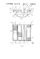
- FIG. 1 is a diagrammatic cross-section of a boiler combustion chamber with the solid fuel combustion equipment mounted therein;
- FIG. 2 is a diagrammatic plan of the view shown in FIG. 1;
- FIG. 3 is a cross-section of a first detail of solid fuel combustion equipment diagrammatically illustrated in FIGS. 1 and 2;
- FIG. 4 is a cross-section of a second detail of such equipment
- FIG. 5 is a cross-section of a third detail of such equipment
- FIG. 6 is a diagrammatic plan view of solid fuel combustion equipment showing cooling arrangements therefor;
- FIG. 7 is a diagrammatic plan view of one of the support elements illustrated in FIG. 6;
- FIG. 8 is a cross section showing the entire grate as partially shown in FIGS. 3 and 4.
- FIGS. 1 and 2 there is depicted a boiler combustion chamber 2 having disposed therein solid fuel combustion equipment in the form of a grate assembly including a grate 4 provided with four support elements 6 extending longitudinally of the chamber.
- Each support element 6 has a shaft 8 at each end thereof to enable pivotal movement of the element caused by an actuating mechanism 9.
- the actuating mechanism may be in the form of fluid operable cylinders, that is pneumatic or hydraulic, controlled either manually or automatically.
- Each support element 6 is of box-section and is in the form of a four sided frame with which a plurality of transverse grate bars 10 registers in closely packed array, the bars 10 being secured to the element 6 by means of bolting arrangements (not shown).
- an ash removal device shown diagrammatically at 12 which may be a vibratory extractor or a screw conveyor or any suitable device for effecting ash discharge from the area 11 beneath the grate 4.
- Each support element 6 has provided along its length sealing means 14 for cooperation with such means on an adjacent element or on the wall of the combustion chamber 2.
- FIG. 3 there is illustrated a form of sealing means 14 employed for the adjacent two middle elements 6.
- the box section sides 16 of the elements 6 are shown and to these sides are affixed the sealing means 14 of which each comprises an angle iron 18 the shorter limb 20 of which is drilled to receive a fixing bolt 22 which passes through the side 16 and is secured by a nut 24, an open coil compression spring 26 being interposed between the nut 24 and the limb 20.
- the longer limb 28 carries a tubular member 30 along its longitudinal edge and a shield plate 32 extends in sloping fashion from the upper part of the side 16 to the top region of the tubular member 30.
- the elements 6 are in a horizontal position and the arcuate sealing surfaces 34 are in contact with one another to seal the space between the two adjacent middle elements 6.
- the arcuate sealing surfaces 34 for those two centre elements 6 were chosen because in operation, the elements when pivoted, move in opposite directions and the curved nature of the surfaces affords a rolling contact effective for the purpose of sealing.
- the sealing means 14 employed between the adjacent sides of the middle elements 6 and the outer elements 6 are shown, the sealing means 14 on one element being different from but cooperable with that of the other elements.
- the right-hand sealing means 14 is constituted by an angle iron 40 secured to an inverted U-shaped channel 42 secured by a bolt 43 to the box-section side 44 of one element 6, an open coil compression spring 46 being interposed between the head of the bolt and the side 44.
- the left-hand sealing means 14 of FIG. 4 comprises an inverted U-shaped channel 48, one side of which terminates in a straight edge 50 which is sealingly cooperable with the flat surface presented by an abutment in the form of one limb 41 of the angle iron 40.
- the U-shaped channel 48 is also resiliently mounted to the box-section side 56 of an adjacent element 6 through the agency of a spring 52 through which extends a securing bolt 54.
- each outer element 6 carries a plate 62 bolted thereto and resiliently mounted by means of a spring 64, the plate 62 having a sealing edge 66.
- An angle iron 68 is secured, by for example, welding to the wall of the combustion chamber 2 and one limb 70 thereof presents a flat sealing surface 72 with which the edge 66 cooperates to form a seal.
- Each support element 6 thus has two sealing means one at each longitudinal margin for the purpose of cooperating with the complementary sealing means of an adjacent support element 6 to prevent in use passage of air therebetween.
- the mating surfaces, whether or curved or linear form afford the necessary seal when the support elements 6 and thus the grate bars 10 are in a horizontal position. It is important to ensure that combustion air does not escape between adjacent elements but merely passes through the grate bars 10 and the fuel bed which in use is supported thereby. If such a sealing arrangement were not provided, clinkering and subsequent fouling of the grate bars would occur thereby giving rise to discontinuous operation with frequent shut-down periods.
- the support elements 6 have cooling paths 80 in the side members 16 and a cross-duct 82 extends therebetween for the flow of coolant from one side member to the other.
- the stub shaft 8 at one end of each support element 6 is drilled to provide a central supply passage 84 and two return passages 86, an input connection 88 being arranged at the end of the shaft 8 and an output connection 90 at a point intermediate the ends of the shaft 8.
- Pipe 92 connects the supply passage 84 to the relatively lower side member 16 and pipe 94 connects the return passages 86 to the relatively upper side member 16 as viewed in the drawings.
- the support elements 6 are pivoted in turn and as shown by the arrows in FIG. 1, the left-hand pair of elements 6 move clockwise in order to discharge ash into the sub-grate area 11 and the right-hand pair moves anti-clockwise.
- the elements 6 may,in use, be pivoted sequentially in a timed manner and automatically or may be pivoted as required upon inspection of the combustion conditions obtaining on the grate 4.
- the air supply to the combustion chamber 2 may be momentarily stopped.
- One advantage of the present invention is that the removal of ash from the grate 4 is swift, thus resulting in little if any interruption in the operation of the boiler or furnace in which the combustion equipment is installed.
- the frequency with which the elements 6 are in use actuated to pivot and discharge ash will depend upon the nature and quality of the ash.
- the support elements 6 are caused to reassume their horizontal positions and advantageously are brought together sharply whereby the complementary sealing means positively engage, indeed impact against one another thereby to ensure not only that effective sealing is achieved but also occasion the removal from the sealing surfaces of any particles which may have adhered thereto.
- the resilient mountings in the form of springs afford a degree of flexibility to compensate for any variations in the orientation of the elements or wear or the equivalent.
- a coolant for example water, is passed through the cooling paths 80 in the side members 16 of the support elements 6 or order to maintain the temperature of the support elements at an acceptable level.
- a further advantage of the present invention lies not only in its inherent capabilities and intended operation but also in its ability to be used as a static grate, should there be any failure, for example in the actuating mechanism for pivotting the elements. The likelihood of such an occurence is remote since there are so few moving parts; however, the supporting elements 6 and the grate bars 10 can be locked in their horizontal positions and removal of ash therefrom is achieved manually.
- the present invention allows of the opportunity to refine the particulates seperated from the exhaust gases into the region beneath the grate wherein they can undergo further combustion with an enhanced residence time since they cannot escape with the combustion gases. At the same time the heat generated by virtue of the combustion is given up to the water surrounding the region beneath the grate.
- the present invention thus couples simplicity with reliability in realizing a practical and innovative way of facilitating ash removal from grates, while maintaining efficient and substantially continuous operation.
Landscapes
- Engineering & Computer Science (AREA)
- Chemical & Material Sciences (AREA)
- Combustion & Propulsion (AREA)
- Mechanical Engineering (AREA)
- General Engineering & Computer Science (AREA)
- Incineration Of Waste (AREA)
- Solid-Fuel Combustion (AREA)
Applications Claiming Priority (2)
| Application Number | Priority Date | Filing Date | Title |
|---|---|---|---|
| GB8131280 | 1981-10-16 | ||
| GB8131280 | 1981-10-16 |
Publications (1)
| Publication Number | Publication Date |
|---|---|
| US4596233A true US4596233A (en) | 1986-06-24 |
Family
ID=10525213
Family Applications (1)
| Application Number | Title | Priority Date | Filing Date |
|---|---|---|---|
| US06/434,878 Expired - Fee Related US4596233A (en) | 1981-10-16 | 1982-10-18 | Solid fuel combustion equipment |
Country Status (8)
| Country | Link |
|---|---|
| US (1) | US4596233A (ref) |
| EP (1) | EP0087531B1 (ref) |
| AU (1) | AU559433B2 (ref) |
| DE (1) | DE3263556D1 (ref) |
| ES (1) | ES8403208A1 (ref) |
| IN (1) | IN158460B (ref) |
| NZ (1) | NZ202133A (ref) |
| ZA (1) | ZA827570B (ref) |
Cited By (3)
| Publication number | Priority date | Publication date | Assignee | Title |
|---|---|---|---|---|
| US5377663A (en) * | 1993-06-07 | 1995-01-03 | Wheelabrator Environmental Systems, Inc. | Grate combustion system |
| WO1999063270A1 (en) * | 1998-05-29 | 1999-12-09 | Fls Miljoe A/S | Water-cooled grate for a combustion furnace |
| WO2009023977A3 (de) * | 2007-08-22 | 2009-06-18 | Doikos Investments Ltd | Flüssigkeitsgekühlte rostplatte mit verschleissplatten und aus solchen rostplatten bestehender stufenrost |
Citations (21)
| Publication number | Priority date | Publication date | Assignee | Title |
|---|---|---|---|---|
| DE169580C (ref) * | ||||
| US85470A (en) * | 1868-12-29 | Improvement in grates | ||
| US605206A (en) * | 1898-06-07 | Andrew pillatt | ||
| US639533A (en) * | 1899-06-09 | 1899-12-19 | Morgan J Cragin | Combined garbage-crematory and water-heater. |
| US742750A (en) * | 1903-01-10 | 1903-10-27 | Nat Malleable Castings Co | Dust-guard for journal-boxes. |
| US808523A (en) * | 1904-06-23 | 1905-12-26 | William Cristian Engel | Grate. |
| US890252A (en) * | 1908-01-22 | 1908-06-09 | Hugh L Thompson | Annealing-furnace. |
| US1064904A (en) * | 1913-01-27 | 1913-06-17 | Oliver D Havard | Transverse dumping-grate. |
| US1586838A (en) * | 1925-06-03 | 1926-06-01 | Edward J Perrey | Furnace |
| GB334757A (en) * | 1929-10-15 | 1930-09-11 | Fuller Lehigh Co | Improvements in furnaces and methods of operating the same |
| DE631003C (de) * | 1936-06-10 | Rheinmetall Borsig Akt Ges Wer | Vorschubrost mit Querreihen von Rostgliedern | |
| US2070349A (en) * | 1935-08-09 | 1937-02-09 | Lcl Corp | Drop bottom container for container cars |
| US2377209A (en) * | 1944-08-07 | 1945-05-29 | Wm Bros Boiler & Mfg Co | Shaker grate construction |
| US2977106A (en) * | 1957-05-08 | 1961-03-28 | Selas Corp Of America | Furnace closure |
| GB1065325A (en) * | 1963-10-15 | 1967-04-12 | Btr Industries Ltd | Improvements in or relating to hose end fittings |
| GB1189290A (en) * | 1968-04-06 | 1970-04-22 | Johannes Josef Martin | Improvements in Furnace Grates |
| US3547152A (en) * | 1968-11-21 | 1970-12-15 | Pacific Air Products | Pressure sealed damper |
| DE2714600A1 (de) * | 1977-04-01 | 1978-10-05 | Peters Ag Claudius | Zweiteilige rostplatte fuer vorschubroste |
| US4294283A (en) * | 1977-11-25 | 1981-10-13 | Scharres Harry J | Wedge sealed damper |
| WO1981003374A1 (en) * | 1980-05-12 | 1981-11-26 | S Johansson | Furnace construction |
| US4320710A (en) * | 1979-03-14 | 1982-03-23 | Widmer & Ernst Ag | Grate mechanism for incinerating furnaces |
Family Cites Families (4)
| Publication number | Priority date | Publication date | Assignee | Title |
|---|---|---|---|---|
| US828769A (en) * | 1905-12-29 | 1906-08-14 | John Elmer Parkison | Grate. |
| GB190723648A (en) * | 1907-10-26 | 1910-03-17 | Farquhar Matheson Mclarty | Improved Fire Bar for Boiler and other Furnaces. |
| GB191124548A (en) * | 1911-11-04 | 1912-08-01 | Charles Claude Carpenter | Improvements relating to High Pressure Incandescent Gas Lamps. |
| US2297784A (en) * | 1939-10-13 | 1942-10-06 | Stephen S Kwolek | Grate |
-
1982
- 1982-10-01 EP EP82305228A patent/EP0087531B1/en not_active Expired
- 1982-10-01 DE DE8282305228T patent/DE3263556D1/de not_active Expired
- 1982-10-08 IN IN743/DEL/82A patent/IN158460B/en unknown
- 1982-10-11 NZ NZ202133A patent/NZ202133A/en unknown
- 1982-10-14 AU AU89385/82A patent/AU559433B2/en not_active Ceased
- 1982-10-15 ZA ZA827570A patent/ZA827570B/xx unknown
- 1982-10-15 ES ES516536A patent/ES8403208A1/es not_active Expired
- 1982-10-18 US US06/434,878 patent/US4596233A/en not_active Expired - Fee Related
Patent Citations (21)
| Publication number | Priority date | Publication date | Assignee | Title |
|---|---|---|---|---|
| DE631003C (de) * | 1936-06-10 | Rheinmetall Borsig Akt Ges Wer | Vorschubrost mit Querreihen von Rostgliedern | |
| US85470A (en) * | 1868-12-29 | Improvement in grates | ||
| US605206A (en) * | 1898-06-07 | Andrew pillatt | ||
| DE169580C (ref) * | ||||
| US639533A (en) * | 1899-06-09 | 1899-12-19 | Morgan J Cragin | Combined garbage-crematory and water-heater. |
| US742750A (en) * | 1903-01-10 | 1903-10-27 | Nat Malleable Castings Co | Dust-guard for journal-boxes. |
| US808523A (en) * | 1904-06-23 | 1905-12-26 | William Cristian Engel | Grate. |
| US890252A (en) * | 1908-01-22 | 1908-06-09 | Hugh L Thompson | Annealing-furnace. |
| US1064904A (en) * | 1913-01-27 | 1913-06-17 | Oliver D Havard | Transverse dumping-grate. |
| US1586838A (en) * | 1925-06-03 | 1926-06-01 | Edward J Perrey | Furnace |
| GB334757A (en) * | 1929-10-15 | 1930-09-11 | Fuller Lehigh Co | Improvements in furnaces and methods of operating the same |
| US2070349A (en) * | 1935-08-09 | 1937-02-09 | Lcl Corp | Drop bottom container for container cars |
| US2377209A (en) * | 1944-08-07 | 1945-05-29 | Wm Bros Boiler & Mfg Co | Shaker grate construction |
| US2977106A (en) * | 1957-05-08 | 1961-03-28 | Selas Corp Of America | Furnace closure |
| GB1065325A (en) * | 1963-10-15 | 1967-04-12 | Btr Industries Ltd | Improvements in or relating to hose end fittings |
| GB1189290A (en) * | 1968-04-06 | 1970-04-22 | Johannes Josef Martin | Improvements in Furnace Grates |
| US3547152A (en) * | 1968-11-21 | 1970-12-15 | Pacific Air Products | Pressure sealed damper |
| DE2714600A1 (de) * | 1977-04-01 | 1978-10-05 | Peters Ag Claudius | Zweiteilige rostplatte fuer vorschubroste |
| US4294283A (en) * | 1977-11-25 | 1981-10-13 | Scharres Harry J | Wedge sealed damper |
| US4320710A (en) * | 1979-03-14 | 1982-03-23 | Widmer & Ernst Ag | Grate mechanism for incinerating furnaces |
| WO1981003374A1 (en) * | 1980-05-12 | 1981-11-26 | S Johansson | Furnace construction |
Cited By (6)
| Publication number | Priority date | Publication date | Assignee | Title |
|---|---|---|---|---|
| US5377663A (en) * | 1993-06-07 | 1995-01-03 | Wheelabrator Environmental Systems, Inc. | Grate combustion system |
| WO1999063270A1 (en) * | 1998-05-29 | 1999-12-09 | Fls Miljoe A/S | Water-cooled grate for a combustion furnace |
| WO2009023977A3 (de) * | 2007-08-22 | 2009-06-18 | Doikos Investments Ltd | Flüssigkeitsgekühlte rostplatte mit verschleissplatten und aus solchen rostplatten bestehender stufenrost |
| US20110232623A1 (en) * | 2007-08-22 | 2011-09-29 | Doikos Investments Limited | Liquid-cooled grill plate comprising wear plates and stepped grill made of such grill plates |
| EA016515B1 (ru) * | 2007-08-22 | 2012-05-30 | Доикос Инвестмент Лимитед | Элемент ступенчатой колосниковой решетки с жидкостным охлаждением и состоящая из таких элементов ступенчатая колосниковая решетка |
| US8590465B2 (en) | 2007-08-22 | 2013-11-26 | Doikos Investments Ltd. | Liquid-cooled grill plate comprising wear plates and stepped grill made of such grill plates |
Also Published As
| Publication number | Publication date |
|---|---|
| DE3263556D1 (en) | 1985-06-20 |
| ZA827570B (en) | 1983-08-31 |
| NZ202133A (en) | 1985-04-30 |
| AU559433B2 (en) | 1987-03-12 |
| EP0087531A1 (en) | 1983-09-07 |
| ES516536A0 (es) | 1984-03-01 |
| AU8938582A (en) | 1983-04-21 |
| EP0087531B1 (en) | 1985-05-15 |
| ES8403208A1 (es) | 1984-03-01 |
| IN158460B (ref) | 1986-11-22 |
Similar Documents
| Publication | Publication Date | Title |
|---|---|---|
| USRE34814E (en) | Process and apparatus for continuous dry removal of bottom ash | |
| US4676176A (en) | Furnace grate | |
| US4596233A (en) | Solid fuel combustion equipment | |
| US5309848A (en) | Reversible, wear-resistant ash screw cooler section | |
| CN108443892A (zh) | 一体式水冷炉排 | |
| US3225721A (en) | Dumping refractory hearth furnace | |
| US4096809A (en) | Apparatus for compensating for thermally induced deformation of sections of grates in industrial furnaces or the like | |
| GB2107838A (en) | Solid fuel combustion equipment | |
| US5103744A (en) | Apparatus for the combustion and/or decomposition of fuel by heat, especially of solid fuels | |
| WO1998023899A1 (en) | Anti-erosion system of grate in stocker type incinerator | |
| US4268244A (en) | Fluid bed furnaces | |
| TW409173B (en) | Grate for incineration plants | |
| US5257587A (en) | Method and apparatus for introducing and incinerating solid combustible waste in a rotary kiln | |
| US4659114A (en) | Rotating pipe joint having a floating seal | |
| WO1992016791A1 (en) | A solid fuel stoker | |
| US5259362A (en) | Sidewall guide for combustion grates | |
| US8051786B2 (en) | Stoker grates for circulating combustible material | |
| US4694757A (en) | Tuyere construction for refuse burning boiler systems | |
| US1460618A (en) | Hand stoker | |
| US2848959A (en) | Fuel burning apparatus | |
| AU645592B2 (en) | Improvements in a solid fuel fired furnace | |
| RU2242673C1 (ru) | Топка | |
| US2704984A (en) | Extension grate for multiple retort stokers | |
| US2449602A (en) | Stoker tuyere | |
| JP5087221B2 (ja) | ストーカ式燃焼装置 |
Legal Events
| Date | Code | Title | Description |
|---|---|---|---|
| AS | Assignment |
Owner name: THORN EMI ENERGY DEVELOPMENTS LIMITED, P.O. BOX 4, Free format text: ASSIGNMENT OF ASSIGNORS INTEREST.;ASSIGNORS:HYDE, JOHN R.;HACKETT, WILLIAM L.;REEL/FRAME:004060/0869 Effective date: 19821014 Owner name: COAL INDUSTRY (PATENTS) LIMITED, HOBART HOUSE, GRO Free format text: ASSIGNMENT OF ASSIGNORS INTEREST.;ASSIGNORS:HYDE, JOHN R.;HACKETT, WILLIAM L.;REEL/FRAME:004060/0869 Effective date: 19821014 |
|
| FEPP | Fee payment procedure |
Free format text: PAYOR NUMBER ASSIGNED (ORIGINAL EVENT CODE: ASPN); ENTITY STATUS OF PATENT OWNER: LARGE ENTITY |
|
| FPAY | Fee payment |
Year of fee payment: 4 |
|
| REMI | Maintenance fee reminder mailed | ||
| LAPS | Lapse for failure to pay maintenance fees | ||
| FP | Lapsed due to failure to pay maintenance fee |
Effective date: 19940629 |
|
| STCH | Information on status: patent discontinuation |
Free format text: PATENT EXPIRED DUE TO NONPAYMENT OF MAINTENANCE FEES UNDER 37 CFR 1.362 |