US4573554A - Disc brake with caliper stabilizing tie-bar - Google Patents
Disc brake with caliper stabilizing tie-bar Download PDFInfo
- Publication number
- US4573554A US4573554A US06/746,923 US74692385A US4573554A US 4573554 A US4573554 A US 4573554A US 74692385 A US74692385 A US 74692385A US 4573554 A US4573554 A US 4573554A
- Authority
- US
- United States
- Prior art keywords
- caliper
- rotor
- connecting member
- bar
- tie
- Prior art date
- Legal status (The legal status is an assumption and is not a legal conclusion. Google has not performed a legal analysis and makes no representation as to the accuracy of the status listed.)
- Expired - Fee Related
Links
- 230000000087 stabilizing effect Effects 0.000 title 1
- 230000003068 static effect Effects 0.000 claims abstract description 9
- 230000003014 reinforcing effect Effects 0.000 abstract 1
- 230000000712 assembly Effects 0.000 description 6
- 238000000429 assembly Methods 0.000 description 6
- 239000012530 fluid Substances 0.000 description 2
- 238000000926 separation method Methods 0.000 description 2
- 210000005069 ears Anatomy 0.000 description 1
- 238000003754 machining Methods 0.000 description 1
- 238000000034 method Methods 0.000 description 1
Images
Classifications
-
- F—MECHANICAL ENGINEERING; LIGHTING; HEATING; WEAPONS; BLASTING
- F16—ENGINEERING ELEMENTS AND UNITS; GENERAL MEASURES FOR PRODUCING AND MAINTAINING EFFECTIVE FUNCTIONING OF MACHINES OR INSTALLATIONS; THERMAL INSULATION IN GENERAL
- F16D—COUPLINGS FOR TRANSMITTING ROTATION; CLUTCHES; BRAKES
- F16D65/00—Parts or details
- F16D65/02—Braking members; Mounting thereof
- F16D65/04—Bands, shoes or pads; Pivots or supporting members therefor
- F16D65/092—Bands, shoes or pads; Pivots or supporting members therefor for axially-engaging brakes, e.g. disc brakes
- F16D65/095—Pivots or supporting members therefor
- F16D65/097—Resilient means interposed between pads and supporting members or other brake parts
- F16D65/0973—Resilient means interposed between pads and supporting members or other brake parts not subjected to brake forces
- F16D65/0974—Resilient means interposed between pads and supporting members or other brake parts not subjected to brake forces acting on or in the vicinity of the pad rim in a direction substantially transverse to the brake disc axis
- F16D65/0975—Springs made from wire
- F16D65/0976—Springs made from wire acting on one pad only
-
- F—MECHANICAL ENGINEERING; LIGHTING; HEATING; WEAPONS; BLASTING
- F16—ENGINEERING ELEMENTS AND UNITS; GENERAL MEASURES FOR PRODUCING AND MAINTAINING EFFECTIVE FUNCTIONING OF MACHINES OR INSTALLATIONS; THERMAL INSULATION IN GENERAL
- F16D—COUPLINGS FOR TRANSMITTING ROTATION; CLUTCHES; BRAKES
- F16D55/00—Brakes with substantially-radial braking surfaces pressed together in axial direction, e.g. disc brakes
- F16D55/02—Brakes with substantially-radial braking surfaces pressed together in axial direction, e.g. disc brakes with axially-movable discs or pads pressed against axially-located rotating members
- F16D55/22—Brakes with substantially-radial braking surfaces pressed together in axial direction, e.g. disc brakes with axially-movable discs or pads pressed against axially-located rotating members by clamping an axially-located rotating disc between movable braking members, e.g. movable brake discs or brake pads
- F16D55/224—Brakes with substantially-radial braking surfaces pressed together in axial direction, e.g. disc brakes with axially-movable discs or pads pressed against axially-located rotating members by clamping an axially-located rotating disc between movable braking members, e.g. movable brake discs or brake pads with a common actuating member for the braking members
- F16D55/225—Brakes with substantially-radial braking surfaces pressed together in axial direction, e.g. disc brakes with axially-movable discs or pads pressed against axially-located rotating members by clamping an axially-located rotating disc between movable braking members, e.g. movable brake discs or brake pads with a common actuating member for the braking members the braking members being brake pads
- F16D55/226—Brakes with substantially-radial braking surfaces pressed together in axial direction, e.g. disc brakes with axially-movable discs or pads pressed against axially-located rotating members by clamping an axially-located rotating disc between movable braking members, e.g. movable brake discs or brake pads with a common actuating member for the braking members the braking members being brake pads in which the common actuating member is moved axially, e.g. floating caliper disc brakes
- F16D55/2265—Brakes with substantially-radial braking surfaces pressed together in axial direction, e.g. disc brakes with axially-movable discs or pads pressed against axially-located rotating members by clamping an axially-located rotating disc between movable braking members, e.g. movable brake discs or brake pads with a common actuating member for the braking members the braking members being brake pads in which the common actuating member is moved axially, e.g. floating caliper disc brakes the axial movement being guided by one or more pins engaging bores in the brake support or the brake housing
- F16D55/227—Brakes with substantially-radial braking surfaces pressed together in axial direction, e.g. disc brakes with axially-movable discs or pads pressed against axially-located rotating members by clamping an axially-located rotating disc between movable braking members, e.g. movable brake discs or brake pads with a common actuating member for the braking members the braking members being brake pads in which the common actuating member is moved axially, e.g. floating caliper disc brakes the axial movement being guided by one or more pins engaging bores in the brake support or the brake housing by two or more pins
-
- F—MECHANICAL ENGINEERING; LIGHTING; HEATING; WEAPONS; BLASTING
- F16—ENGINEERING ELEMENTS AND UNITS; GENERAL MEASURES FOR PRODUCING AND MAINTAINING EFFECTIVE FUNCTIONING OF MACHINES OR INSTALLATIONS; THERMAL INSULATION IN GENERAL
- F16D—COUPLINGS FOR TRANSMITTING ROTATION; CLUTCHES; BRAKES
- F16D55/00—Brakes with substantially-radial braking surfaces pressed together in axial direction, e.g. disc brakes
- F16D2055/0004—Parts or details of disc brakes
- F16D2055/0008—Brake supports
-
- F—MECHANICAL ENGINEERING; LIGHTING; HEATING; WEAPONS; BLASTING
- F16—ENGINEERING ELEMENTS AND UNITS; GENERAL MEASURES FOR PRODUCING AND MAINTAINING EFFECTIVE FUNCTIONING OF MACHINES OR INSTALLATIONS; THERMAL INSULATION IN GENERAL
- F16D—COUPLINGS FOR TRANSMITTING ROTATION; CLUTCHES; BRAKES
- F16D55/00—Brakes with substantially-radial braking surfaces pressed together in axial direction, e.g. disc brakes
- F16D2055/0004—Parts or details of disc brakes
- F16D2055/007—Pins holding the braking members
Definitions
- This invention relates to a disc brake wherein a torque member movably carries a caliper which cooperates with a pair of friction elements to engage the latter with a rotor during braking.
- Disc brakes are being used with heavy vehicles, such as trucks having a gross vehicle weight of 24,000 pounds. Because of the kinetic energy developed by a heavy vehicle, it is necessary to design a disc brake for such a vehicle with larger friction elements, a larger torque member and a larger caliper with more than one piston. Consequently, the disc brake assembly for a heavy vehicle is in itself heavier than normally used with passenger cars. The added weight for the truck disc brake causes the caliper to droop in a static mode as well as lift in a dynamic load. That is, an inner leg of the caliper receiving the pistons is heavier than an outer leg of the caliper, so that an inboard pin assembly supporting the caliper will be loaded radially inward.
- the inner leg will droop or move radially inward and the outer leg will move radially outward. Also, during braking, the friction forces between the friction elements and the rotor will bias the caliper to lift radially outward away from the torque member. With the inner leg of the caliper engaging the pin assembly, the outer leg of the caliper will lift to a greater degree than the inner leg of the caliper.
- the present invention provides a solution to the static droop and the dynamic lift characteristics of the disc brake caliper.
- a disc brake comprising a torque member fixedly secured to a vehicle or the like adjacent a rotor to be braked, a caliper movably carried by the torque member and forming an inner leg on one side of the rotor, an outer leg on the other side of the rotor and a bridge extending axially between the inner and outer legs over an outer edge of the rotor, the caliper cooperating with a pair of friction elements to bias the latter into engagement with the rotor during braking, and a connecting member extending between the inner and outer legs to oppose deflection between the inner and outer legs, characterized in that said torque member includes a tie bar extending circumferentially over a portion of the outer edge of said rotor and contained axially between said pair of friction elements, said tie bar cooperating with said connecting member to define an interface therebetween opposing static droop and dynamic lift when the inner
- the connecting member opposes axial separation between the inner and outer legs of the caliper as well as limiting droop and lift for the caliper.
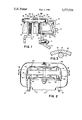
- FIG. 1 is a side offset cross-sectional view of a disc brake constructed in accordance with the present invention.
- FIG. 2 is a top view of the disc brake shown in FIG. 1.
- FIG. 3 is a view taken along line 3--3 of FIG. 1.
- a disc brake 10 includes a torque member 12 secured to a vehicle flange 14 via suitable means such as bolts 16.
- the torque member 12 defines spaced arms 18 and 20 forming a recess 22.
- a pair of pin assemblies 24 and 26, see FIG. 2 are fastened to the torque member to movably carry a caliper 30 with an inner leg 32 in the recess 22, an outer leg 34 facing the inner leg and a bridge 36 connecting the legs 32 and 34.
- the bridge 36 extends over an outer edge 38 of a rotor 40.
- the torque member arms 18 and 20 terminate in axially extending flanges 42 and 44, respectively, extending over the rotor edge 38.
- the flanges 42 and 44 are connected via a tie bar 46 to oppose movement or separation between the flanges 42 and 44.
- a pair of friction elements 48 and 50 are movably carried on the flanges 42 and 44 such that friction element 48 is disposed between rotor 40 and inner leg 32 and friction element 50 is disposed between rotor 40 and outer leg 34.
- the caliper inner leg 32 is formed with a pair of bores, one of which is shown in FIG. 1 at 52, for sealingly receiving a pair of pistons, one of which is shown in FIG. 1 at 54.
- the pistons cooperate with the wall of the bores to form pressure chambers capable of receiving fluid pressure during braking.
- the caliper inner leg 32 forms a radially extending rib 56 between the pair of pistons while the outer leg 34 also forms a radially extending rib 58. Both ribs 56 and 58 are provided with openings 60 and 62, respectively, for receiving a connecting member 64 comprising a bolt 66 and a nut 68.
- the opening 62 is larger than the opening 60 so that a large diameter portion of bolt 66 adjacent head 70 fits within opening 62 and a small diameter portion of bolt 66 adjacent nut 68 fits within opening 60.
- a shoulder 72 on the bolt between the large and small diameter portions abuts the rib 56 to limit the spacing between the ribs when the nut 68 is tightly secured to the bolt.
- the tie bar 46 is provided with a recess 74 defining an arcuate surface 76 substantially matching the outer surface of bolt 66.
- the bolt 66 extends into the recess 74 and is capable of slidably engaging the arcuate surface 76 as described more fully hereinafter.
- the arcuate surface 76 is a smooth surface which provides for the slidable engagement with bolt 66, and may be provided by machining or other suitable methods.
- Each friction element 48 and 50 is provided with transversely extending ears 80 and 82 slidably engaging the radial outer edge of the flanges 42 and 44, respectively.
- the friction elements also abut the inner edge of the respective flanges to transmit braking torque to the torque member 12.
- the bolt 66 extends through openings 84 and 86 on friction elements 48 and 50, respectively, to retain the friction elements in position between the torque member flanges 42 and 44.
- a pair of springs 88 and 90 coil around the bolt 66 and engage the friction elements 48 and 50, respectively, to oppose rattling between the friction elements, the bolt and the flanges.
- the caliper 30 receives fluid pressure during braking to move to the right while the piston 54 moves to the left.
- the friction elements engage the rotor 40 to retard rotation of the latter.
- the inner leg 30 of the caliper includes more mass than the outer leg because the inner leg is provided with the extended bores for receiving the pistons. Consequently, the inner leg transmits a verticle static force to the pin assemblies 24 and 26.
- the verticle static force biases the pin assemblies to bend radially inward slightly about the torque member 12 to lift the outer leg 34 and droop the inner leg 34.
- the bolt 66 is also moved outward to fully engage the tie bar 46 which opposes further lifting of the outer leg.
- the caliper moves further to the right, so that the pin assemblies will be further stressed via the static force biasing the pin assemblies to bend about the torque member.
- the friction elements engage the rotating rotor during braking. Frictional forces are transmitted from the rotor to the friction elements, which, in turn, abut one of the torque member arms to transmit the frictional forces thereto. With the rotor rotating about its axis and the trailing edge of each friction element abutting the torque member, the friction elements are biased outwardly at their leading edge. This outward bias is transmitted to the caliper via the engagement between the friction elements and the inner and outer caliper legs. In addition, the caliper inner and outer legs are loaded in opposite directions tending to lift the caliper radially outwardly.
Abstract
A disc brake includes a caliper cooperating with a pair of friction elements to oppose rotation of a rotor during braking. A torque member supports the caliper and defines a tie bar reinforcing a pair of arms for the torque member. A connecting member extends between a caliper inner and outer leg and cooperates with the tie bar to oppose static caliper droop and dynamic caliper lift.
Description
This is a continuation of application Ser. No. 538,605 filed Oct. 3, 1983, now abandoned.
This invention relates to a disc brake wherein a torque member movably carries a caliper which cooperates with a pair of friction elements to engage the latter with a rotor during braking.
Disc brakes are being used with heavy vehicles, such as trucks having a gross vehicle weight of 24,000 pounds. Because of the kinetic energy developed by a heavy vehicle, it is necessary to design a disc brake for such a vehicle with larger friction elements, a larger torque member and a larger caliper with more than one piston. Consequently, the disc brake assembly for a heavy vehicle is in itself heavier than normally used with passenger cars. The added weight for the truck disc brake causes the caliper to droop in a static mode as well as lift in a dynamic load. That is, an inner leg of the caliper receiving the pistons is heavier than an outer leg of the caliper, so that an inboard pin assembly supporting the caliper will be loaded radially inward. If the pin bends slightly about the torque member in response to the loading, the inner leg will droop or move radially inward and the outer leg will move radially outward. Also, during braking, the friction forces between the friction elements and the rotor will bias the caliper to lift radially outward away from the torque member. With the inner leg of the caliper engaging the pin assembly, the outer leg of the caliper will lift to a greater degree than the inner leg of the caliper.
The prior art is illustrated in U.S. Pat. No. 3,494,448.
The present invention provides a solution to the static droop and the dynamic lift characteristics of the disc brake caliper. In particular, the present invention provides a disc brake comprising a torque member fixedly secured to a vehicle or the like adjacent a rotor to be braked, a caliper movably carried by the torque member and forming an inner leg on one side of the rotor, an outer leg on the other side of the rotor and a bridge extending axially between the inner and outer legs over an outer edge of the rotor, the caliper cooperating with a pair of friction elements to bias the latter into engagement with the rotor during braking, and a connecting member extending between the inner and outer legs to oppose deflection between the inner and outer legs, characterized in that said torque member includes a tie bar extending circumferentially over a portion of the outer edge of said rotor and contained axially between said pair of friction elements, said tie bar cooperating with said connecting member to define an interface therebetween opposing static droop and dynamic lift when the inner leg of said caliper tends to move radially inward and the outer leg of said caliper tends to move radially outward.
It is an advantage of the present invention that the connecting member opposes axial separation between the inner and outer legs of the caliper as well as limiting droop and lift for the caliper.
The accompanying drawings illustrate one embodiment of the invention.
FIG. 1 is a side offset cross-sectional view of a disc brake constructed in accordance with the present invention.
FIG. 2 is a top view of the disc brake shown in FIG. 1.
FIG. 3 is a view taken along line 3--3 of FIG. 1.
A disc brake 10 includes a torque member 12 secured to a vehicle flange 14 via suitable means such as bolts 16. The torque member 12 defines spaced arms 18 and 20 forming a recess 22. A pair of pin assemblies 24 and 26, see FIG. 2, are fastened to the torque member to movably carry a caliper 30 with an inner leg 32 in the recess 22, an outer leg 34 facing the inner leg and a bridge 36 connecting the legs 32 and 34. The bridge 36 extends over an outer edge 38 of a rotor 40.
In FIG. 2, the torque member arms 18 and 20 terminate in axially extending flanges 42 and 44, respectively, extending over the rotor edge 38. The flanges 42 and 44 are connected via a tie bar 46 to oppose movement or separation between the flanges 42 and 44. A pair of friction elements 48 and 50 are movably carried on the flanges 42 and 44 such that friction element 48 is disposed between rotor 40 and inner leg 32 and friction element 50 is disposed between rotor 40 and outer leg 34.
The caliper inner leg 32 is formed with a pair of bores, one of which is shown in FIG. 1 at 52, for sealingly receiving a pair of pistons, one of which is shown in FIG. 1 at 54. The pistons cooperate with the wall of the bores to form pressure chambers capable of receiving fluid pressure during braking. The caliper inner leg 32 forms a radially extending rib 56 between the pair of pistons while the outer leg 34 also forms a radially extending rib 58. Both ribs 56 and 58 are provided with openings 60 and 62, respectively, for receiving a connecting member 64 comprising a bolt 66 and a nut 68. The opening 62 is larger than the opening 60 so that a large diameter portion of bolt 66 adjacent head 70 fits within opening 62 and a small diameter portion of bolt 66 adjacent nut 68 fits within opening 60. A shoulder 72 on the bolt between the large and small diameter portions abuts the rib 56 to limit the spacing between the ribs when the nut 68 is tightly secured to the bolt. The tie bar 46 is provided with a recess 74 defining an arcuate surface 76 substantially matching the outer surface of bolt 66. The bolt 66 extends into the recess 74 and is capable of slidably engaging the arcuate surface 76 as described more fully hereinafter. The arcuate surface 76 is a smooth surface which provides for the slidable engagement with bolt 66, and may be provided by machining or other suitable methods.
Each friction element 48 and 50 is provided with transversely extending ears 80 and 82 slidably engaging the radial outer edge of the flanges 42 and 44, respectively. The friction elements also abut the inner edge of the respective flanges to transmit braking torque to the torque member 12. The bolt 66 extends through openings 84 and 86 on friction elements 48 and 50, respectively, to retain the friction elements in position between the torque member flanges 42 and 44. A pair of springs 88 and 90 coil around the bolt 66 and engage the friction elements 48 and 50, respectively, to oppose rattling between the friction elements, the bolt and the flanges.
Viewing FIG. 1, the caliper 30 receives fluid pressure during braking to move to the right while the piston 54 moves to the left. The friction elements engage the rotor 40 to retard rotation of the latter. The inner leg 30 of the caliper includes more mass than the outer leg because the inner leg is provided with the extended bores for receiving the pistons. Consequently, the inner leg transmits a verticle static force to the pin assemblies 24 and 26. With the pin assemblies secured at one end to the torque member 12, the verticle static force biases the pin assemblies to bend radially inward slightly about the torque member 12 to lift the outer leg 34 and droop the inner leg 34. When the outer leg is lifted, the bolt 66 is also moved outward to fully engage the tie bar 46 which opposes further lifting of the outer leg. As the friction elements are worn, the caliper moves further to the right, so that the pin assemblies will be further stressed via the static force biasing the pin assemblies to bend about the torque member.
In addition to the static forces, the friction elements engage the rotating rotor during braking. Frictional forces are transmitted from the rotor to the friction elements, which, in turn, abut one of the torque member arms to transmit the frictional forces thereto. With the rotor rotating about its axis and the trailing edge of each friction element abutting the torque member, the friction elements are biased outwardly at their leading edge. This outward bias is transmitted to the caliper via the engagement between the friction elements and the inner and outer caliper legs. In addition, the caliper inner and outer legs are loaded in opposite directions tending to lift the caliper radially outwardly.
Claims (2)
1. A disc brake comprising a torque member fixedly secured to a vehicle or the like adjacent a rotor to be braked, a caliper movably carried by the torque member and forming an inner leg on one side of the rotor, an outer leg on the other side of the rotor and a bridge extending axially between the inner and outer legs over an outer edge of the rotor, the caliper cooperating with a pair of friction elements to bias the latter into engagement with the rotor during braking, and a connecting member extending between the inner and outer legs to oppose deflection between the inner and outer legs, characterized in that said torque member includes a tie-bar extending circumferentially over a portion of the outer edge of said rotor and disposed axially between said pair of friction elements, said tie-bar cooperating by direct engagement with said connecting member to define an interface therebetween opposing static droop and dynamic lift when the inner leg of said caliper tends to move radially inwardly and the outer leg of the caliper tends to move radially outwardly, respectively, the tie-bar defining a radial spacing with the portion of the outer edge of said rotor and said connecting member extending through said radial spacing, the interface being formed by sliding engagement between only said connecting member and tie-bar and including an open arcuate recess in an open underside of said tie-bar forming a smooth, machined surface extending circumferentially over only a radially outer portion of the connecting member and facing radially inward, said connecting member extending into said recess so that the radially outer portion of said connecting member slidably engages directly said surface.
2. The disc brake of claim 1, wherein the friction elements include support plates each having an opening therein, said connecting member extending through the openings and supporting a pair of springs which engage said plates to prevent rattling thereof.
Priority Applications (1)
| Application Number | Priority Date | Filing Date | Title |
|---|---|---|---|
| US06/746,923 US4573554A (en) | 1983-10-03 | 1985-06-19 | Disc brake with caliper stabilizing tie-bar |
Applications Claiming Priority (2)
| Application Number | Priority Date | Filing Date | Title |
|---|---|---|---|
| US53860583A | 1983-10-03 | 1983-10-03 | |
| US06/746,923 US4573554A (en) | 1983-10-03 | 1985-06-19 | Disc brake with caliper stabilizing tie-bar |
Related Parent Applications (1)
| Application Number | Title | Priority Date | Filing Date |
|---|---|---|---|
| US53860583A Continuation | 1983-10-03 | 1983-10-03 |
Publications (1)
| Publication Number | Publication Date |
|---|---|
| US4573554A true US4573554A (en) | 1986-03-04 |
Family
ID=27065868
Family Applications (1)
| Application Number | Title | Priority Date | Filing Date |
|---|---|---|---|
| US06/746,923 Expired - Fee Related US4573554A (en) | 1983-10-03 | 1985-06-19 | Disc brake with caliper stabilizing tie-bar |
Country Status (1)
| Country | Link |
|---|---|
| US (1) | US4573554A (en) |
Cited By (8)
| Publication number | Priority date | Publication date | Assignee | Title |
|---|---|---|---|---|
| US5181588A (en) * | 1991-05-06 | 1993-01-26 | Emmons J Bruce | Open framework disc brake caliper having an elastomeric cylinder liner |
| DE4236684A1 (en) * | 1992-10-30 | 1994-05-05 | Teves Gmbh Alfred | Lightweight disc brake in modular construction - has two parts of support frame linked by spacer bolts which locate the brake pads. |
| DE4442794A1 (en) * | 1994-12-01 | 1996-06-05 | Teves Gmbh Alfred | Anti=rattle control spring for pads of disc brake |
| US6334514B1 (en) * | 2000-02-02 | 2002-01-01 | Shimano Inc. | Bicycle disc brake |
| US6341676B2 (en) * | 1998-02-05 | 2002-01-29 | Sanyo Kogyo Co., Ltd. | Electromagnetic brake |
| US6705437B2 (en) * | 2000-06-21 | 2004-03-16 | Haldex Brake Products Ab | Disc brake |
| US20040226784A1 (en) * | 2003-03-28 | 2004-11-18 | Roberto Lavezzi | Caliper of a disc brake |
| WO2013143993A1 (en) * | 2012-03-26 | 2013-10-03 | Knorr-Bremse Systeme für Nutzfahrzeuge GmbH | Brake lining assembly for a floating-caliper disk brake |
Citations (11)
| Publication number | Priority date | Publication date | Assignee | Title |
|---|---|---|---|---|
| US3416634A (en) * | 1967-08-18 | 1968-12-17 | Kelsey Hayes Co | Caliper-type disk brake and support means therefor |
| DE2334232A1 (en) * | 1973-07-05 | 1975-01-23 | Teves Gmbh Alfred | Disc brake with shoe anchor bolt - has clearance between shoe eyes and bolt accommodating return springs |
| US3935927A (en) * | 1973-08-07 | 1976-02-03 | Tokico Ltd. | Disc brake for use in two-wheeled vehicle |
| US3976169A (en) * | 1972-09-19 | 1976-08-24 | Akebono Brake Industry Co., Ltd. | Disc brake |
| US4111285A (en) * | 1973-04-05 | 1978-09-05 | Girling Limited | Slidable caliper and pivotal mounting means therefor |
| DE2850439A1 (en) * | 1977-11-26 | 1979-05-31 | Sumitomo Electric Industries | GUIDING DEVICE WITH A PEN FOR GUIDING A RELATIVE MOVEMENT BETWEEN TWO PARTS |
| US4220224A (en) * | 1978-01-05 | 1980-09-02 | Tokico Ltd. | Disc brake |
| JPS5610837A (en) * | 1979-07-05 | 1981-02-03 | Akebono Brake Ind Co Ltd | Disc brake |
| JPS56143825A (en) * | 1980-03-21 | 1981-11-09 | Sumitomo Electric Ind Ltd | Torque member for disc brake |
| US4341289A (en) * | 1978-09-25 | 1982-07-27 | Lucas Industries Limited | Disc brakes |
| US4530423A (en) * | 1983-10-03 | 1985-07-23 | Allied Corporation | Disc brake including tie bar on stationary torque receiving member |
-
1985
- 1985-06-19 US US06/746,923 patent/US4573554A/en not_active Expired - Fee Related
Patent Citations (11)
| Publication number | Priority date | Publication date | Assignee | Title |
|---|---|---|---|---|
| US3416634A (en) * | 1967-08-18 | 1968-12-17 | Kelsey Hayes Co | Caliper-type disk brake and support means therefor |
| US3976169A (en) * | 1972-09-19 | 1976-08-24 | Akebono Brake Industry Co., Ltd. | Disc brake |
| US4111285A (en) * | 1973-04-05 | 1978-09-05 | Girling Limited | Slidable caliper and pivotal mounting means therefor |
| DE2334232A1 (en) * | 1973-07-05 | 1975-01-23 | Teves Gmbh Alfred | Disc brake with shoe anchor bolt - has clearance between shoe eyes and bolt accommodating return springs |
| US3935927A (en) * | 1973-08-07 | 1976-02-03 | Tokico Ltd. | Disc brake for use in two-wheeled vehicle |
| DE2850439A1 (en) * | 1977-11-26 | 1979-05-31 | Sumitomo Electric Industries | GUIDING DEVICE WITH A PEN FOR GUIDING A RELATIVE MOVEMENT BETWEEN TWO PARTS |
| US4220224A (en) * | 1978-01-05 | 1980-09-02 | Tokico Ltd. | Disc brake |
| US4341289A (en) * | 1978-09-25 | 1982-07-27 | Lucas Industries Limited | Disc brakes |
| JPS5610837A (en) * | 1979-07-05 | 1981-02-03 | Akebono Brake Ind Co Ltd | Disc brake |
| JPS56143825A (en) * | 1980-03-21 | 1981-11-09 | Sumitomo Electric Ind Ltd | Torque member for disc brake |
| US4530423A (en) * | 1983-10-03 | 1985-07-23 | Allied Corporation | Disc brake including tie bar on stationary torque receiving member |
Cited By (11)
| Publication number | Priority date | Publication date | Assignee | Title |
|---|---|---|---|---|
| US5181588A (en) * | 1991-05-06 | 1993-01-26 | Emmons J Bruce | Open framework disc brake caliper having an elastomeric cylinder liner |
| DE4236684A1 (en) * | 1992-10-30 | 1994-05-05 | Teves Gmbh Alfred | Lightweight disc brake in modular construction - has two parts of support frame linked by spacer bolts which locate the brake pads. |
| DE4442794A1 (en) * | 1994-12-01 | 1996-06-05 | Teves Gmbh Alfred | Anti=rattle control spring for pads of disc brake |
| US6341676B2 (en) * | 1998-02-05 | 2002-01-29 | Sanyo Kogyo Co., Ltd. | Electromagnetic brake |
| US6334514B1 (en) * | 2000-02-02 | 2002-01-01 | Shimano Inc. | Bicycle disc brake |
| USRE38975E1 (en) * | 2000-02-02 | 2006-02-14 | Shimano Inc. | Bicycle disc brake |
| US6705437B2 (en) * | 2000-06-21 | 2004-03-16 | Haldex Brake Products Ab | Disc brake |
| US20040226784A1 (en) * | 2003-03-28 | 2004-11-18 | Roberto Lavezzi | Caliper of a disc brake |
| US7007778B2 (en) * | 2003-03-28 | 2006-03-07 | Freni Brembo S.P.A. | Caliper of a disc brake |
| WO2013143993A1 (en) * | 2012-03-26 | 2013-10-03 | Knorr-Bremse Systeme für Nutzfahrzeuge GmbH | Brake lining assembly for a floating-caliper disk brake |
| EP2831457B1 (en) | 2012-03-26 | 2017-07-05 | KNORR-BREMSE Systeme für Nutzfahrzeuge GmbH | Brake lining assembly for a floating-caliper disk brake |
Similar Documents
| Publication | Publication Date | Title |
|---|---|---|
| US6223866B1 (en) | Damped pad spring for use in a disc brake assembly | |
| US4391355A (en) | Sliding caliper disc brake | |
| US3788429A (en) | Disc brake and wheel assembly | |
| EP1069332B1 (en) | Improved disk brake caliper | |
| US4491340A (en) | Vehicle wheel axle and brake mounting assembly | |
| US4613019A (en) | Disk brake assembly | |
| US4573554A (en) | Disc brake with caliper stabilizing tie-bar | |
| US4509619A (en) | Shoe mounted disc brake caliper and shoe support structure | |
| US4540068A (en) | Disc brake | |
| US6257378B1 (en) | Caliper for disc brake assembly | |
| JPS6141025A (en) | Disk brake | |
| US6367598B1 (en) | Rotor for disc brake assembly | |
| US3502181A (en) | Dual circuit,self-energizing disc brake | |
| US4476962A (en) | Disc brake having a sliding yoke | |
| EP0137937B1 (en) | Disc brake | |
| US3005522A (en) | Disc brakes | |
| JPS5831495B2 (en) | drum brake | |
| US6397982B2 (en) | Disc brake housing | |
| EP0035928B1 (en) | Disc brake assembly | |
| WO2009076185A2 (en) | Brake pad for a vehicle disc brake assembly | |
| US4749066A (en) | Disc brake friction pad bolt locking method | |
| US6598716B1 (en) | Rotor for a vehicle brake assembly and method for producing same | |
| US2885035A (en) | Brake mechanism | |
| US5826682A (en) | Disk brake assembly for wheel of a trailer | |
| US4537290A (en) | Sliding caliper disc brake |
Legal Events
| Date | Code | Title | Description |
|---|---|---|---|
| REMI | Maintenance fee reminder mailed | ||
| LAPS | Lapse for failure to pay maintenance fees | ||
| STCH | Information on status: patent discontinuation |
Free format text: PATENT EXPIRED DUE TO NONPAYMENT OF MAINTENANCE FEES UNDER 37 CFR 1.362 |
|
| FP | Lapsed due to failure to pay maintenance fee |
Effective date: 19900304 |
|
| FEPP | Fee payment procedure |
Free format text: PAYOR NUMBER ASSIGNED (ORIGINAL EVENT CODE: ASPN); ENTITY STATUS OF PATENT OWNER: LARGE ENTITY |