US4572523A - Sealing joint and retaining ring for pipe grooved bell and straight spigot joint - Google Patents
Sealing joint and retaining ring for pipe grooved bell and straight spigot joint Download PDFInfo
- Publication number
- US4572523A US4572523A US06/513,999 US51399983A US4572523A US 4572523 A US4572523 A US 4572523A US 51399983 A US51399983 A US 51399983A US 4572523 A US4572523 A US 4572523A
- Authority
- US
- United States
- Prior art keywords
- pipe member
- socket
- packing ring
- retaining ring
- groove
- Prior art date
- Legal status (The legal status is an assumption and is not a legal conclusion. Google has not performed a legal analysis and makes no representation as to the accuracy of the status listed.)
- Expired - Fee Related
Links
- 238000007789 sealing Methods 0.000 title claims description 41
- 238000012856 packing Methods 0.000 claims abstract description 112
- 230000002093 peripheral effect Effects 0.000 claims abstract description 33
- 238000003780 insertion Methods 0.000 claims abstract description 19
- 230000037431 insertion Effects 0.000 claims abstract description 19
- 239000000463 material Substances 0.000 claims abstract description 16
- 230000001154 acute effect Effects 0.000 claims description 5
- 230000004323 axial length Effects 0.000 claims description 5
- 238000010276 construction Methods 0.000 description 7
- 230000005540 biological transmission Effects 0.000 description 4
- 230000006835 compression Effects 0.000 description 3
- 238000007906 compression Methods 0.000 description 3
- 229920003023 plastic Polymers 0.000 description 3
- 239000004033 plastic Substances 0.000 description 3
- 239000012530 fluid Substances 0.000 description 2
- 229920000915 polyvinyl chloride Polymers 0.000 description 2
- 239000004800 polyvinyl chloride Substances 0.000 description 2
- 238000004873 anchoring Methods 0.000 description 1
- 239000004927 clay Substances 0.000 description 1
- 230000018109 developmental process Effects 0.000 description 1
- 239000013536 elastomeric material Substances 0.000 description 1
- -1 for example Substances 0.000 description 1
- 238000004519 manufacturing process Methods 0.000 description 1
- 239000002184 metal Substances 0.000 description 1
- 238000012986 modification Methods 0.000 description 1
- 230000004048 modification Effects 0.000 description 1
- 239000002245 particle Substances 0.000 description 1
Images


Classifications
-
- F—MECHANICAL ENGINEERING; LIGHTING; HEATING; WEAPONS; BLASTING
- F16—ENGINEERING ELEMENTS AND UNITS; GENERAL MEASURES FOR PRODUCING AND MAINTAINING EFFECTIVE FUNCTIONING OF MACHINES OR INSTALLATIONS; THERMAL INSULATION IN GENERAL
- F16L—PIPES; JOINTS OR FITTINGS FOR PIPES; SUPPORTS FOR PIPES, CABLES OR PROTECTIVE TUBING; MEANS FOR THERMAL INSULATION IN GENERAL
- F16L47/00—Connecting arrangements or other fittings specially adapted to be made of plastics or to be used with pipes made of plastics
- F16L47/06—Connecting arrangements or other fittings specially adapted to be made of plastics or to be used with pipes made of plastics with sleeve or socket formed by or in the pipe end
- F16L47/08—Connecting arrangements or other fittings specially adapted to be made of plastics or to be used with pipes made of plastics with sleeve or socket formed by or in the pipe end with sealing rings arranged between the outer surface of one pipe end and the inner surface of the sleeve or socket, the sealing rings being placed previously in the sleeve or socket
- F16L47/10—Connecting arrangements or other fittings specially adapted to be made of plastics or to be used with pipes made of plastics with sleeve or socket formed by or in the pipe end with sealing rings arranged between the outer surface of one pipe end and the inner surface of the sleeve or socket, the sealing rings being placed previously in the sleeve or socket the sealing rings being maintained in place by additional means
-
- F—MECHANICAL ENGINEERING; LIGHTING; HEATING; WEAPONS; BLASTING
- F16—ENGINEERING ELEMENTS AND UNITS; GENERAL MEASURES FOR PRODUCING AND MAINTAINING EFFECTIVE FUNCTIONING OF MACHINES OR INSTALLATIONS; THERMAL INSULATION IN GENERAL
- F16L—PIPES; JOINTS OR FITTINGS FOR PIPES; SUPPORTS FOR PIPES, CABLES OR PROTECTIVE TUBING; MEANS FOR THERMAL INSULATION IN GENERAL
- F16L17/00—Joints with packing adapted to sealing by fluid pressure
- F16L17/02—Joints with packing adapted to sealing by fluid pressure with sealing rings arranged between outer surface of pipe and inner surface of sleeve or socket
- F16L17/03—Joints with packing adapted to sealing by fluid pressure with sealing rings arranged between outer surface of pipe and inner surface of sleeve or socket having annular axial lips
- F16L17/035—Joints with packing adapted to sealing by fluid pressure with sealing rings arranged between outer surface of pipe and inner surface of sleeve or socket having annular axial lips the sealing rings having two lips parallel to each other
-
- F—MECHANICAL ENGINEERING; LIGHTING; HEATING; WEAPONS; BLASTING
- F16—ENGINEERING ELEMENTS AND UNITS; GENERAL MEASURES FOR PRODUCING AND MAINTAINING EFFECTIVE FUNCTIONING OF MACHINES OR INSTALLATIONS; THERMAL INSULATION IN GENERAL
- F16L—PIPES; JOINTS OR FITTINGS FOR PIPES; SUPPORTS FOR PIPES, CABLES OR PROTECTIVE TUBING; MEANS FOR THERMAL INSULATION IN GENERAL
- F16L21/00—Joints with sleeve or socket
- F16L21/02—Joints with sleeve or socket with elastic sealing rings between pipe and sleeve or between pipe and socket, e.g. with rolling or other prefabricated profiled rings
- F16L21/03—Joints with sleeve or socket with elastic sealing rings between pipe and sleeve or between pipe and socket, e.g. with rolling or other prefabricated profiled rings placed in the socket before connection
Definitions
- the invention relates to pipe members and concerns a pipe member having a socket formed by an end portion thereof and a radially outwardly directed annular groove or corrugation in the wall of the pipe member end portion, a packing ring of resiliently deformable material disposed inside the pipe member end portion in the corrugation and a retaining ring received in an internal recess in the packing ring, the packing ring having an outer peripheral portion to fit with the pipe member wall defining the groove, the arrangement being such that an insertion of another or second pipe member into the socket, the packing ring is compressed against the wall of the pipe member defining the groove to seal the gap between the inserted pipe member and the socket.
- Known pipe members of this kind consist, in particular, of plastic material such as polyvinyl chloride.
- the retaining ring consists of a stiffer material than that of the packing ring and has the purpose of holding the packing ring, which is preassembled at the works, captive in the groove in the wall of the pipe member end portion forming the socket, and of facilitating insertion of a further pipe member into the socket during the establishment of a pipe connection.
- the packing ring is provided with a projection disposed axially behind the retaining ring to the side thereof remote from the open end of the socket.
- the projection on insertion of a further pipe member into the socket, forms with the inserted pipe member, a pressure shoulder which acts to compress the packing ring.
- a pipe member having a socket formed by an end portion thereof and a radially outwardly directed annular groove in the wall of the pipe member end portion, a packing ring of resiliently deformable material disposed inside the pipe member end portion in the groove and a retaining ring received in an internal recess in the packing ring.
- the packing ring has an outer peripheral portion which fits with the pipe member wall defining the groove and front having rear projections situated respectively axially in front of and behind the retaining ring to the side thereof adjacent the open end of the socket and to the side thereof remote from the open end of the socket respectively.
- the projections upon insertion of a further pipe member into the socket, form in co-operation with the inserted pipe member pressure shoulders which act to compress the packing ring against the pipe member wall defining the groove over the whole outer peripheral portion of the packing ring.
- the pressure shoulders formed by the front and rear projections give rise to a particularly firm pressing in of the packing ring radially into the groove in the wall of the pipe member end portion, and in the final result, the whole outer peripheral portion of the packing ring, extends over the two pressure shoulders and over the retaining ring, is compressively applied against the pipe member wall defining the groove, closely following its contour.
- the groove is formed as a corrugation in the wall of the pipe member end portion and conveniently also, the groove is of arch shaped contour in axial cross-section of the pipe member.
- Such corrugations which have a contour of gentle, arcuate or smooth lines do not, in themselves, offer the outer peripheral portion of the packing ring any pronounced anchoring or counter-surface for sealing engagement and the present invention is particularly applicable to pipe members in which the annular groove in the wall of the pipe member end portion is of smooth form.
- the front projection of the packing ring situated axially in front of the retaining ring is first pressed into the groove or corrugation thus causing deformation and compression of which, the packing ring executes a small axial forward movement.
- the rear projection of the packing ring is pressed into the groove or corrugation by the inserted pipe member, with further deformation and compression of the packing ring creating, as with a front projection which, the rear projection transmits a compressive force to the outer peripheral portion of the packing ring. This is accompanied by a small axial rearward movement of the packing ring.
- the opposite axial movements of the packing ring and the force components produced in this manner compresses the packing ring, improve the sealing action.
- the internal recess in the packing ring opens inwardly towards the interior of the pipe member in which case, in their uncompressed state, said front and rear projections have a cross-sectional shape which tapers radially inwardly of the pipe member beyond the inner circumference of the retaining ring.
- the retaining ring is visibly held in the internal recess in the packing ring with the ring in its assembled state in the socket of the pipe member and when a further pipe member is inserted into the socket the retaining ring lies spaced from the wall of the inserted pipe member by an amount corresponding to the radial thickness of portions of the front and rear projections or of the front projection held compressed between the wall of the inserted pipe member and the inner circumferential face of the retaining ring, at its front and rear edges or its front edge respectively.
- said front projection has a rearwardly extending inner sealing lip to engage over said internal recess in compressive contact with said rear projection to transmit compressive forces to said rear projection on insertion of a further pipe member into the socket.
- the retaining ring is held practically invisibly in the internal recess in the packing ring with the ring in its assembled state in the socket of the pipe member and when a further pipe member is inserted into the socket, particularly in the installed state in a pipe connection, the inner sealing lip engages over the whole area of the inner face of the retaining ring.
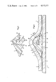
- FIG. 1 is an axial section through a pipe connection comprising a pipe member having an end socket receiving a further pipe member with the inclusion of a packing ring held compressed between the further pipe member and the socket;
- FIG. 2 is an axial section through a packing ring in the uncompressed state thereof;
- FIG. 3 shows the packing ring of FIG. 2 held compressed in a pipe connection as shown in FIG. 1;
- FIGS. 4 and 5 are illustrations corresponding to FIGS. 2 and 3 showing a further construction of packing ring
- FIGS. 6 and 7 are illustrations corresponding to FIG. 2 and each shows a still further construction of packing ring.
- the pipe connection shown in FIG. 1 comprises a pipe member 1 having a socket 2, the wall of which is provided with a radially outwardly directed groove or corrugation 3 extending around it in the form of a ring.
- a packing ring 4 of resiliently deformable material, particularly rubber or an elastomeric material which is held in the corrugation 3 by a retaining ring 5 made of a stiffer material than that of the packing ring 4, and which may be a semi-rigid or of a rigid plastics material.
- the pipe connection also comprises a further pipe member 6 which is assembled by insertion into the socket 2, in the direction of the arrow 7, and which is a push fit in the socket.
- the insertion of the pipe member 6 compresses the packing ring 4 in two stages and in such a manner that the outer peripheral portion of the packing ring 4 is pressed into the groove or corrugation 3 to seal the gap between the wall of the pipe member 6 and the wall of the socket 2 and thus the pipe connection.
- FIGS. 2 to 7 Various forms of packing or sealing ring 4 are illustrated with reference to FIGS. 2 to 7 in illustrations corresponding to the upper half of FIG. 1 to a larger size, any of which may be used in a pipe connection as shown in FIG. 1 and incorporating a pipe member 1 in accordance with the present invention.
- FIGS. 2 and 3 show a packing or sealing ring 8 with an outer peripheral portion 9 contoured to fit within the contour of the groove or corrugation 3.
- the packing ring 8 receives the retaining ring 5 in an internal recess 10 in the packing ring, the roof of which is of toothed construction to take up manufacturing tolerances. Seen in the direction of arrow 7, the packing ring 8 has a front projection 11 disposed axially in front of the retaining ring 5 and a rear projection 12 situated axially behind the retaining ring 5.
- the internal recess 10 in the packing ring 8 opens towards the interior of the pipe 1 so that the retaining ring 5, shown in broken lines in FIG. 2, is visible from the inside of the socket 2 with the packing ring 8 in its assembled state in the socket.
- the two projections 11 and 12 of the packing ring 8 have a cross-sectional shape which is directed substantially radially inwards towards the interior of the pipe and which tapers so as to become narrower in the region projecting beyond the inner peripheral surface 13 of the retaining ring 5. This ensures that the retaining ring 5 does not impair the transmission of compressive forces applied by the projections 11 and 12 to the outer peripheral portion 9 of the packing ring outwardly of the retaining ring.
- the axially front end face 14 and the axially rear end face 15 of the internal recess 10 in the packing ring 8 are formed by opposite end faces of the front and rear projections 11, 12 respectively.
- the free inner edge of the rear projection 12 is disposed substantially in the same circumferential plane as the free inner edge of the front projection 11.
- the packing ring is further provided with a short guide extension 16 which is disposed in front of the front projection 11 in the direction of arrow 7 and which initially is engaged upon the insertion of pipe member 6 to locate the packing ring 8 in the groove or corrugation 3.
- the projections 11 and 12 are compressed by the pipe member 6 and form pressure shoulders which act to compress the packing ring 8 into the annular groove or corrugation 3.
- the pipe member 6 first engages the projection 11 and at first presses the packing ring 8 primarily against the wall 17 of the groove or corrugation 3.
- the pipe member 6 then engages the projection 12 and the latter presses the packing ring 8 primarily against the wall 18 of the groove or corrugation, the packing ring executing an axial reciprocating movement as oppositely directed components of compressive force are produced in the material of the packing or sealing ring 8, outwardly of the retaining ring 5, by the transmission of pressing forces first through the projection 11 and then through the projection 12, which forces press the packing material of the outer peripheral portion 9 of the packing ring 8 particularly firmly into the roof 19 of the groove or corrugation 3.
- the whole outer peripheral portion 9 of the packing ring 8 extends over the two pressure shoulders or projections 11 and 12 and over the retaining ring 5, which bear with a compressive load against the corrugation.
- the same reference numerals are used to designate parts corresponding with parts of the sealing or packing ring 8 described with reference to FIGS. 2 and 3.
- the front projection 11 has an inner sealing lip 20 which extends rearwardly from the front projection 11 towards the rear projection 12' to engage over the internal recess 10 and into compressive contact with the rear projection 12' to transmit compressive forces to the rear projection 12' on insertion of the pipe member 6 into the socket 2.
- the rear projection is shortened in its radially inwardly directed extent in comparison with the projection 12 described with reference to FIGS. 2 and 3.
- the sealing lip 20, by co-operation with the inserted pipe member 6, engages the projection 12' and acts as a pressure transmitting member to transmit compressive forces to the projection 12' and for this purpose the sealing lip 20 is provided towards its rear end with a bead-shaped thickened portion 21 directed towards the projection 12'.
- the thickness of the rear end portion 21 of the inner sealing lip 20, measured in the radial direction, plus that of the projecting length of the projection 12' in relation to the inner peripheral surface 13 of the retaining ring 5 is substantially equal to the radial extent of the front projection 11, in relation to the inner peripheral surface 13 of the retaining ring 5.
- the radial plane in which the rear end of the projection 11 lies is illustrated in chain line and designated by the reference numeral 22.
- the inner sealing lip 20 is formed on the packing ring 4 so as to project substantially out of the radial plane 22.
- the packing ring 4 is pressed into the groove or corrugation 3 to seal the pipe connection in similar fashion to that described with reference to FIGS. 2 and 3 because the portion 21 of the sealing lip 20 acts as a pressure compressive force transmitting member so that the pressure shoulder 12' is pressed against the wall 18 of the corrugation to produce a rearwardly directed component of compressive force in the outer peripheral portion 9 of the packing ring.
- the projection 11 is also pressed against the wall 17 of the corrugation and produces a forwardly directed component of compressive force so that oppositely directed components of compressive force are applied by the projections 11 and 12' outwardly of the retaining ring 5 so as again to cause the desired tight pressing of the outer peripheral portion 9 of the packing ring 4 into the corrugation 3.
- the packing ring 4 is moved briefly forwards and then backwards as the pipe member 6 engages and compresses first the projection 11 and then the sealing lip 20 to force the sealing lip 20 into compressive engagement with the projection 12', and this movement fits the outer peripheral portion 9 of the packing ring snugly into the corrugation 3 and particularly into the roof 19 of the corrugation 3 to form an extremely effective seal.
- the rear pressure shoulder 12' may be provided with a marginal extension 25 which is initially bent slightly outwards, as illustrated in chain line in FIGS. 4 and 5 and which engages the wall 18 of the corrugation axially beyond the sealing lip 20 in the installed condition of the pipe member 6.
- the projection 12' may be provided, in the region of its contact face with the rear end portion 21 of the inner sealing lip 20, with passages 23 which, in the compressed state of the packing ring 4, establish a fluid connection between the internal recess 10 and the interior of the pipe 1 which is under pressure in operation of the pipe line so that the pressure of fluid in the pipe line also acts in the recess 10 to press the portion 9 of the packing ring against the wall of the corrugation.
- the packing ring 4 or 8 is provided in conjunction with a corrugation or groove 3 which is asymmetrical in construction in the axial direction and wherein, as known per se, the front wall 17 of the corrugation is inclined at an acute angle and the rear wall 18 of the corrugation is inclined at a steeper angle in comparison.
- the retaining ring 5 is disposed inside the packing ring 4 or 8 with its median plane offset from the centre of the corrugation towards the wall 18 of the corrugation.
- FIGS. 6 and 7 show further modifications of the packing ring 4 or 8 which are suitable for use in grooves or corrugations which are symmetrical in the axial direction.
- the retaining ring 5 is disposed in each case with its median plane in the plane of symmetry of the corrugation, the shape of which can be seen from the outside contour of the outer peripheral portion 9 of the packing ring 4' or 8' following the contour of the corrugation.
- the packing rings 4' and 8' shown in FIGS. 6 and 7 correspond in all essential parts to the packing rings 4 and 8 shown in FIGS. 1 to 5, except that in both cases the front guide extension 16 of the packing rings 4 and 8 is omitted in the packing rings 4' and 8'.
- the rear projection 12 or 12' of the packing ring 4 or 4' or 8 or 8' is thickened in its region adjacent to the retaining ring 5 and its axial end face, forming the rear end face 15 of the internal recess 10, extends substantially radially.
- the packing ring 4 or 4' or 8 or 8' together with the retaining ring 5 is secured against accidental pulling out of the corrugation 3, particularly if, as provided in the embodiments illustrated, the retaining ring 5 has a trapezoidal cross-sectional shape with two acute angled edges and has its longest side disposed in the roof of the internal recess 10. Because of this construction an outer acute angled edge of the retaining ring 5 is pressed into the material of the packing ring and the retaining ring is thus secured against being pulled out of the packing ring.
- the axial length of the retaining ring 5 is about 20% to 40% of the axial length of the corrugation 3 which, on the one hand, ensures a secure location of the packing ring in the corrugation 3 in the preassembled state of the pipe member 1 in a pipe connection, but on the other hand, also ensures a transmission of compressive forces, as far as possible unimpaired by the retaining ring 5, to the outer peripheral portion 9 of the packing ring in the installed condition of the pipe member, a pipe connection.
- the outer peripheral portion 9 of the packing ring 4 or 4' or 8 or 8' is provided at its outside with resiliently deformable ribs 24 which, in the embodiments illustrated, are confined in an axial location which corresponds substantially to that part of the outer profile of the portion 9 of the packing ring which is situated in the roof 19 of the corrugation 3.
- These ribs 24 can dig into and deform about any particles of foreign matter which may be present in the roof 19 of the corrugation, under the compressive loads produced during the establishment of a pipe connection and so contribute to a snug fit of the outer portion 9 of the packing ring against the roof and walls of the corrugation 3.
- the retaining ring 5 may be disposed in a region of the packing ring 4 or 4' or 8 or 8' which lies inside the central peripheral plane of the sealing or packing ring. This ensures that the outer portion 9 of the packing ring has an adequate sealing mass.
- the pipe member 1 having the socket 2 conveniently consists of plastics material, for example of polyvinyl chloride, but it may also consist of other suitable materials, for example, metal, baked or fired clay, or concrete.
Landscapes
- Engineering & Computer Science (AREA)
- General Engineering & Computer Science (AREA)
- Mechanical Engineering (AREA)
- Physics & Mathematics (AREA)
- Fluid Mechanics (AREA)
- Joints With Sleeves (AREA)
- Joints With Pressure Members (AREA)
- Quick-Acting Or Multi-Walled Pipe Joints (AREA)
Abstract
Description
Claims (19)
Applications Claiming Priority (2)
| Application Number | Priority Date | Filing Date | Title |
|---|---|---|---|
| DE3226875 | 1982-07-17 | ||
| DE3226875A DE3226875C2 (en) | 1982-07-17 | 1982-07-17 | Sealing ring |
Publications (1)
| Publication Number | Publication Date |
|---|---|
| US4572523A true US4572523A (en) | 1986-02-25 |
Family
ID=6168716
Family Applications (1)
| Application Number | Title | Priority Date | Filing Date |
|---|---|---|---|
| US06/513,999 Expired - Fee Related US4572523A (en) | 1982-07-17 | 1983-07-15 | Sealing joint and retaining ring for pipe grooved bell and straight spigot joint |
Country Status (8)
| Country | Link |
|---|---|
| US (1) | US4572523A (en) |
| EP (1) | EP0099529A1 (en) |
| JP (1) | JPS5929888A (en) |
| AU (1) | AU557635B2 (en) |
| DE (1) | DE3226875C2 (en) |
| DK (1) | DK315083A (en) |
| ES (1) | ES282064U (en) |
| ZA (1) | ZA834887B (en) |
Cited By (40)
| Publication number | Priority date | Publication date | Assignee | Title |
|---|---|---|---|---|
| US4641858A (en) * | 1983-06-22 | 1987-02-10 | Societe Anonyme: Sabla | Gasket incorporating implants for interfitting pipes |
| DE3705683A1 (en) * | 1987-03-23 | 1988-10-06 | Thyssen Polymer Gmbh | Sealing ring, preferably for cable pipes or the like |
| US4826028A (en) * | 1985-03-18 | 1989-05-02 | Vassallo Research & Development Corp. | Gasket seating ring |
| US4834398A (en) * | 1987-08-31 | 1989-05-30 | S & B Technical Products, Inc. | Pipe gasket |
| US4968044A (en) * | 1987-12-14 | 1990-11-06 | P And C Engineering And Development | Rotary facial seal and bearing assembly |
| US5062455A (en) * | 1989-08-25 | 1991-11-05 | A. O. Smith Corporation | Pressure vessel with diaphragm compression seal |
| US5234039A (en) * | 1991-07-15 | 1993-08-10 | Keeper Company, Ltd. | Sealing device for fuel supply port of fuel tank for use in vehicles |
| US5340125A (en) * | 1992-10-16 | 1994-08-23 | Brown Richard C | Gasket for radially spaced pipes |
| US5380017A (en) * | 1990-04-12 | 1995-01-10 | Nyloplast Europe B.V. | Sealing ring for sealing against fluid flow in either direction between inner and outer pipes |
| GB2318622A (en) * | 1996-10-23 | 1998-04-29 | Uponor Ltd | Plastics pipe with sealing ring in end portion groove |
| WO1999035421A1 (en) * | 1998-01-12 | 1999-07-15 | S & B Technical Products, Inc. | Pipe gasket with improved low insertion geometry |
| US5988695A (en) * | 1998-08-26 | 1999-11-23 | S&B Technical Products, Inc. | Pipe gasket with embedded ring |
| WO1999066248A1 (en) * | 1998-06-19 | 1999-12-23 | S & B Technical Products, Inc. | Pipe gasket with combined lip and compression seal geometries |
| US6142484A (en) * | 1999-04-15 | 2000-11-07 | Vassallo Research & Development Corporation | Composite multi-pressure gasket |
| EP1018617A3 (en) * | 1999-01-07 | 2002-11-13 | M.O.L. GUMMIVERARBEITUNG GMBH & Co. KG | Sealing ring for a socket joint |
| US20040140625A1 (en) * | 2003-01-16 | 2004-07-22 | Valls Jose E. | Socket with dual-functional composite gasket |
| US20060119100A1 (en) * | 2004-12-07 | 2006-06-08 | Jim Jones | Combination seal and restraint system for plastic pipe |
| US20060125193A1 (en) * | 2004-12-07 | 2006-06-15 | Corbett Bradford G Jr | Snap fit sealing gasket with precisely located internal retainer ring for square pipe grooves |
| US20070257447A1 (en) * | 2006-05-02 | 2007-11-08 | Petrak Gregory H | Seal assembly |
| WO2007067415A3 (en) * | 2005-12-05 | 2007-11-22 | S & B Technical Products Inc | Snap fit sealing gasket with precisely located internal retainer ring for triangular pie grooves |
| US20080203607A1 (en) * | 2007-02-26 | 2008-08-28 | Advanced Drainage Systems, Inc. | Pipe Extrusion Die Flow Path Apparatus and Method |
| US20080203608A1 (en) * | 2007-02-26 | 2008-08-28 | Advanced Drainage Systems, Inc. | Defined Ratio Dual-Wall Pipe Die |
| US20080277879A1 (en) * | 2007-03-07 | 2008-11-13 | Sebastien Pradelle | Y-shaped gasket, a method of fabricating such a gasket, and the use of such a gasket for reducing the engagement forces of a connector |
| US20080290538A1 (en) * | 2007-05-23 | 2008-11-27 | Biesenberger Jeffrey J | Extruder ramp-up control system and method |
| US20090051125A1 (en) * | 2007-08-13 | 2009-02-26 | Press-Seal Gasket Corporation | Internal pipe seal |
| US20090127853A1 (en) * | 2007-11-16 | 2009-05-21 | Sutton Gerald S | Three-wall corrugated pipe couplings and methods |
| US20090127852A1 (en) * | 2007-11-16 | 2009-05-21 | Sutton Gerald S | Three-Wall Corrugated Pipe Couplings and Methods |
| US20090127804A1 (en) * | 2006-03-29 | 2009-05-21 | Belgicast Internacional Sl | General purpose fluid-tight gasket |
| US20090200694A1 (en) * | 2008-02-11 | 2009-08-13 | Advanced Drainage Systems, Inc. | Extrusion die vacuum seals and methods |
| US20090278321A1 (en) * | 2007-08-13 | 2009-11-12 | Press-Seal Gasket Corporation | Internal pipe seal |
| US20090295043A1 (en) * | 2008-05-28 | 2009-12-03 | Kolbet Randall A | In-mold punch apparatus and methods |
| US20100264645A1 (en) * | 2009-04-20 | 2010-10-21 | S & B Technical Products, Inc. | Seal and Restraint System for Plastic Pipe with Low Friction Coating |
| US20110037250A1 (en) * | 2009-08-11 | 2011-02-17 | Victaulic Company | Seal With Rigid Stop Ring |
| CN102213351A (en) * | 2010-04-02 | 2011-10-12 | 永高股份有限公司 | Introversion type flexible sealing device for water supply pipe fittings |
| US8114324B2 (en) | 2008-10-14 | 2012-02-14 | Advanced Drainage Systems, Inc. | Apparatus and method for pressing an outer wall of pipe |
| US20120153613A1 (en) * | 2010-12-21 | 2012-06-21 | Jani Kauppi | Connector part and fluid connection structure |
| US8733405B2 (en) | 2005-03-14 | 2014-05-27 | Advanced Drainage Systems, Inc. | Corrugated pipe with outer layer |
| US20150152990A1 (en) * | 2012-05-14 | 2015-06-04 | Trelleborg Pipe Seals Lelystad BV | Pipe seal |
| CN105492815A (en) * | 2013-06-21 | 2016-04-13 | S&B技术产品公司 | Gaskets that hold in place to seal the pipe |
| US10328631B2 (en) * | 2015-09-30 | 2019-06-25 | Mcwane, Inc. | Apparatus and mandrel-assisted method for forming a plastic pipe socket containing a restrained gasket |
Families Citing this family (4)
| Publication number | Priority date | Publication date | Assignee | Title |
|---|---|---|---|---|
| US4789167A (en) * | 1987-02-20 | 1988-12-06 | Hamilton Kent Manufacturing, Inc. | Pipe gasket with reinforcing means in its base self-energizing |
| AT401402B (en) * | 1994-11-15 | 1996-09-25 | Hutterer & Lechner Kg | CONCEALED SOAP |
| AT536U1 (en) * | 1994-11-15 | 1995-12-27 | Hutterer & Lechner Kg | CONCEALED SOAP |
| DE102012019105A1 (en) * | 2012-09-28 | 2014-04-03 | Carl Freudenberg Kg | plug piece |
Citations (11)
| Publication number | Priority date | Publication date | Assignee | Title |
|---|---|---|---|---|
| GB1033756A (en) * | 1965-05-14 | 1966-06-22 | Hepworth Iron Co Ltd | Improvements in or relating to pipe couplings |
| US3315970A (en) * | 1965-02-08 | 1967-04-25 | John W Holoway | Flexible gasket for high and low pressure pipe joints |
| US3372942A (en) * | 1965-02-13 | 1968-03-12 | Hepworth Iron Co Ltd | Pipe couplings |
| GB1133412A (en) * | 1967-06-10 | 1968-11-13 | Hepworth Iron Co Ltd | Improvements in or relating to pipe couplings |
| GB1158358A (en) * | 1968-06-28 | 1969-07-16 | Hepworth Iron Co Ltd | Improvements in or relating to Pipe Couplings. |
| GB1168040A (en) * | 1968-09-13 | 1969-10-22 | Hepworth Iron Co Ltd | Improvements in or relating to Pipe Couplings |
| DE2435089A1 (en) * | 1973-07-23 | 1975-02-20 | Kubota Engineering Co | Tube sleeve-joint using elastic packing ring - shaped to fit the ring groove to avoid distortion causing leaks |
| US4034994A (en) * | 1973-05-07 | 1977-07-12 | Kubota Engineering Co, Ltd. | Tubular end structure of pipe |
| US4120521A (en) * | 1975-08-28 | 1978-10-17 | Rieber & Son Plastic-Industri A/S | Combined mould element and sealing ring |
| US4155557A (en) * | 1976-12-16 | 1979-05-22 | Dunlop Limited | Fluid seal |
| US4362323A (en) * | 1978-03-13 | 1982-12-07 | Wabin B.V. | Pipe part with a socket end |
Family Cites Families (3)
| Publication number | Priority date | Publication date | Assignee | Title |
|---|---|---|---|---|
| NO140752C (en) * | 1977-08-29 | 1979-11-07 | Rieber & Son As | COMBINED MOLDING AND SEALING ELEMENT FOR USE IN A SLEEVE END IN THERMOPLASTROS |
| US4230157A (en) * | 1978-02-03 | 1980-10-28 | Wavin B.V. | Pipe having an end portion, the inner wall of which is provided with a circumferential groove, in which a sealing means is mounted and a pipe joint consisting of this pipe and a spigot end of a second pipe inserted therein |
| DE2925412A1 (en) * | 1979-06-23 | 1981-01-08 | Forsheda Gummifabrik Ab | Sealing ring for pipe joint - has inward projection which cooperates with stiff retainer ring to hold sealing ring still while inner pipe is inserted |
-
1982
- 1982-07-17 DE DE3226875A patent/DE3226875C2/en not_active Expired
-
1983
- 1983-06-30 AU AU16423/83A patent/AU557635B2/en not_active Ceased
- 1983-07-05 ZA ZA834887A patent/ZA834887B/en unknown
- 1983-07-07 DK DK315083A patent/DK315083A/en not_active Application Discontinuation
- 1983-07-09 EP EP83106765A patent/EP0099529A1/en not_active Ceased
- 1983-07-15 ES ES1983282064U patent/ES282064U/en active Pending
- 1983-07-15 US US06/513,999 patent/US4572523A/en not_active Expired - Fee Related
- 1983-07-15 JP JP58128076A patent/JPS5929888A/en active Pending
Patent Citations (11)
| Publication number | Priority date | Publication date | Assignee | Title |
|---|---|---|---|---|
| US3315970A (en) * | 1965-02-08 | 1967-04-25 | John W Holoway | Flexible gasket for high and low pressure pipe joints |
| US3372942A (en) * | 1965-02-13 | 1968-03-12 | Hepworth Iron Co Ltd | Pipe couplings |
| GB1033756A (en) * | 1965-05-14 | 1966-06-22 | Hepworth Iron Co Ltd | Improvements in or relating to pipe couplings |
| GB1133412A (en) * | 1967-06-10 | 1968-11-13 | Hepworth Iron Co Ltd | Improvements in or relating to pipe couplings |
| GB1158358A (en) * | 1968-06-28 | 1969-07-16 | Hepworth Iron Co Ltd | Improvements in or relating to Pipe Couplings. |
| GB1168040A (en) * | 1968-09-13 | 1969-10-22 | Hepworth Iron Co Ltd | Improvements in or relating to Pipe Couplings |
| US4034994A (en) * | 1973-05-07 | 1977-07-12 | Kubota Engineering Co, Ltd. | Tubular end structure of pipe |
| DE2435089A1 (en) * | 1973-07-23 | 1975-02-20 | Kubota Engineering Co | Tube sleeve-joint using elastic packing ring - shaped to fit the ring groove to avoid distortion causing leaks |
| US4120521A (en) * | 1975-08-28 | 1978-10-17 | Rieber & Son Plastic-Industri A/S | Combined mould element and sealing ring |
| US4155557A (en) * | 1976-12-16 | 1979-05-22 | Dunlop Limited | Fluid seal |
| US4362323A (en) * | 1978-03-13 | 1982-12-07 | Wabin B.V. | Pipe part with a socket end |
Cited By (67)
| Publication number | Priority date | Publication date | Assignee | Title |
|---|---|---|---|---|
| US4641858A (en) * | 1983-06-22 | 1987-02-10 | Societe Anonyme: Sabla | Gasket incorporating implants for interfitting pipes |
| US4826028A (en) * | 1985-03-18 | 1989-05-02 | Vassallo Research & Development Corp. | Gasket seating ring |
| DE3705683A1 (en) * | 1987-03-23 | 1988-10-06 | Thyssen Polymer Gmbh | Sealing ring, preferably for cable pipes or the like |
| US4834398A (en) * | 1987-08-31 | 1989-05-30 | S & B Technical Products, Inc. | Pipe gasket |
| US4968044A (en) * | 1987-12-14 | 1990-11-06 | P And C Engineering And Development | Rotary facial seal and bearing assembly |
| US5062455A (en) * | 1989-08-25 | 1991-11-05 | A. O. Smith Corporation | Pressure vessel with diaphragm compression seal |
| US5380017A (en) * | 1990-04-12 | 1995-01-10 | Nyloplast Europe B.V. | Sealing ring for sealing against fluid flow in either direction between inner and outer pipes |
| US5234039A (en) * | 1991-07-15 | 1993-08-10 | Keeper Company, Ltd. | Sealing device for fuel supply port of fuel tank for use in vehicles |
| US5340125A (en) * | 1992-10-16 | 1994-08-23 | Brown Richard C | Gasket for radially spaced pipes |
| GB2318622B (en) * | 1996-10-23 | 2001-03-28 | Uponor Ltd | Improvements in or relating to plastics pipes |
| GB2318622A (en) * | 1996-10-23 | 1998-04-29 | Uponor Ltd | Plastics pipe with sealing ring in end portion groove |
| WO1999035421A1 (en) * | 1998-01-12 | 1999-07-15 | S & B Technical Products, Inc. | Pipe gasket with improved low insertion geometry |
| US6105972A (en) * | 1998-01-12 | 2000-08-22 | S & B Technical Products, Inc. | Pipe gasket with improved low insertion geometry |
| US6152494A (en) * | 1998-01-12 | 2000-11-28 | S&B Technical Products, Inc. | Pipe gasket with combined lip and compression seal geometries |
| WO1999066248A1 (en) * | 1998-06-19 | 1999-12-23 | S & B Technical Products, Inc. | Pipe gasket with combined lip and compression seal geometries |
| US5988695A (en) * | 1998-08-26 | 1999-11-23 | S&B Technical Products, Inc. | Pipe gasket with embedded ring |
| WO2000012926A1 (en) * | 1998-08-26 | 2000-03-09 | S & B Technical Products, Inc. | Pipe gasket with embedded ring |
| EP1018617A3 (en) * | 1999-01-07 | 2002-11-13 | M.O.L. GUMMIVERARBEITUNG GMBH & Co. KG | Sealing ring for a socket joint |
| US6142484A (en) * | 1999-04-15 | 2000-11-07 | Vassallo Research & Development Corporation | Composite multi-pressure gasket |
| US7140618B2 (en) | 2003-01-16 | 2006-11-28 | Vassallo Research & Development Corporation | Socket with dual-functional composite gasket |
| US20040140625A1 (en) * | 2003-01-16 | 2004-07-22 | Valls Jose E. | Socket with dual-functional composite gasket |
| US7509724B2 (en) | 2004-12-07 | 2009-03-31 | S & B Technical Products, Inc. | Snap fit sealing gasket with precisely located internal retainer ring for square pipe grooves |
| US7441319B2 (en) | 2004-12-07 | 2008-10-28 | S & B Technical Products, Inc. | Snap fit sealing gasket with precisely located internal retainer ring for triangular pipe grooves |
| US7284310B2 (en) * | 2004-12-07 | 2007-10-23 | S & B Technical Products, Inc. | Method of manufacturing a seal and restraining system |
| AU2005314238B2 (en) * | 2004-12-07 | 2010-07-01 | S & B Technical Products, Inc. | Combination seal and restraing system for plastic pipe |
| US20060119100A1 (en) * | 2004-12-07 | 2006-06-08 | Jim Jones | Combination seal and restraint system for plastic pipe |
| US20060125193A1 (en) * | 2004-12-07 | 2006-06-15 | Corbett Bradford G Jr | Snap fit sealing gasket with precisely located internal retainer ring for square pipe grooves |
| US8733405B2 (en) | 2005-03-14 | 2014-05-27 | Advanced Drainage Systems, Inc. | Corrugated pipe with outer layer |
| WO2007067414A3 (en) * | 2005-12-05 | 2007-11-22 | S & B Technical Products Inc | Snap fit sealing gasket with precisely located internal retainer ring for square pipe grooves |
| WO2007067415A3 (en) * | 2005-12-05 | 2007-11-22 | S & B Technical Products Inc | Snap fit sealing gasket with precisely located internal retainer ring for triangular pie grooves |
| US20090127804A1 (en) * | 2006-03-29 | 2009-05-21 | Belgicast Internacional Sl | General purpose fluid-tight gasket |
| US8336887B2 (en) | 2006-05-02 | 2012-12-25 | Petrak Gregory H | Seal assembly |
| US20070257447A1 (en) * | 2006-05-02 | 2007-11-08 | Petrak Gregory H | Seal assembly |
| US20080203608A1 (en) * | 2007-02-26 | 2008-08-28 | Advanced Drainage Systems, Inc. | Defined Ratio Dual-Wall Pipe Die |
| US20080203607A1 (en) * | 2007-02-26 | 2008-08-28 | Advanced Drainage Systems, Inc. | Pipe Extrusion Die Flow Path Apparatus and Method |
| US7980841B2 (en) | 2007-02-26 | 2011-07-19 | Advanced Drainage Systems, Inc. | Defined ratio dual-wall pipe die |
| US8496460B2 (en) | 2007-02-26 | 2013-07-30 | Advanced Drainage Systems, Inc. | Pipe extrusion die flow path apparatus and method |
| US20080277879A1 (en) * | 2007-03-07 | 2008-11-13 | Sebastien Pradelle | Y-shaped gasket, a method of fabricating such a gasket, and the use of such a gasket for reducing the engagement forces of a connector |
| US8596646B2 (en) * | 2007-03-07 | 2013-12-03 | Le Joint Francais | Y-shaped gasket, a method of fabricating such a gasket, and the use of such a gasket for reducing the engagement forces of a connector |
| US20080290538A1 (en) * | 2007-05-23 | 2008-11-27 | Biesenberger Jeffrey J | Extruder ramp-up control system and method |
| US20090278321A1 (en) * | 2007-08-13 | 2009-11-12 | Press-Seal Gasket Corporation | Internal pipe seal |
| US20090051125A1 (en) * | 2007-08-13 | 2009-02-26 | Press-Seal Gasket Corporation | Internal pipe seal |
| US8480093B2 (en) * | 2007-08-13 | 2013-07-09 | Press-Seal Gasket Corporation | Internal pipe seal |
| US8820801B2 (en) | 2007-11-16 | 2014-09-02 | Advanced Drainage System, Inc. | Multi-wall corrugated pipe couplings and methods |
| US20090127852A1 (en) * | 2007-11-16 | 2009-05-21 | Sutton Gerald S | Three-Wall Corrugated Pipe Couplings and Methods |
| US8820800B2 (en) | 2007-11-16 | 2014-09-02 | Advanced Drainage Systems, Inc. | Multi-wall corrugated pipe couplings and methods |
| US20090127853A1 (en) * | 2007-11-16 | 2009-05-21 | Sutton Gerald S | Three-wall corrugated pipe couplings and methods |
| US20090200694A1 (en) * | 2008-02-11 | 2009-08-13 | Advanced Drainage Systems, Inc. | Extrusion die vacuum seals and methods |
| US7988438B2 (en) | 2008-02-11 | 2011-08-02 | Advanced Drainage Systems, Inc. | Extrusion die vacuum seals |
| US20090295043A1 (en) * | 2008-05-28 | 2009-12-03 | Kolbet Randall A | In-mold punch apparatus and methods |
| US8550807B2 (en) | 2008-05-28 | 2013-10-08 | Advanced Drainage Systems, Inc. | In-mold punch apparatus and methods |
| US8114324B2 (en) | 2008-10-14 | 2012-02-14 | Advanced Drainage Systems, Inc. | Apparatus and method for pressing an outer wall of pipe |
| US8444186B2 (en) | 2009-04-20 | 2013-05-21 | S & B Technical Products, Inc. | Seal and restraint system for plastic pipe with low friction coating |
| WO2010123543A1 (en) * | 2009-04-20 | 2010-10-28 | S & B Technical Services, Inc. | Seal and restraint system for plastic pipe with low friction coating |
| US20100264645A1 (en) * | 2009-04-20 | 2010-10-21 | S & B Technical Products, Inc. | Seal and Restraint System for Plastic Pipe with Low Friction Coating |
| US20110037250A1 (en) * | 2009-08-11 | 2011-02-17 | Victaulic Company | Seal With Rigid Stop Ring |
| US8038176B2 (en) * | 2009-08-11 | 2011-10-18 | Victaulic Company | Seal with rigid stop ring |
| CN102213351A (en) * | 2010-04-02 | 2011-10-12 | 永高股份有限公司 | Introversion type flexible sealing device for water supply pipe fittings |
| US20120153613A1 (en) * | 2010-12-21 | 2012-06-21 | Jani Kauppi | Connector part and fluid connection structure |
| US9512949B2 (en) * | 2010-12-21 | 2016-12-06 | Carefusion Corporation | Connector part and fluid connection structure |
| US20150152990A1 (en) * | 2012-05-14 | 2015-06-04 | Trelleborg Pipe Seals Lelystad BV | Pipe seal |
| US9400073B2 (en) * | 2012-05-14 | 2016-07-26 | Trelleborg Pipe Seals | Pipe seal |
| CN105492815A (en) * | 2013-06-21 | 2016-04-13 | S&B技术产品公司 | Gaskets that hold in place to seal the pipe |
| US20160245436A1 (en) * | 2013-06-21 | 2016-08-25 | S&B Technical Products, Inc. | Secured in Place Gasket for Sealing Plastic Pipelines, Method of Manufacture and Method of Installation |
| CN105492815B (en) * | 2013-06-21 | 2017-09-29 | S&B技术产品公司 | Pipe sealing gasket and method of making and installing same |
| US10107427B2 (en) * | 2013-06-21 | 2018-10-23 | S & B Technical Products, Inc. | Secured in place gasket for sealing plastic pipelines, method of manufacture and method of installation |
| US10328631B2 (en) * | 2015-09-30 | 2019-06-25 | Mcwane, Inc. | Apparatus and mandrel-assisted method for forming a plastic pipe socket containing a restrained gasket |
Also Published As
| Publication number | Publication date |
|---|---|
| DE3226875A1 (en) | 1984-01-19 |
| ZA834887B (en) | 1984-03-28 |
| EP0099529A1 (en) | 1984-02-01 |
| DK315083D0 (en) | 1983-07-07 |
| JPS5929888A (en) | 1984-02-17 |
| DE3226875C2 (en) | 1984-09-06 |
| AU557635B2 (en) | 1986-12-24 |
| ES282064U (en) | 1985-12-16 |
| DK315083A (en) | 1984-01-18 |
| AU1642383A (en) | 1984-01-19 |
Similar Documents
| Publication | Publication Date | Title |
|---|---|---|
| US4572523A (en) | Sealing joint and retaining ring for pipe grooved bell and straight spigot joint | |
| US2991092A (en) | Pipe coupling having a double sealing action gasket | |
| US3467413A (en) | Triple-sealing pipe joint | |
| US5324083A (en) | Pipe connection with sleeve, insert part and retaining ring | |
| KR100260498B1 (en) | Improved restraining element for pressure pipe joints | |
| EP0212763B1 (en) | Means for sealing the gap between two axially displaceable sealing surfaces | |
| US3620556A (en) | Sealing ring for pipe coupling | |
| US5326138A (en) | High pressure coupling for plastic pipe and conduit | |
| US4275909A (en) | Flexible plastic pipe joint | |
| US3048415A (en) | Pipe joint assembly | |
| US4193616A (en) | Quick connect fitting | |
| US3711131A (en) | Hose end couplings | |
| US5058907A (en) | Pipe joint gasket with annular anchoring heel | |
| US3813115A (en) | Plastic pipe thrust resistant joint | |
| US6199915B1 (en) | Connector element for tubing or hoses | |
| US4147368A (en) | Pipe seal | |
| US2924472A (en) | Pipe joint seal | |
| US4579354A (en) | Gasket | |
| US4371179A (en) | T-Shaped sealing ring with elongated lip | |
| US4018461A (en) | Sealed joint having a socket | |
| US3469854A (en) | Header ring | |
| US3423109A (en) | Hose fitting | |
| US4143884A (en) | Sealing member for spigot-and-socket pipe coupling | |
| GB2363437A (en) | Pipe coupling device | |
| US3990729A (en) | End fitting for hoses |
Legal Events
| Date | Code | Title | Description |
|---|---|---|---|
| AS | Assignment |
Owner name: WAVIN B.V. 251 HANDELLAAN, 8031 EM ZWOLLE, NETHERL Free format text: ASSIGNMENT OF ASSIGNORS INTEREST.;ASSIGNORS:GUETTOUCHE, ALI;LODDER, BERNHARD;REEL/FRAME:004155/0765 Effective date: 19830630 Owner name: WAVIN B.V.,NETHERLANDS Free format text: ASSIGNMENT OF ASSIGNORS INTEREST;ASSIGNORS:GUETTOUCHE, ALI;LODDER, BERNHARD;REEL/FRAME:004155/0765 Effective date: 19830630 |
|
| REMI | Maintenance fee reminder mailed | ||
| LAPS | Lapse for failure to pay maintenance fees | ||
| STCH | Information on status: patent discontinuation |
Free format text: PATENT EXPIRED DUE TO NONPAYMENT OF MAINTENANCE FEES UNDER 37 CFR 1.362 |
|
| FP | Expired due to failure to pay maintenance fee |
Effective date: 19900225 |