US4570885A - Hanger clamp body and method of forming same - Google Patents
Hanger clamp body and method of forming same Download PDFInfo
- Publication number
- US4570885A US4570885A US06/533,215 US53321583A US4570885A US 4570885 A US4570885 A US 4570885A US 53321583 A US53321583 A US 53321583A US 4570885 A US4570885 A US 4570885A
- Authority
- US
- United States
- Prior art keywords
- tines
- forming
- clamp
- shape
- middle tine
- Prior art date
- Legal status (The legal status is an assumption and is not a legal conclusion. Google has not performed a legal analysis and makes no representation as to the accuracy of the status listed.)
- Expired - Lifetime
Links
Images
Classifications
-
- B—PERFORMING OPERATIONS; TRANSPORTING
- B21—MECHANICAL METAL-WORKING WITHOUT ESSENTIALLY REMOVING MATERIAL; PUNCHING METAL
- B21D—WORKING OR PROCESSING OF SHEET METAL OR METAL TUBES, RODS OR PROFILES WITHOUT ESSENTIALLY REMOVING MATERIAL; PUNCHING METAL
- B21D53/00—Making other particular articles
- B21D53/36—Making other particular articles clips, clamps, or like fastening or attaching devices, e.g. for electric installation
-
- F—MECHANICAL ENGINEERING; LIGHTING; HEATING; WEAPONS; BLASTING
- F16—ENGINEERING ELEMENTS AND UNITS; GENERAL MEASURES FOR PRODUCING AND MAINTAINING EFFECTIVE FUNCTIONING OF MACHINES OR INSTALLATIONS; THERMAL INSULATION IN GENERAL
- F16L—PIPES; JOINTS OR FITTINGS FOR PIPES; SUPPORTS FOR PIPES, CABLES OR PROTECTIVE TUBING; MEANS FOR THERMAL INSULATION IN GENERAL
- F16L3/00—Supports for pipes, cables or protective tubing, e.g. hangers, holders, clamps, cleats, clips, brackets
- F16L3/24—Supports for pipes, cables or protective tubing, e.g. hangers, holders, clamps, cleats, clips, brackets with a special member for attachment to profiled girders
-
- Y—GENERAL TAGGING OF NEW TECHNOLOGICAL DEVELOPMENTS; GENERAL TAGGING OF CROSS-SECTIONAL TECHNOLOGIES SPANNING OVER SEVERAL SECTIONS OF THE IPC; TECHNICAL SUBJECTS COVERED BY FORMER USPC CROSS-REFERENCE ART COLLECTIONS [XRACs] AND DIGESTS
- Y10—TECHNICAL SUBJECTS COVERED BY FORMER USPC
- Y10T—TECHNICAL SUBJECTS COVERED BY FORMER US CLASSIFICATION
- Y10T29/00—Metal working
- Y10T29/49—Method of mechanical manufacture
- Y10T29/49616—Structural member making
-
- Y—GENERAL TAGGING OF NEW TECHNOLOGICAL DEVELOPMENTS; GENERAL TAGGING OF CROSS-SECTIONAL TECHNOLOGIES SPANNING OVER SEVERAL SECTIONS OF THE IPC; TECHNICAL SUBJECTS COVERED BY FORMER USPC CROSS-REFERENCE ART COLLECTIONS [XRACs] AND DIGESTS
- Y10—TECHNICAL SUBJECTS COVERED BY FORMER USPC
- Y10T—TECHNICAL SUBJECTS COVERED BY FORMER US CLASSIFICATION
- Y10T29/00—Metal working
- Y10T29/49—Method of mechanical manufacture
- Y10T29/49826—Assembling or joining
- Y10T29/49947—Assembling or joining by applying separate fastener
- Y10T29/49948—Multipart cooperating fastener [e.g., bolt and nut]
Definitions
- This invention relates to an improved clamp to attach pipe hangers to overhead structures, and relates to an improved method of making such a clamp.
- a typical method for attaching a pipe to the ceiling utilizes the flanges of the beams which support the ceiling.
- a pipe hanger clamp fits over the edge of one of these flanges, and a pipe hanger rod attached to the clamp supports the pipe. This method is convenient because it permits the pipes to be hung after the building has been constructed.
- a pipe hanger clamp having two cantilevered support arms with clamping surfaces for engaging the same side of an I-beam.
- the relatively thin support arms have a height which is significantly greater than their width. However, because the support arms are a distance apart, the clamp is securely engaged with the supporting I-beam.
- An end wall rigidly joins the two side members.
- a threaded hole in the end wall accommodates a set screw for securely engaging the support arms with the I-beam.
- a second threaded hole receives a threaded section of a pipe hanger rod.
- the clamp is manufactured from a single piece of flat metal bar stock.
- the plate is first blanked into the desired shape, preferrably an "E" shape.
- the workpiece is subsequently bent into a "U"-shape about the middle tine of the "E” to form the clamp, which has two side members having a general C-shape.
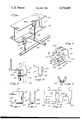
- FIG. 1 is a perspective view showing two clamps of this invention, each supporting a pipe hanger and a pipe.
- FIG. 2 is a side view showing a clamp mounted on a lower flange.
- FIG. 3 is a perspective view of the clamp itself.
- FIG. 4 is a fragmentary cross-sectional view of the clamp showing a threaded hole through a curved section of the end wall.
- FIG. 5 shows an end view of the clamp.
- FIG. 6 shows a side view of another form of the clamp of the invention wherein the flat plate is bent at two locations so that the threaded hole pierces a flat section of the end wall.
- FIG. 7 is an end view of the clamp of FIG. 6.
- FIG. 8 is a top view of the flat metal piece, forming the clamp of FIG. 6, after it has been blanked and drilled, but before it has been bent.
- an I-beam 10 with an upper flange 12 and a lower flange 14 supports a pair of hanger clamps 16.
- a hanger rod 18, attached to a pipe hanger clamp 16 supports a pipe 20.
- the clamp comprises an end wall 22 joining two spaced, vertically extending side members 30 and 40 each having a generally C-shape.
- the side members include an upper pair of horizontally extending support arms 32 and 42 cantilevered from vertical body portions 31 and 41, and a lower pair of side wall portions 35 and 36 extending forwardly from the portions 31 and 41 and being joined to the end wall 22.
- the arms 32 and 42 project generally parallel to each other in direction 1.
- These support arms 32 and 42 have support arm clamping surfaces 33 and 43 for engaging the same side of a supporting member, such as the I-beam flange 14 of FIG. 1.
- the support arm clamping surfaces 33 and 43 have lengths in direction 1, and widths in lateral direction 2.
- the support arms 32 and 42 have a height in directions 3 which is mutually perpendicular with directions 1 and 2.
- the clamp is manufactured so that the width of support arm clamping surfaces 33 and 43 is significantly less than the height of support arms 32 and 42.
- the end wall 22 joining the two side members 30 and 40, has a threaded hole 24 aligned below the support arms 32 and 42, to receive a set screw 52, and has threaded hole 26 below the vertical portions 31 and 41 to receive a pipe hanger rod 18.
- the end wall joins the two side members in such a way that the side members 30 and 40--and therefore the support arm clamping surfaces 33 and 43--are a distance apart. By giving the clamping surfaces a greater lever arm without utilizing a continuous surface, this separation improves the rotational stability of the clamp with respect to the supporting member while minimizing the clamp weight. A single continuous clamp arm will not seat properly if its clamping surface is slightly convex.
- a characteristic of this design is that the plane formed by the support arm clamping surfaces 33 and 43 is between the end wall 22 and the support arms 32 and 42.
- the clamp body is formed by blanking a rectangular piece of metal bar stock 50 indicated by the solid and phantom lines in FIG. 8, into a generally "E"-shaped piece 51 with the height of the middle tine 60 being greater than that of the end tines 61 and 62.
- the piece is subsequently bent around an axis of curvature 53 of the middle tine 60 to the shape shown in FIGS. 2, 3 and 5.
- the clamp has a "U"-shaped edge view, as shown in FIG. 5, wherein the center portion of the middle tine 60 forms the end wall 22 and the remainder of the piece 51 forms "C"-shaped side member as viewed in FIG. 2.
- the end tines 61 and 62 of the E-shaped piece 51 form the support arms 32 and 42, of the C-shaped members 30 and 40, while the arm portions 35 and 36 are formed by portions of the middle tine 60, and the vertical portions of the C-shape side members are formed by the vertical leg of the E-shape.
- the workpiece is denominated as being a piece of bar stock solely to indicate that its thickness is less than its length or width, to facilitate the bending process, and is not used to reflect certain thickness specifications.
- the piece to be blanked could be a plate of 3/16 inch A.I.S.I. 1020 hot rolled steel 43/8 inches long and 2 inches wide.
- a clamp is formed having a 1/2 inch gap between the side members 30 and 40, and having support arm clamping surfaces 33 and 43 with a length four times greater than their width.
- two vertically extending threaded holes 24 and 26 are formed through the end wall 22.
- the threaded hole 24 accommodates a set screw 52 which holds the clamp onto the beam flange, while the threaded hole 26 accommodates a hanger rod 18.
- the axial length of threaded hole 26 is greater than the thickness of the plate from which the clamp is formed. This design is advantageous because a deeper threaded portion increases the thread strength, which supports the load of the pipe.
- FIGS. 6 and 7 is essentially the same as that of FIGS. 1-5 except that the piece 51 cut from the plate 50 is bent twice, once at 90 degrees around the broken bend line 54 in FIG. 8, and also at 90 degrees around the line 55 to create the "U"-shaped clamp shown in FIG. 7, which has a generally flat end wall 22. Nevertheless, the clamp of FIG. 7 might be thought of as being bent approximately around the axis 53a indicated in FIG. 7.
- the threaded holes 24 and 26 through the end wall 22 may be formed either before or after the bending operation.
- the outer edges 34 and 44 of the support arms 32 and 42 are tapered away from the body members 31 and 41, i.e., toward the tip of the support arms 32 and 42.
- This enables the clamp to be inserted between the beam flange 12 in FIG. 1 and roofing that may be supported on the beam.
- the clamp may be inverted so that the set screw 52 engages the top of the beam flange and the support arm clamping surfaces engage the bottom. Such an orientation facilitates the tightening of the set screw 52 since the rod 18 normally does not interfere with the movement of the wrench used for rotating the screw.
- the primary advantage of the clamp of the invention is that it can be formed from a metal plate by a simple cutting and bending operation. Yet the load on the clamp is edgewise to the plate thickness. Thus the torque produced does not tend to unbend the clamp. This design enables the plate to be thinner than it would be if the torque were in the unbending direction.
Abstract
Description
Claims (2)
Priority Applications (1)
| Application Number | Priority Date | Filing Date | Title |
|---|---|---|---|
| US06/533,215 US4570885A (en) | 1983-09-19 | 1983-09-19 | Hanger clamp body and method of forming same |
Applications Claiming Priority (1)
| Application Number | Priority Date | Filing Date | Title |
|---|---|---|---|
| US06/533,215 US4570885A (en) | 1983-09-19 | 1983-09-19 | Hanger clamp body and method of forming same |
Publications (1)
| Publication Number | Publication Date |
|---|---|
| US4570885A true US4570885A (en) | 1986-02-18 |
Family
ID=24124992
Family Applications (1)
| Application Number | Title | Priority Date | Filing Date |
|---|---|---|---|
| US06/533,215 Expired - Lifetime US4570885A (en) | 1983-09-19 | 1983-09-19 | Hanger clamp body and method of forming same |
Country Status (1)
| Country | Link |
|---|---|
| US (1) | US4570885A (en) |
Cited By (41)
| Publication number | Priority date | Publication date | Assignee | Title |
|---|---|---|---|---|
| GB2224307A (en) * | 1988-10-26 | 1990-05-02 | Rankin Macarthur Durnin | Scaffolding clamp |
| DE4328106C1 (en) * | 1993-08-20 | 1995-02-16 | Paul Stange | Pipe-securing means |
| DE29801108U1 (en) * | 1998-01-23 | 1998-03-05 | Alsthom Cge Alcatel | Device for fastening strand-like objects |
| US6021981A (en) * | 1995-09-20 | 2000-02-08 | Leebeeck; Marcel De | Saddle hanger for plastic pipe |
| US6517030B2 (en) | 1999-04-28 | 2003-02-11 | Tolco Incorporated | Sway brace fitting |
| US6520705B2 (en) | 2001-05-10 | 2003-02-18 | Wilson Frank Stasney, Jr. | Clamping assembly |
| US6629678B1 (en) * | 2001-04-27 | 2003-10-07 | Automatic Fire Control, Incorporated | Seismic adapter |
| US6672545B1 (en) | 2000-11-07 | 2004-01-06 | Erico International Corporation | Device for resisting movement of a suspended pipe |
| US6898905B1 (en) * | 2002-07-02 | 2005-05-31 | Automatic Fire Control, Incorporated | Offset beam clamp |
| US20050230582A1 (en) * | 2004-04-14 | 2005-10-20 | Birli Mary E | Threaded rod hanger |
| US7025308B1 (en) * | 2003-04-15 | 2006-04-11 | John Hill | Apparatus for holding and positioning a pipe during installation |
| US20060214073A1 (en) * | 2005-03-22 | 2006-09-28 | Mominee Daniel S | Fabricated heavy duty structural clamp |
| US20070120025A1 (en) * | 2005-11-14 | 2007-05-31 | Wilson Eric J | Structural beam clamp with cast body |
| EP1990547A2 (en) * | 2007-05-09 | 2008-11-12 | Erico International Corporation | Structural beam clamps and connectors |
| US20090065657A1 (en) * | 2003-05-28 | 2009-03-12 | Nibco Inc. | Hanger for fire sprinkler pipe |
| US20090183443A1 (en) * | 2008-01-21 | 2009-07-23 | Osborn Eric C | Universal structural attachment for seismic brace |
| US20100037554A1 (en) * | 2008-08-13 | 2010-02-18 | Oh Michael H-S | Cable locking device and method |
| EP2048375A3 (en) * | 2007-10-05 | 2010-03-17 | Buresuto Kogyo Co. Ltd. | Supporting bracket and nut holder |
| US20100108840A1 (en) * | 2008-10-30 | 2010-05-06 | Oh Michael H-S | Quick threaded rod locking devices and method |
| US7780132B1 (en) | 2007-06-04 | 2010-08-24 | Joe Tomaric | Construction hanger |
| US20100252684A1 (en) * | 2007-11-05 | 2010-10-07 | Andreas Stephan | Fuselage cell structure of an airplane for the simplified installation and attachment of fasteners for fastening conduits |
| US20110017880A1 (en) * | 2008-01-21 | 2011-01-27 | Osborn Eric C | Lateral seismic brace |
| US7887248B2 (en) | 2007-04-20 | 2011-02-15 | Nibco Inc. | Swivel attachment and branch line restraint |
| US20110068232A1 (en) * | 2009-09-18 | 2011-03-24 | Streetman Randy J | Conduit Attachment Device for Use with a Trapeze |
| WO2011150202A1 (en) * | 2010-05-26 | 2011-12-01 | Scot Kennedy | Extrusion tap top beam clamp |
| US20130020447A1 (en) * | 2011-07-20 | 2013-01-24 | Nibco, Inc. | Beam clamp |
| US20130214098A1 (en) * | 2012-02-16 | 2013-08-22 | Greenfield Mfg Co Inc | Top beam clamp |
| EP2434166A3 (en) * | 2010-09-22 | 2014-02-19 | Edgar Kober | Sheet metal girder clamp |
| US8726607B1 (en) * | 2006-11-27 | 2014-05-20 | Automatic Fire Control Incorporated | Sway brace assembly and method of restraining pipe relative to a building structure |
| US8763960B1 (en) | 2009-04-13 | 2014-07-01 | Buckaroos, Inc. | Arcuate saddles with rounded corners |
| US8998155B2 (en) | 2008-10-30 | 2015-04-07 | Erico International Corporation | Quick threaded rod locking devices and method |
| US9188193B2 (en) | 2011-12-06 | 2015-11-17 | Erico International Corporation | Cable locking device |
| JP2017002684A (en) * | 2015-06-16 | 2017-01-05 | 株式会社佐藤型鋼製作所 | Roof frame hanging structure |
| US9746011B2 (en) * | 2015-06-29 | 2017-08-29 | Jiangmen Eurofix Metal And Rubber Products Co., Ltd. | Beam clamp |
| US20170335879A1 (en) * | 2014-11-12 | 2017-11-23 | Illinois Tool Works Inc. | One-piece stud and clip |
| US10054143B2 (en) | 2015-01-19 | 2018-08-21 | James A. Allmon | Connector device for use in connecting elements of bracing systems and the like |
| US10100973B2 (en) | 2016-05-20 | 2018-10-16 | Erico International Corporation | Flange adapter |
| US20200072393A1 (en) * | 2018-08-30 | 2020-03-05 | Anvil International, Llc | Adjustable fitting assembly |
| US10605382B2 (en) | 2018-08-21 | 2020-03-31 | Anvil International, Llc | Fitting for concentrically loading a brace member |
| USD955867S1 (en) * | 2018-10-22 | 2022-06-28 | Li Zhou | Beam clamp |
| US20220316506A1 (en) * | 2019-07-19 | 2022-10-06 | Polyplas International Pty Ltd | A Beam Clamp, and a Mounting Assembly |
Citations (11)
| Publication number | Priority date | Publication date | Assignee | Title |
|---|---|---|---|---|
| US1840216A (en) * | 1931-05-18 | 1932-01-05 | Manuel G Tormo | Conduit support |
| GB660026A (en) * | 1948-11-26 | 1951-10-31 | James Flood | Improvements in cable and pipe supports |
| US2675201A (en) * | 1948-09-22 | 1954-04-13 | Friel Patrick | Beam attachment clamp |
| US2996570A (en) * | 1958-05-09 | 1961-08-15 | Dare Products Inc | Electric insulator mounting clamp |
| US3126182A (en) * | 1964-03-24 | Pipe clamp or hanger | ||
| US3276800A (en) * | 1963-05-07 | 1966-10-04 | Minerallac Electric Company | Beam clip |
| US3321161A (en) * | 1966-06-29 | 1967-05-23 | Metelco Inc | Hanger clamp |
| US3572623A (en) * | 1969-08-06 | 1971-03-30 | Chester A Lapp | Pipe hanger clamp |
| US3874035A (en) * | 1974-06-26 | 1975-04-01 | Fastway Fasteners | Hanger clip |
| US4019705A (en) * | 1972-04-05 | 1977-04-26 | Habuda Sr Blair A | Pipe hanging apparatus |
| US4202083A (en) * | 1978-06-12 | 1980-05-13 | Gutner Kenneth H | Method of making a furniture leveling device |
-
1983
- 1983-09-19 US US06/533,215 patent/US4570885A/en not_active Expired - Lifetime
Patent Citations (11)
| Publication number | Priority date | Publication date | Assignee | Title |
|---|---|---|---|---|
| US3126182A (en) * | 1964-03-24 | Pipe clamp or hanger | ||
| US1840216A (en) * | 1931-05-18 | 1932-01-05 | Manuel G Tormo | Conduit support |
| US2675201A (en) * | 1948-09-22 | 1954-04-13 | Friel Patrick | Beam attachment clamp |
| GB660026A (en) * | 1948-11-26 | 1951-10-31 | James Flood | Improvements in cable and pipe supports |
| US2996570A (en) * | 1958-05-09 | 1961-08-15 | Dare Products Inc | Electric insulator mounting clamp |
| US3276800A (en) * | 1963-05-07 | 1966-10-04 | Minerallac Electric Company | Beam clip |
| US3321161A (en) * | 1966-06-29 | 1967-05-23 | Metelco Inc | Hanger clamp |
| US3572623A (en) * | 1969-08-06 | 1971-03-30 | Chester A Lapp | Pipe hanger clamp |
| US4019705A (en) * | 1972-04-05 | 1977-04-26 | Habuda Sr Blair A | Pipe hanging apparatus |
| US3874035A (en) * | 1974-06-26 | 1975-04-01 | Fastway Fasteners | Hanger clip |
| US4202083A (en) * | 1978-06-12 | 1980-05-13 | Gutner Kenneth H | Method of making a furniture leveling device |
Cited By (86)
| Publication number | Priority date | Publication date | Assignee | Title |
|---|---|---|---|---|
| GB2224307A (en) * | 1988-10-26 | 1990-05-02 | Rankin Macarthur Durnin | Scaffolding clamp |
| DE4328106C1 (en) * | 1993-08-20 | 1995-02-16 | Paul Stange | Pipe-securing means |
| US6021981A (en) * | 1995-09-20 | 2000-02-08 | Leebeeck; Marcel De | Saddle hanger for plastic pipe |
| DE29801108U1 (en) * | 1998-01-23 | 1998-03-05 | Alsthom Cge Alcatel | Device for fastening strand-like objects |
| US7191987B2 (en) * | 1999-04-28 | 2007-03-20 | Tolco Incorporated | Sway brace fitting |
| US20070170317A1 (en) * | 1999-04-28 | 2007-07-26 | Heath Richard W | Sway brace fitting |
| US6708930B2 (en) | 1999-04-28 | 2004-03-23 | Tolco Incorporated | Sway brace fitting |
| US6953174B2 (en) | 1999-04-28 | 2005-10-11 | Tolco Incorporated | Sway brace fitting |
| US8052099B2 (en) | 1999-04-28 | 2011-11-08 | Nibco Inc. | Sway brace fitting |
| US20060022095A1 (en) * | 1999-04-28 | 2006-02-02 | Heath Richard W | Sway brace fitting |
| US7669806B2 (en) * | 1999-04-28 | 2010-03-02 | Nibco Inc. | Sway brace fitting |
| US7441730B2 (en) | 1999-04-28 | 2008-10-28 | Nibco Inc. | Sway brace fitting |
| US6517030B2 (en) | 1999-04-28 | 2003-02-11 | Tolco Incorporated | Sway brace fitting |
| US20100146906A1 (en) * | 1999-04-28 | 2010-06-17 | Nibco Inc. | Sway brace fitting |
| US6672545B1 (en) | 2000-11-07 | 2004-01-06 | Erico International Corporation | Device for resisting movement of a suspended pipe |
| US6629678B1 (en) * | 2001-04-27 | 2003-10-07 | Automatic Fire Control, Incorporated | Seismic adapter |
| US6520705B2 (en) | 2001-05-10 | 2003-02-18 | Wilson Frank Stasney, Jr. | Clamping assembly |
| US6898905B1 (en) * | 2002-07-02 | 2005-05-31 | Automatic Fire Control, Incorporated | Offset beam clamp |
| US7025308B1 (en) * | 2003-04-15 | 2006-04-11 | John Hill | Apparatus for holding and positioning a pipe during installation |
| US20090065657A1 (en) * | 2003-05-28 | 2009-03-12 | Nibco Inc. | Hanger for fire sprinkler pipe |
| US7832248B2 (en) * | 2003-05-28 | 2010-11-16 | Nibco Inc. | Hanger for fire sprinkler pipe |
| US7431252B2 (en) * | 2004-04-14 | 2008-10-07 | Erico International Corporation | Threaded rod hanger |
| US20050230582A1 (en) * | 2004-04-14 | 2005-10-20 | Birli Mary E | Threaded rod hanger |
| US20060214073A1 (en) * | 2005-03-22 | 2006-09-28 | Mominee Daniel S | Fabricated heavy duty structural clamp |
| US20070120025A1 (en) * | 2005-11-14 | 2007-05-31 | Wilson Eric J | Structural beam clamp with cast body |
| US8726607B1 (en) * | 2006-11-27 | 2014-05-20 | Automatic Fire Control Incorporated | Sway brace assembly and method of restraining pipe relative to a building structure |
| US7887248B2 (en) | 2007-04-20 | 2011-02-15 | Nibco Inc. | Swivel attachment and branch line restraint |
| US8714865B2 (en) | 2007-04-20 | 2014-05-06 | Cooper B-Line, Inc. | Swivel attachment and branch line restraint |
| US20110101678A1 (en) * | 2007-04-20 | 2011-05-05 | Nibco Inc. | Swivel attachment and branch line restraint |
| US9464665B2 (en) | 2007-04-20 | 2016-10-11 | Cooper B-Line, Inc. | Swivel attachment and branch line restraint |
| US9879716B2 (en) | 2007-04-20 | 2018-01-30 | Cooper B-Line, Inc. | Swivel attachment and branch line restraint |
| EP1990547A3 (en) * | 2007-05-09 | 2009-09-16 | Erico International Corporation | Structural beam clamps and connectors |
| EP1990547A2 (en) * | 2007-05-09 | 2008-11-12 | Erico International Corporation | Structural beam clamps and connectors |
| US20080277536A1 (en) * | 2007-05-09 | 2008-11-13 | Olle Raymond M | Structural beam clamps and connectors |
| US7780132B1 (en) | 2007-06-04 | 2010-08-24 | Joe Tomaric | Construction hanger |
| EP2048375A3 (en) * | 2007-10-05 | 2010-03-17 | Buresuto Kogyo Co. Ltd. | Supporting bracket and nut holder |
| US20100252684A1 (en) * | 2007-11-05 | 2010-10-07 | Andreas Stephan | Fuselage cell structure of an airplane for the simplified installation and attachment of fasteners for fastening conduits |
| US8408496B2 (en) * | 2007-11-05 | 2013-04-02 | Airbus Operations Gmbh | Fuselage cell structure of an airplane for the simplified installation and attachment of fasteners for fastening conduits |
| US8100369B2 (en) | 2008-01-21 | 2012-01-24 | Erico International Corporation | I-beam seismic sway brace clamp |
| US7971838B2 (en) | 2008-01-21 | 2011-07-05 | Erico International Corporation | Flange-engaging clamp |
| US20110017880A1 (en) * | 2008-01-21 | 2011-01-27 | Osborn Eric C | Lateral seismic brace |
| US20090183443A1 (en) * | 2008-01-21 | 2009-07-23 | Osborn Eric C | Universal structural attachment for seismic brace |
| US20090183463A1 (en) * | 2008-01-21 | 2009-07-23 | Eric C Osborn | Lateral seismic brace |
| US20090184222A1 (en) * | 2008-01-21 | 2009-07-23 | Osborn Eric C | Flange-engaging clamp |
| US8353486B2 (en) | 2008-01-21 | 2013-01-15 | Erico International Corporation | Lateral seismic brace |
| US8353143B2 (en) | 2008-01-21 | 2013-01-15 | Erico International Corporation | Lateral seismic brace |
| US20090183462A1 (en) * | 2008-01-21 | 2009-07-23 | Osborn Eric C | I-beam seismic sway brace clamp |
| US20100037554A1 (en) * | 2008-08-13 | 2010-02-18 | Oh Michael H-S | Cable locking device and method |
| US10578137B2 (en) | 2008-10-30 | 2020-03-03 | Erico International Corporation | Quick-threaded rod locking device and method |
| US8434725B2 (en) | 2008-10-30 | 2013-05-07 | Erico International Corporation | Quick threaded rod locking devices and method |
| US11047409B2 (en) | 2008-10-30 | 2021-06-29 | Erico International Corporation | Quick-threaded rod locking device and method |
| US11572905B2 (en) | 2008-10-30 | 2023-02-07 | Erico International Corporation | Quick-threaded rod locking device and method |
| US8998155B2 (en) | 2008-10-30 | 2015-04-07 | Erico International Corporation | Quick threaded rod locking devices and method |
| US8132767B2 (en) | 2008-10-30 | 2012-03-13 | Erico International Corporation | Quick threaded rod locking devices and method |
| US20100108840A1 (en) * | 2008-10-30 | 2010-05-06 | Oh Michael H-S | Quick threaded rod locking devices and method |
| US9303676B2 (en) | 2008-10-30 | 2016-04-05 | Erico International Corporation | Quick-threaded rod locking device and method |
| US11773884B2 (en) | 2008-10-30 | 2023-10-03 | Erico International Corporation | Quick-threaded rod locking device and method |
| US9915277B2 (en) | 2008-10-30 | 2018-03-13 | Erico International Corporation | Quick-threaded rod locking device and method |
| US8915110B1 (en) * | 2009-04-13 | 2014-12-23 | Buckaroos, Inc. | Arcuate saddles with rounded corners |
| US8763960B1 (en) | 2009-04-13 | 2014-07-01 | Buckaroos, Inc. | Arcuate saddles with rounded corners |
| US8857771B2 (en) * | 2009-09-18 | 2014-10-14 | Randy J. Streetman | Conduit attachment device for use with a trapeze |
| US20110068232A1 (en) * | 2009-09-18 | 2011-03-24 | Streetman Randy J | Conduit Attachment Device for Use with a Trapeze |
| WO2011150202A1 (en) * | 2010-05-26 | 2011-12-01 | Scot Kennedy | Extrusion tap top beam clamp |
| EP2434166A3 (en) * | 2010-09-22 | 2014-02-19 | Edgar Kober | Sheet metal girder clamp |
| US20130020447A1 (en) * | 2011-07-20 | 2013-01-24 | Nibco, Inc. | Beam clamp |
| US9188193B2 (en) | 2011-12-06 | 2015-11-17 | Erico International Corporation | Cable locking device |
| US20130214098A1 (en) * | 2012-02-16 | 2013-08-22 | Greenfield Mfg Co Inc | Top beam clamp |
| US8882056B2 (en) * | 2012-02-16 | 2014-11-11 | Greenfield Mfg. Co. Inc. | Top beam clamp |
| US20170335879A1 (en) * | 2014-11-12 | 2017-11-23 | Illinois Tool Works Inc. | One-piece stud and clip |
| US11117176B2 (en) * | 2014-11-12 | 2021-09-14 | Illinois Tool Works Inc. | One-piece stud and clip |
| US10054143B2 (en) | 2015-01-19 | 2018-08-21 | James A. Allmon | Connector device for use in connecting elements of bracing systems and the like |
| JP2017002684A (en) * | 2015-06-16 | 2017-01-05 | 株式会社佐藤型鋼製作所 | Roof frame hanging structure |
| US9746011B2 (en) * | 2015-06-29 | 2017-08-29 | Jiangmen Eurofix Metal And Rubber Products Co., Ltd. | Beam clamp |
| US10100973B2 (en) | 2016-05-20 | 2018-10-16 | Erico International Corporation | Flange adapter |
| US10605382B2 (en) | 2018-08-21 | 2020-03-31 | Anvil International, Llc | Fitting for concentrically loading a brace member |
| US11060638B2 (en) | 2018-08-21 | 2021-07-13 | ASC Engineered Solutions, LLC | Fitting for brace member |
| US11703150B2 (en) | 2018-08-21 | 2023-07-18 | ASC Engineered Solutions, LLC | Fitting for brace member |
| US11028945B2 (en) * | 2018-08-30 | 2021-06-08 | Anvil International, Llc | Adjustable fitting assembly |
| US10816108B2 (en) * | 2018-08-30 | 2020-10-27 | Anvil International, Llc | Adjustable fitting assembly |
| US11421802B2 (en) | 2018-08-30 | 2022-08-23 | ASC Engineered Solutions, LLC | Adjustable fitting assembly |
| US20200284378A1 (en) * | 2018-08-30 | 2020-09-10 | Anvil International, Llc | Adjustable fitting assembly |
| US20200072393A1 (en) * | 2018-08-30 | 2020-03-05 | Anvil International, Llc | Adjustable fitting assembly |
| US11808390B2 (en) | 2018-08-30 | 2023-11-07 | ASC Engineered Solutions, LLC | Adjustable fitting assembly |
| USD955867S1 (en) * | 2018-10-22 | 2022-06-28 | Li Zhou | Beam clamp |
| US20220316506A1 (en) * | 2019-07-19 | 2022-10-06 | Polyplas International Pty Ltd | A Beam Clamp, and a Mounting Assembly |
| EP3999763A4 (en) * | 2019-07-19 | 2023-07-19 | Polyplas International Pty Ltd. | A beam clamp, and a mounting assembly |
Similar Documents
| Publication | Publication Date | Title |
|---|---|---|
| US4570885A (en) | Hanger clamp body and method of forming same | |
| US5947424A (en) | Pipe support assembly with retaining strap | |
| US8882056B2 (en) | Top beam clamp | |
| US9982837B2 (en) | Fitting including clip for channel framing | |
| US20180266109A1 (en) | Bridge clip | |
| US20020100239A1 (en) | Wire tie and hardware system | |
| US8857771B2 (en) | Conduit attachment device for use with a trapeze | |
| US20170009451A1 (en) | Beam clip with teeth | |
| US4708554A (en) | Strut | |
| US4479625A (en) | Conduit hanger | |
| US5312079A (en) | Universal C-clamp for stage accessories | |
| US3748808A (en) | Wire furring hangers | |
| US5259165A (en) | Supporting metal fittings for double beams | |
| US5149040A (en) | Side beam pipe hanger and method of making | |
| CN219863315U (en) | Purline connecting device for steel structure house | |
| GB2228955A (en) | Joist hangers | |
| GB2140118A (en) | Slotted insert and nut assembly | |
| US10563401B2 (en) | Bridge clip | |
| JP3177740B1 (en) | Bracket for additional child girder | |
| US7806375B1 (en) | Retaining key | |
| JP2823509B2 (en) | End connection structure of channel for ceiling base | |
| WO1990010765A1 (en) | Joist hangers | |
| CN211371468U (en) | A synthesize a gallows for assembled steel construction factory building I-shaped steel beam | |
| US6749359B1 (en) | Seismic suspension system | |
| JP2710651B2 (en) | Wall panel mounting structure |
Legal Events
| Date | Code | Title | Description |
|---|---|---|---|
| AS | Assignment |
Owner name: TOLCO, INCORPORATED 601 WEST LAMBERT BREA, CA 926 Free format text: ASSIGNMENT OF ASSIGNORS INTEREST.;ASSIGNOR:HEATH, RICHARD W.;REEL/FRAME:004175/0649 Effective date: 19830908 Owner name: TOLCO, INCORPORATED, A CA CORP., CALIFORNIA Free format text: ASSIGNMENT OF ASSIGNORS INTEREST;ASSIGNOR:HEATH, RICHARD W.;REEL/FRAME:004175/0649 Effective date: 19830908 |
|
| STCF | Information on status: patent grant |
Free format text: PATENTED CASE |
|
| FEPP | Fee payment procedure |
Free format text: PAYOR NUMBER ASSIGNED (ORIGINAL EVENT CODE: ASPN); ENTITY STATUS OF PATENT OWNER: SMALL ENTITY |
|
| FPAY | Fee payment |
Year of fee payment: 4 |
|
| FPAY | Fee payment |
Year of fee payment: 8 |
|
| FPAY | Fee payment |
Year of fee payment: 12 |
|
| REMI | Maintenance fee reminder mailed | ||
| AS | Assignment |
Owner name: NIBCO INC., INDIANA Free format text: ASSIGNMENT OF ASSIGNORS INTEREST;ASSIGNOR:TOLCO, INC.;REEL/FRAME:016216/0041 Effective date: 20020603 |