US4569646A - Supercharger carry-over venting means - Google Patents

Supercharger carry-over venting means Download PDF

Info

Publication number
US4569646A
US4569646A US06/647,074 US64707484A US4569646A US 4569646 A US4569646 A US 4569646A US 64707484 A US64707484 A US 64707484A US 4569646 A US4569646 A US 4569646A
Authority
US
United States
Prior art keywords
lobes
volumes
blower
rotor
volume
Prior art date
Legal status (The legal status is an assumption and is not a legal conclusion. Google has not performed a legal analysis and makes no representation as to the accuracy of the status listed.)
Expired - Lifetime
Application number
US06/647,074
Inventor
Raymond A. Soeters, Jr.
Current Assignee (The listed assignees may be inaccurate. Google has not performed a legal analysis and makes no representation or warranty as to the accuracy of the list.)
Eaton Corp
Original Assignee
Eaton Corp
Priority date (The priority date is an assumption and is not a legal conclusion. Google has not performed a legal analysis and makes no representation as to the accuracy of the date listed.)
Filing date
Publication date
Application filed by Eaton Corp filed Critical Eaton Corp
Priority to US06/647,074 priority Critical patent/US4569646A/en
Assigned to EATON CORPORATION A CORP. OF OH reassignment EATON CORPORATION A CORP. OF OH ASSIGNMENT OF ASSIGNORS INTEREST. Assignors: SOETERS, RAYMOND A. JR
Priority to DE8585306199T priority patent/DE3576388D1/en
Priority to EP85306199A priority patent/EP0176268B1/en
Priority to JP60195702A priority patent/JPS6181593A/en
Application granted granted Critical
Publication of US4569646A publication Critical patent/US4569646A/en
Anticipated expiration legal-status Critical
Expired - Lifetime legal-status Critical Current

Links

Images

Classifications

    • FMECHANICAL ENGINEERING; LIGHTING; HEATING; WEAPONS; BLASTING
    • F04POSITIVE - DISPLACEMENT MACHINES FOR LIQUIDS; PUMPS FOR LIQUIDS OR ELASTIC FLUIDS
    • F04CROTARY-PISTON, OR OSCILLATING-PISTON, POSITIVE-DISPLACEMENT MACHINES FOR LIQUIDS; ROTARY-PISTON, OR OSCILLATING-PISTON, POSITIVE-DISPLACEMENT PUMPS
    • F04C18/00Rotary-piston pumps specially adapted for elastic fluids
    • F04C18/08Rotary-piston pumps specially adapted for elastic fluids of intermeshing-engagement type, i.e. with engagement of co-operating members similar to that of toothed gearing
    • F04C18/082Details specially related to intermeshing engagement type pumps
    • F04C18/088Elements in the toothed wheels or the carter for relieving the pressure of fluid imprisoned in the zones of engagement
    • FMECHANICAL ENGINEERING; LIGHTING; HEATING; WEAPONS; BLASTING
    • F04POSITIVE - DISPLACEMENT MACHINES FOR LIQUIDS; PUMPS FOR LIQUIDS OR ELASTIC FLUIDS
    • F04CROTARY-PISTON, OR OSCILLATING-PISTON, POSITIVE-DISPLACEMENT MACHINES FOR LIQUIDS; ROTARY-PISTON, OR OSCILLATING-PISTON, POSITIVE-DISPLACEMENT PUMPS
    • F04C18/00Rotary-piston pumps specially adapted for elastic fluids
    • F04C18/08Rotary-piston pumps specially adapted for elastic fluids of intermeshing-engagement type, i.e. with engagement of co-operating members similar to that of toothed gearing
    • F04C18/12Rotary-piston pumps specially adapted for elastic fluids of intermeshing-engagement type, i.e. with engagement of co-operating members similar to that of toothed gearing of other than internal-axis type
    • F04C18/14Rotary-piston pumps specially adapted for elastic fluids of intermeshing-engagement type, i.e. with engagement of co-operating members similar to that of toothed gearing of other than internal-axis type with toothed rotary pistons
    • F04C18/16Rotary-piston pumps specially adapted for elastic fluids of intermeshing-engagement type, i.e. with engagement of co-operating members similar to that of toothed gearing of other than internal-axis type with toothed rotary pistons with helical teeth, e.g. chevron-shaped, screw type

Definitions

  • This invention relates to rotary compressors or blowers, particularly to blowers of the backflow type. More specifically, the present invention relates to improvements in efficiency and to reducing airborne noise associated with Roots-type blowers emploed as superchargers for internal combustion engines.
  • Rotary blowers particularly Roots-type blowers are characterized by noisy operation.
  • the blower noise may be roughly classified into two groups: solid borne noise caused by rotation of timing gears and rotor shaft bearings subjected to fluctuating loads, and fluid borne noise caused by fluid flow characteristics such as rapid changes in fluid velocity. Fluctuating fluid flow contributes to both solid and fluid borne noise.
  • Roots-type blowers are similar to gear-type pumps in that both employ toothed or lobed rotors meshingly disposed in transversely overlapping cylindrical chambers. Top lands of the lobes sealingly cooperate with the inner surfaces of the cylindrical chambers to trap and transfer volumes of fluid between adjacent lobes on each rotor. Roots-type blowers are used almost exclusively to pump or transfer volumes of compressible fluids, such as air, from an inlet receiver chamber to an outlet receiver chamber. Normally, the inlet chamber continuously communicates with an inlet port and the outlet chamber continuously communicates with an outlet port. The inlet and outlet ports often have a transverse width nominally equal to the transverse distance between the axes of the rotors.
  • each receiver chamber volume is defined by the inner boundary of the associated port, the meshing interface of the lobes, and sealing lines between the top lands of the lobes and cylindrical wall surfaces.
  • the inlet receiver chamber expands and contracts between maximum and minimum volumes while the outlet receiver chamber contracts and expands between like minimum and maximum volumes.
  • transfer volumes are moved to the outlet receiver chamber without compression of the air therein by mechanical reduction of the transfer volume size. If outlet port air pressure is greater than the air pressure in the transfer volume, outlet port air rushes or backflows into the volumes as they become exposed to or merged into the outlet receiver chamber. Backflow continues until pressure equalization is reached.
  • backflow air and rate of backflow are, of course, a function of pressure differential.
  • Backflow into one transfer volume which ceases before backflow starts into the next transfer volume, or which varies in rate, is said to be cyclic and is a known major source of airborne noise.
  • Nonuniform displacement is caused by cyclic variations in the rate of volume change of the receiver chamber due to meshing geometry of the lobes and due to trapped volumes between the meshing lobes.
  • first and second trapped volumes are formed.
  • the first trapped volumes contain outlet port or receiver chamber air which is abruptly removed from the outlet receiver chamber as the lobes move into mesh and abruptly returned or carried back to the inlet receiver chamber as the lobes move out of mesh.
  • the trapped volumes are further sources of airborne noise and inefficiency for both straight and helical lobed rotors.
  • both the first and second trapped volumes are formed along the entire length of the lobes, whereas with helical lobed rotors, the trapped volumes are formed along only a portion of the length of the lobes with a resulting decrease in the degrading effects on noise and efficiency.
  • the first trapped volumes contain outlet port air and decrease in size from a maximum to a minimum, with a resulting compressing of the fluid therein.
  • the second trapped volumes are substantially void of fluid and increase in size from a minimum to a maximum with a resulting vacuum tending expansion. The resulting compression of air in the first trapped volumes, which are subsequently expanded back into the inlet port, and expansion of the second trapped volumes are sources of airborne noise and inefficiencies.
  • Nonuniform displacement, due to trapped volumes, is of little or no concern with respect to the Hallett blower since the lobe profiles therein inherently minimize the size of the trapped volumes.
  • lobe profiles in combination with the the helical twist, can be difficult to accurately manufacture and accurately time with respect to each other when the blowers are assembled.
  • Hallett also addressed the backflow problem and proposed reducing the initial rate of backflow to reduce the instantaneous magnitude of the backflow pulses. This was done by a mismatched or rectangular shaped outlet port having two sides parallel to the rotor axes and, therefore, skewed relative to the traversing top lands of the helical lobes.
  • U.S. Pat. No. 2,463,080 to Beier discloses a related backflow solution for a straight lobe blower by employing a triangular outlet port having two sides skewed relative to the rotor axes and, therefore, mismatched relative to the traversing lands of the straight lobes.
  • the Weatherston blower provides preflow of outlet receiver chamber air to the transfer volumes via circumferentially disposed, arcuate channels or slots formed in the inner surfaces of the cylindrical walls which sealingly cooperate with the top lands of the rotor lobes.
  • the top lands and channels cooperate to define orifices for directing outlet receiver chamber air into the transfer volumes.
  • the arc or setback length of the channels determines the beginning of preflow.
  • Weatherston suggests the use of additional channels of lesser setback length may be employed to hold the rate of preflow relatively constant as pressure in the transfer volumes increases.
  • the Weatherston preflow arrangement which is analogous to backflow, is believed theoretically capable of providing a relatively constant preflow rate for predetermined blower speeds and differential pressures. However, to obtain relatively constant preflow, several channels of different setback length would be necessary. Further, accurate and consistent forming of the several channels on the interior surface of the cylindrical walls is, at best, an added manufacturing cost.
  • U.S. Pat. No. 2,578,196 to Montelius discloses an arrangement for porting air in first trapped volumes back to the outlet port.
  • the objective of the Montelius arrangement is to prevent or reduce pumping losses associated with the first trapped volumes and offers no solution to noise and inefficiencies associated with expansion of the second trapped volumes.
  • the arrangement requires the addition of a plate fixed to an end of one rotor to prevent direct communication between the inlet and outlet ports.
  • the plate in addition to being an added expense, precludes implementation of the Montelius arrangement in Roots-type blowers wherein two pairs of transversely spaced apart trapped volumes are formed in the root areas of both rotors.
  • An object of the present invention is to provide a rotary blower of the backflow type for compressible fluids which is relatively free of airborne noises due to compression and expansion of trapped volumes.
  • Another object of the present invention is to provide a rotary blower of the backflow type for compressible fluids wherein nonuniform displacement, due to meshing geometry and trapped volumes, is substantially eliminated, and wherein airborne noise and inefficiencies associated with compression and expansion of trapped volumes is greatly reduced.
  • a rotary blower of the backflow type includes a housing defining first and second parallel, transversely overlapping, cylindrical chambers having cylindrical and end wall surfaces; first and second meshed lobed rotors respectively disposed in the first and second chambers for transferring volumes of compressible low-pressure inlet port fluid via spaces between adjacent unmeshed lobes of each rotor to high-pressure outlet port fluid, the rotors and lobes sealingly cooperate with the wall surfaces, and the meshing lobes sealingly cooperate with each other; first and second volumes defined by spaces between the meshing lobes, the first volume isolated from the second volume and the ports by the sealing cooperation during at least a portion of each mesh of the lobes, and the first volume containing outlet port fluid and decreasing in size from a maximum to a minimum while the second volume increases in size from a minimum to a a maximum.
  • the improvement comprises first and second passages formed in at least one end wall of the chamber for alternately communicating alternately formed first volumes with the
  • Roots-type blower intended for use as a supercharger is illustrated in the accompanying drawings in which:
  • FIG. 1 is a side elevational view of the Roots-type blower
  • FIG. 2 is a schematic sectional view of the blower looking along line 2--2 of FIG. 1;
  • FIG. 3 is a bottom view of a portion of the blower looking in the direction of arrow 3 in FIG. 1;
  • FIG. 4 is a top view of a portion of the blower looking along line 4--4 of FIG. 1;
  • FIG. 5 is a graph illustrating operational characteristics of the blower
  • FIGS. 6-8 are reduced views of the blower section of FIG. 2 with the meshing relationships of the rotors therein varied;
  • FIGS. 9-14 are reduced schematic views of the left end of rotors shown in FIGS. 2 and 6-8 and looking along line 9--9 of FIG. 1;
  • FIG. 15 is a somewhat schematic sectional view of the blower housing looking in the opposite direction of the arrows along line 9--9 of FIG. 1.
  • FIG. 16 is a reduced schematic view of the right end of the rotors looking along line 16--16 of FIG. 1.
  • FIGS. 1-4 illustrate a rotary pump or blower 10 of the Roots-type.
  • blowers are used almost exclusively to pump or transfer volumes of compressible fluid, such as air, from an inlet port to an outlet port without compressing the transfer volumes prior to exposure to the outlet port.
  • the rotors operate somewhat like gear-type pumps, i.e., as the rotor teeth or lobes move out of mesh, air flows into volumes or spaces defined by adjacent lobes on each rotor. The air in the volumes is then trapped therein at substantially inlet pressure when the top lands of the trailing lobe of each transfer volume moves into a sealing relation with the cylindrical wall surfaces of the associated chamber.
  • the volumes of air are transferred or exposed to outlet air when the top land of the leading lobe of each volume moves out of sealing relation with the cylindrical wall surfaces by traversing the boundary of the outlet port. If the volume of the transfer volumes remains constant during the trip from inlet to outlet, the air therein remains at inlet pressure, i.e., transfer volume air pressure remains constant if the top lands of the leading lobes traverse the outlet port boundary before the volumes are squeezed by virtue of remeshing of the lobes. Hence, if air pressure at the discharge port is greater than inlet port pressure, outlet port air rushes or backflows into the transfer volumes as the top lands of the leading lobes traverse the outlet port boundary.
  • Blower 10 includes a housing assembly 12, a pair of lobed rotors 14, 16, and an input drive pulley 18.
  • Housing assembly 12 as viewed in FIG. 1, includes a center section 20, left and right end sections 22, 24 secured to opposite ends of the center section by a plurality of bolts 26, and an outlet duct member 28 secured to the center section by a plurality of unshown bolts.
  • the housing assembly and rotors are preferably formed from a lightweight material such as aluminum.
  • the center section and end 24 define a pair of generally cylindrical working chambers 32, 34 circumferentially defined by cylindrical wall portions or surfaces 20a, 20b, an end wall surface indicated by phantom line 20c in FIG. 1, and an end wall surface 24a. Chambers 32, 34 traversely overlap or intersect at cusps 20d, 20e, as seen in FIG. 2. Openings 36, 38 in the bottom and top of center section 20 respectively define the transverse and longitudinal boundaries of inlet and outlet ports.
  • Rotors 14, 16 respectively include three circumferentially spaced apart helical teeth or lobes 14a, 14b, 14c and 16a, 16b, 16c of modified involute profile with an end-to-end twist of 60°.
  • the lobes or teeth mesh and preferably do not touch.
  • a sealing interface between meshing lobes 14c, 16c is represented by point M in FIG. 2.
  • Interface or point M moves along the lobe profiles as the lobes progress through each mesh cycle and may be defined in several places as shown in FIG. 7.
  • the lobes also include top lands 14d, 14e, 14f, and 16d, 16e, 16f.
  • Rotors 14, 16 are respectively mounted for rotation in cylindrical chambers 32, 34 about axes coincident with the longitudinally extending, transversely spaced apart, parallel axes of the cylindrical chambers. Such mountings are well-known in the art. Hence, it should suffice to say that unshown shaft ends extending from and fixed to the rotors are supported by unshown bearings carried by end wall 20c and end section 24. Bearings for carrying the shaft ends extending rightwardly into end section 24 are carried by outwardly projecting bosses 24b, 24c.
  • the rotors may be mounted and timed as shown in U.S. Pat.
  • Rotor 16 is directly driven by pulley 18 which is fixed to the left end of a shaft 40.
  • Shaft 40 is either connected to or an extension of the shaft end extending from the left end of rotor 16.
  • Rotor 14 is driven in a conventional manner by unshown timing gears fixed to the shaft ends extending from the left ends of the rotors.
  • the timing gears are of the substantially no backlash type and are disposed in a chamber defined by a portion 22a of end section 22.
  • the rotors as previously mentioned herein have three circumferentially spaced lobes of modified involute profile with an end-to-end helical twist of 60°.
  • Rotors with other than three lobes, with different profiles and with different twist angles may be used to practice certain aspects or features of the inventions disclosed herein.
  • the lobes are preferably provided with a helical twist from end-to-end which is substantially equal to the relation 360°/2n, where n equals the number of lobes per rotor.
  • involute profiles are also preferred since such profiles are more readily and accurately formed than most other profiles; this is particularly true for helically twisted lobes.
  • involute profiles are preferred since they have been more readily and accurately timed during supercharger assembly.
  • inlet receiver chamber 36a is defined by portions of the cylindrical wall surfaces disposed between top lands 14e, 16e and the lobe surfaces extending from the top lands to the interface M of meshing lobes 14c, 16c.
  • Interface M defines the point or points of closest contact between the meshing lobes.
  • outlet receiver chamber 38a is defined by portions of the cylindrical wall surfaces disposed between top lands 14d, 16d and the lobe surfaces extending from the top lands to the interface M of meshing lobes 14c, 16c.
  • transfer volume 32a is defined by adjacent lobes 14a, 14b and the portion of cylindrical wall surfaces 20a disposed between top lands 14d, 14e.
  • transfer volume 34a is defined by adjacent lobes 16a, 16b and the portion of cylindrical wall surface 20b disposed between top lands 16d, 16e. As the rotors turn, transfer volumes 32a, 34a are reformed between subsequent pairs of adjacent lobes.
  • Inlet port 36 is provided with an opening shaped substantially like an isosceles trapezoid by wall surfaces 20f, 20g, 20h, 20i defined by housing section 20.
  • Wall surfaces 20f, 20h define the longitudinal extent of the port and wall surfaces 20g, 20i define the transverse boundaries or extent of the port.
  • the isosceles sides or wall surfaces 20g, 20i are matched or substantially parallel to the traversing top lands of the lobes.
  • the top lands of the helically twisted lobes in both FIGS. 3 and 4 are schematically illustrated as being straight for simplicity herein. As viewed in FIGS. 3 and 4, such lands actually have a curvature.
  • Wall surfaces 20g, 20i may be curved to more closely conform to the helical twist of the top lands.
  • Outlet port 38 is provided with a somewhat T-shaped opening by wall surfaces 20m, 20n, 20p, 20r, 20s, 20t defined by housing section 20.
  • the top surface of housing 20 includes a recess 20w to provide an increased flow area for outlet duct 28.
  • Wall surfaces 20m, 20r are parallel and define the longitudinal extent of the port.
  • Wall surfaces 20p, 20s and their projections to surface 20m define the transverse boundaries or extent of the port for outflow of most air from the blower.
  • Wall surfaces 20p, 20s are also parallel and may be spaced farther apart than shown herein if additional outlet port area is needed to prevent a pressure drop or back pressure across the outlet port.
  • Diagonal wall surfaces 20n, 20t which converge with transverse extensions of wall surface 20m at apexes 20x, 20z, define expanding orifices 42, 44 in combination with the traversing top lands of the lobes.
  • the expanding orifices control the rate of back flow air into the transfer volumes.
  • Orifices 42, 44 are designed to expand at a rate operative to maintain a substantially constant backflow rate of air into the transfer volumes when the blower operates at predetermined speed and differential pressure relationships.
  • Apexes 20x, 20z are respectively spaced approximately 60 rotational degrees from surfaces 20p, 20s and are alternately traversed by the top lands of the associated lobes.
  • inlet port wall surfaces 20g, 20i and the apexes allow the top lands of the trailing lobes of each transfer volume to move into sealing relation with the cylindrical wall surfaces before backflow starts and allows a full 60° rotation of the lobes for backflow.
  • Apexes 20x, 20z may be positioned to allow backflow slightly before the top lands of the trailing lobes of each transfer volume move into sealing relation with cylindrical wall surfaces 20a, 20b, thereby providing a slight overlap between the beginning and ending of backflow to ensure a smoother and continuous transition of backflow from one transfer volume to the next.
  • curves S and H illustrate cyclic variations in volumetric displacement over 60° periods of rotor rotation.
  • the variations are illustrated herein in terms of degrees of rotation but may be illustrated in terms of time.
  • Such cyclic variations are due to the meshing geometry of the rotor lobes which effect the rate of change of volume of the outlet receiver chamber 38a. Since the inlet and outlet receiver chamber volumes vary at substantially the same rate and merely inverse to each other, the curves for outlet receiver chamber 38a should suffice to illustrate the rate of volume change for both chambers.
  • Curve S illustrates the rate of change for a blower having three straight lobes of modified involute profile per rotor and curve H for a blower having three 60° helical twist lobes of modified involute profile per rotor.
  • the absolute value of rate-of-change is approximately 7% of theoretical displacement for straight lobe rotors while there is no variation in the rate of displacement for 60° helical lobes.
  • the rate of volume change or uniform displacement for both straight and helical lobes is due in part to the meshing geometry of the lobes.
  • the meshing relationship of the lobes is the same along the entire length of the lobes, i.e., the meshing relationship at any cross section or incremental volume along the meshing lobes is the same.
  • interface or point M of FIG. 2 is the same along the entire length of the meshing lobes, and a line through the points is straight and parallel to the rotor axis.
  • a rate of volume change, due to meshing geometry is the same and additive for all incremental volumes along the entire length of the meshing lobes.
  • Volumes of fluid trapped between meshing lobes are another cause or source affecting the rate of cyclic volume change of the receiver chambers.
  • the trapped volumes are abruptly removed from the outlet receiver chamber and abruptly returned or carried back to the inlet receiver chamber.
  • the trapped volumes also reduce blower displacement and pumping efficiency.
  • Curves ST and HT in the graph of FIG. 5 respectively illustrate the rate of cyclic volume change of the outlet receiver chamber due to trapped volumes for straight and 60° helical twist lobes. As may be seen, the rate of volume change, as a percentage of theoretical displacement due to trapped volumes, is approximately 4.5 times greater for straight lobes.
  • the total rate of volume change of the receiver chamber is obtained by adding the associated curves for meshing geometry and trapped volume together.
  • FIGS. 6 and 7 therein is shown areas trapped between adjacent lobes 14a, 14c and 16c.
  • the areas may be thought of as incremental volumes when they have a small depth.
  • the area for the meshing relationship of FIG. 6 represents a maximum incremental volume TV 1 .
  • incremental volume TV 1 decreases in size while a second incremental volume TV 2 is formed which increases in size.
  • each maximum incremental volume TV 1 is formed along the entire length of the meshing lobes at substantially the same instant.
  • each incremental volume TV 2 is formed along the entire length of the meshing lobes at substantially the same instant.
  • the sums ⁇ TV 1 and ⁇ TV 2 of the incremental volumes define or form trapped volumes.
  • ⁇ TV 1 and ⁇ TV 2 contribute to airborne noise and reduced blower efficiency. Both, particularly ⁇ TV 1 , cause substantial rates of volume change as illustrated in the graph of FIG. 5.
  • the carryback of fluid in ⁇ TV 1 and the respective decrease and increase in the size of ⁇ TV 1 and ⁇ TV 2 directly reduce blower efficiency.
  • Helical lobes greatly reduce the size of ⁇ TV 1 and ⁇ TV 2 ; this may be illustrated with reference to FIG. 6, which is a sectioned view of the rightward end of the rotors.
  • FIG. 6 is a sectioned view of the rightward end of the rotors.
  • incremental volume TV 1 at the rightward end of meshing lobes 14a, 14c and 16c is not trapped and subsequent incremental volumes TV 1 from right-to-left are not trapped until the leftward end of lobes 14a, 14c and 16c move into the same meshing relationship.
  • For 60° twist lobes this does not occur until the rotors turn an additional 60°.
  • each successive incremental volume TV 1 from right-to-left decreases in size while still in communication with the outlet receiver chamber.
  • the number of trapped incremental volumes TV 1 is greatly reduced. Further, the total volume of this number of trapped incremental volumes is less than the total volume of a comparable number of straight lobe incremental volumes since trapped incremental volumes with helical lobes vary in cross-sectional area from a minimum to a maximum.
  • the number of trapped incremental volumes TV 2 and their total volume is the same as described for incremental volumes TV 1 . However, their formation sequence occurs in the reverse order, i.e., when incremental volume TV 2 starts to form and expand at the right end of the lobes, it and subsequent incremental volumes TV 2 are trapped until the right end of the lobes moves to the meshing relationship shown in FIG. 8; from thereon all incremental volumes TV 2 are in constant communication with the inlet receiver chamber.
  • FIGS. 9-14 therein is shown a meshing cycle viewed from the left end of helical meshing lobes 14 and 16b, 16c with the projections of two passages or channels 46, 48 superimposed thereon.
  • the channels as shown in FIG. 15, are formed in the surface of left end wall 20c and provide communication between incremental volumes TV 1 and TV 2 as they respectively decrease and increase in size. Bearings which would normally be seen in bores 61, 63 in end wall 20c are omitted for simplicity.
  • the channels may be straight, but are preferably formed with arcuate sides having their respective centers of radius located at the axes of rotation 50, 52 of the rotors.
  • the side walls formed by the smaller radii are substantially the same as the root diameters or root radii 54, 56 of the lobes. Both channels are approximately 30° in arc length and are centered about an unshown line extended between the axes of rotation. Keeping in mind that the rotors are being viewed from the left end in FIGS. 9-14, when the left end of lobe 14c is in the position shown in FIG. 9, i.e., in sealing relation with lobe 16b and just prior to moving into a sealing relation with lobe 16c as shown in FIG. 10, the right end of lobe 14c has already moved out of sealing relation with the lobe 16b as shown in FIG. 2.
  • FIGS. 10-13 illustrate incremental volume TV 1 and trapped incremental volume ⁇ TV 1 decreasing in size from a maximum to a minimum while incremental volume TV 2 forms and increases in size from a minimum to a maximum.
  • TV 1 and TV 2 are in communication with each other via arcuate channel 46 and TV 2 is in continuous communication with inlet receiver chamber 36a. Hence, compression of the air in ⁇ TV 1 is prevented by venting to the inlet receiver chamber.
  • FIG. 16 schematically illustrates a meshing relationship of lobes 14c and 16a, 16c viewed from the right end of the rotors with projections of two passages or channels 58, 60 superimposed thereon.
  • channels 58, 60 are formed in the surface of right end wall 24a.
  • Channels 58, 60 provide communication between incremental volumes TV 1 and TV 2 as they respectively decrease and increase in size.
  • Channels 58, 60 are preferably positioned and sized the same as channels 46, 48.

Landscapes

  • Engineering & Computer Science (AREA)
  • Mechanical Engineering (AREA)
  • General Engineering & Computer Science (AREA)
  • Applications Or Details Of Rotary Compressors (AREA)
  • Supercharger (AREA)

Abstract

An improved supercharger or blower (10) of the Roots-type with reduced airborne noise and improved efficiency. The blower includes a housing (12) defining generally cylindrical chambers (32, 34) containing meshed lobed rotors (14, 16) having the lobes (14a, 14b, 14c, 16a, 16b, 16c) thereon formed with an end-to-end helical twist according to the relation 360°/2n, where n equals the number of lobes per rotor. The chambers include cylindrical wall surfaces 20a, 20b and end wall surfaces 20c, 24a which sealing cooperate with the rotor lobes and ends. Blower housing (12) also defines inlet and outlet ports (36, 38). The inlet port includes a longitudinal extent defined by housing wall surfaces (20f, 20f) and a transverse extent defined by housing wall surfaces 20g, 20i. Transverse wall surfaces (20g, 20i) are disposed substantially parallel to the associated rotor lobes. The outlet port includes a longitudinal extent defined by housing surfaces (20m, 20r) and a transverse extent defined by housing surfaces (20p, 20s). Spaces (32a, 34a) between adjacent lobes of each rotor transfer volumes of low-pressure inlet port air to relatively high-pressure outlet port air. Associated with the outlet port are first and second expanding orifices (42, 44) disposed on transversely opposite sides of the outlet port for controlling the rate of backflow into the transfer volumes and operative at predetermined rotor speed and pressure differential relationships to maintain a substantially constant backflow rate into each of the transfer volumes. Pairs of arcuate channels 46, 48 and 58, 60 are respectively formed in end walls 20c, 24a to vent trapped volumes ΣTV1 and ΣTV2 defined by meshing lobes. Channels 46, 48 prevent compression of air in trapped volumes ΣTV1 and channels ΣTV2 prevent vacuum tending expansion of trapped volumes ΣTV2.

Description

CROSS-REFERENCE TO RELATED APPLICATIONS
The invention of this application relates to U.S. application Ser. Nos. 647,071, 647,072, and 647,073, filed Sept. 4, 1985. These applications are assigned to the assignee of this application.
BACKGROUND OF THE INVENTION
1. Field of the Invention
This invention relates to rotary compressors or blowers, particularly to blowers of the backflow type. More specifically, the present invention relates to improvements in efficiency and to reducing airborne noise associated with Roots-type blowers emploed as superchargers for internal combustion engines.
2. Description of the Prior Art
Rotary blowers particularly Roots-type blowers are characterized by noisy operation. The blower noise may be roughly classified into two groups: solid borne noise caused by rotation of timing gears and rotor shaft bearings subjected to fluctuating loads, and fluid borne noise caused by fluid flow characteristics such as rapid changes in fluid velocity. Fluctuating fluid flow contributes to both solid and fluid borne noise.
As is well-known, Roots-type blowers are similar to gear-type pumps in that both employ toothed or lobed rotors meshingly disposed in transversely overlapping cylindrical chambers. Top lands of the lobes sealingly cooperate with the inner surfaces of the cylindrical chambers to trap and transfer volumes of fluid between adjacent lobes on each rotor. Roots-type blowers are used almost exclusively to pump or transfer volumes of compressible fluids, such as air, from an inlet receiver chamber to an outlet receiver chamber. Normally, the inlet chamber continuously communicates with an inlet port and the outlet chamber continuously communicates with an outlet port. The inlet and outlet ports often have a transverse width nominally equal to the transverse distance between the axes of the rotors. Hence, the cylindrical wall surfaces on either side of the ports are nominally 180° in arc length. Each receiver chamber volume is defined by the inner boundary of the associated port, the meshing interface of the lobes, and sealing lines between the top lands of the lobes and cylindrical wall surfaces. The inlet receiver chamber expands and contracts between maximum and minimum volumes while the outlet receiver chamber contracts and expands between like minimum and maximum volumes. In most Roots-type blowers, transfer volumes are moved to the outlet receiver chamber without compression of the air therein by mechanical reduction of the transfer volume size. If outlet port air pressure is greater than the air pressure in the transfer volume, outlet port air rushes or backflows into the volumes as they become exposed to or merged into the outlet receiver chamber. Backflow continues until pressure equalization is reached. The amount of backflow air and rate of backflow are, of course, a function of pressure differential. Backflow into one transfer volume which ceases before backflow starts into the next transfer volume, or which varies in rate, is said to be cyclic and is a known major source of airborne noise.
Another major source of airborne noise is cyclic variations in volumetric displacement or nonuniform displacement of the blower. Nonuniform displacement is caused by cyclic variations in the rate of volume change of the receiver chamber due to meshing geometry of the lobes and due to trapped volumes between the meshing lobes. During each mesh of the lobes first and second trapped volumes are formed. The first trapped volumes contain outlet port or receiver chamber air which is abruptly removed from the outlet receiver chamber as the lobes move into mesh and abruptly returned or carried back to the inlet receiver chamber as the lobes move out of mesh. As the differential pressure between the receiver chambers increases, so does the mass of carry-over air to the inlet receiver chamber with corresponding increases in the rate of volume change in the receiver chambers and corresponding increases in airborne noise. Further, blower efficiency decreases as the mass of carry-over air increases.
The trapped volumes are further sources of airborne noise and inefficiency for both straight and helical lobed rotors. With straight lobed rotors, both the first and second trapped volumes are formed along the entire length of the lobes, whereas with helical lobed rotors, the trapped volumes are formed along only a portion of the length of the lobes with a resulting decrease in the degrading effects on noise and efficiency. The first trapped volumes contain outlet port air and decrease in size from a maximum to a minimum, with a resulting compressing of the fluid therein. The second trapped volumes are substantially void of fluid and increase in size from a minimum to a maximum with a resulting vacuum tending expansion. The resulting compression of air in the first trapped volumes, which are subsequently expanded back into the inlet port, and expansion of the second trapped volumes are sources of airborne noise and inefficiencies.
Many prior art patents have addressed the problems of airborne noise. For example, it has long been known that nonuniform displacement, due to meshing geometry, is greater when rotor lobes are straight or parallel to the rotor axes and that substantially uniform displacement is provided when the rotor lobes are helically twisted. U.S. Pat. No. 2,014,932 to Hallett teaches substantially uniform displacement with a Roots-type blower having two rotors and three 60° helical twist lobes per rotor. Theoretically, such helical lobes could or would provide uniform displacement were it not for cyclic backflow and trapped volumes. Nonuniform displacement, due to trapped volumes, is of little or no concern with respect to the Hallett blower since the lobe profiles therein inherently minimize the size of the trapped volumes. However, such lobe profiles, in combination with the the helical twist, can be difficult to accurately manufacture and accurately time with respect to each other when the blowers are assembled.
Hallett also addressed the backflow problem and proposed reducing the initial rate of backflow to reduce the instantaneous magnitude of the backflow pulses. This was done by a mismatched or rectangular shaped outlet port having two sides parallel to the rotor axes and, therefore, skewed relative to the traversing top lands of the helical lobes. U.S. Pat. No. 2,463,080 to Beier discloses a related backflow solution for a straight lobe blower by employing a triangular outlet port having two sides skewed relative to the rotor axes and, therefore, mismatched relative to the traversing lands of the straight lobes. The arrangement of Hallett and Beier slowed the initial rate of backflow into the transfer volume and therefore reduced the instantaneous magnitude of the backflow. However, neither teaches nor suggests controlling the rate of backflow so as to obtain a continuous and constant rate of backflow.
Several other prior art U.S. Patents have also addressed the backflow problem by preflowing outlet port or receiver chamber air into the transfer volumes before the lands of the leading lobe of each transfer volume traverses the outer boundary of the outlet port. In some of these patents, preflow is provided by passages of fixed flow area through the cylindrical walls of the housing sealing cooperating with the top lands of the rotor lobes. Since the passages are of fixed flow area, the rate of preflow decreases with decreasing differential pressure. Hence, the rate of preflow is not constant.
U.S Pat. No. 4,215,977 to Weatherston discloses preflow and purports to provide a Roots-type blower having uniform displacement. However, the lobes of Weatherston are straight and, therefore, believed incapable of providing uniform displacement due to meshing geometry.
The Weatherston blower provides preflow of outlet receiver chamber air to the transfer volumes via circumferentially disposed, arcuate channels or slots formed in the inner surfaces of the cylindrical walls which sealingly cooperate with the top lands of the rotor lobes. The top lands and channels cooperate to define orifices for directing outlet receiver chamber air into the transfer volumes. The arc or setback length of the channels determines the beginning of preflow. Weatherston suggests the use of additional channels of lesser setback length may be employed to hold the rate of preflow relatively constant as pressure in the transfer volumes increases. The Weatherston preflow arrangement, which is analogous to backflow, is believed theoretically capable of providing a relatively constant preflow rate for predetermined blower speeds and differential pressures. However, to obtain relatively constant preflow, several channels of different setback length would be necessary. Further, accurate and consistent forming of the several channels on the interior surface of the cylindrical walls is, at best, an added manufacturing cost.
With respect to airborne noise and inefficiencies respectively caused by compression and expansion of first and second trapped volumes, U.S. Pat. No. 2,578,196 to Montelius discloses an arrangement for porting air in first trapped volumes back to the outlet port. The objective of the Montelius arrangement is to prevent or reduce pumping losses associated with the first trapped volumes and offers no solution to noise and inefficiencies associated with expansion of the second trapped volumes. The arrangement requires the addition of a plate fixed to an end of one rotor to prevent direct communication between the inlet and outlet ports. The plate, in addition to being an added expense, precludes implementation of the Montelius arrangement in Roots-type blowers wherein two pairs of transversely spaced apart trapped volumes are formed in the root areas of both rotors.
SUMMARY OF THE INVENTION
An object of the present invention is to provide a rotary blower of the backflow type for compressible fluids which is relatively free of airborne noises due to compression and expansion of trapped volumes.
Another object of the present invention is to provide a rotary blower of the backflow type for compressible fluids wherein nonuniform displacement, due to meshing geometry and trapped volumes, is substantially eliminated, and wherein airborne noise and inefficiencies associated with compression and expansion of trapped volumes is greatly reduced.
According to an important feature of the present invention, a rotary blower of the backflow type includes a housing defining first and second parallel, transversely overlapping, cylindrical chambers having cylindrical and end wall surfaces; first and second meshed lobed rotors respectively disposed in the first and second chambers for transferring volumes of compressible low-pressure inlet port fluid via spaces between adjacent unmeshed lobes of each rotor to high-pressure outlet port fluid, the rotors and lobes sealingly cooperate with the wall surfaces, and the meshing lobes sealingly cooperate with each other; first and second volumes defined by spaces between the meshing lobes, the first volume isolated from the second volume and the ports by the sealing cooperation during at least a portion of each mesh of the lobes, and the first volume containing outlet port fluid and decreasing in size from a maximum to a minimum while the second volume increases in size from a minimum to a a maximum. The improvement comprises first and second passages formed in at least one end wall of the chamber for alternately communicating alternately formed first volumes with the associated second volumes during alternate mesh of the lobes.
BRIEF DESCRIPTION OF THE DRAWINGS
A Roots-type blower intended for use as a supercharger is illustrated in the accompanying drawings in which:
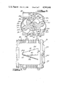
FIG. 1 is a side elevational view of the Roots-type blower;
FIG. 2 is a schematic sectional view of the blower looking along line 2--2 of FIG. 1;
FIG. 3 is a bottom view of a portion of the blower looking in the direction of arrow 3 in FIG. 1;
FIG. 4 is a top view of a portion of the blower looking along line 4--4 of FIG. 1;
FIG. 5 is a graph illustrating operational characteristics of the blower;
FIGS. 6-8 are reduced views of the blower section of FIG. 2 with the meshing relationships of the rotors therein varied;
FIGS. 9-14 are reduced schematic views of the left end of rotors shown in FIGS. 2 and 6-8 and looking along line 9--9 of FIG. 1; and
FIG. 15 is a somewhat schematic sectional view of the blower housing looking in the opposite direction of the arrows along line 9--9 of FIG. 1.
FIG. 16 is a reduced schematic view of the right end of the rotors looking along line 16--16 of FIG. 1.
DETAILED DESCRIPTION OF THE DRAWINGS
FIGS. 1-4 illustrate a rotary pump or blower 10 of the Roots-type. As previously mentioned, such blowers are used almost exclusively to pump or transfer volumes of compressible fluid, such as air, from an inlet port to an outlet port without compressing the transfer volumes prior to exposure to the outlet port. The rotors operate somewhat like gear-type pumps, i.e., as the rotor teeth or lobes move out of mesh, air flows into volumes or spaces defined by adjacent lobes on each rotor. The air in the volumes is then trapped therein at substantially inlet pressure when the top lands of the trailing lobe of each transfer volume moves into a sealing relation with the cylindrical wall surfaces of the associated chamber. The volumes of air are transferred or exposed to outlet air when the top land of the leading lobe of each volume moves out of sealing relation with the cylindrical wall surfaces by traversing the boundary of the outlet port. If the volume of the transfer volumes remains constant during the trip from inlet to outlet, the air therein remains at inlet pressure, i.e., transfer volume air pressure remains constant if the top lands of the leading lobes traverse the outlet port boundary before the volumes are squeezed by virtue of remeshing of the lobes. Hence, if air pressure at the discharge port is greater than inlet port pressure, outlet port air rushes or backflows into the transfer volumes as the top lands of the leading lobes traverse the outlet port boundary.
Blower 10 includes a housing assembly 12, a pair of lobed rotors 14, 16, and an input drive pulley 18. Housing assembly 12, as viewed in FIG. 1, includes a center section 20, left and right end sections 22, 24 secured to opposite ends of the center section by a plurality of bolts 26, and an outlet duct member 28 secured to the center section by a plurality of unshown bolts. The housing assembly and rotors are preferably formed from a lightweight material such as aluminum. The center section and end 24 define a pair of generally cylindrical working chambers 32, 34 circumferentially defined by cylindrical wall portions or surfaces 20a, 20b, an end wall surface indicated by phantom line 20c in FIG. 1, and an end wall surface 24a. Chambers 32, 34 traversely overlap or intersect at cusps 20d, 20e, as seen in FIG. 2. Openings 36, 38 in the bottom and top of center section 20 respectively define the transverse and longitudinal boundaries of inlet and outlet ports.
Rotors 14, 16 respectively include three circumferentially spaced apart helical teeth or lobes 14a, 14b, 14c and 16a, 16b, 16c of modified involute profile with an end-to-end twist of 60°. The lobes or teeth mesh and preferably do not touch. A sealing interface between meshing lobes 14c, 16c is represented by point M in FIG. 2. Interface or point M moves along the lobe profiles as the lobes progress through each mesh cycle and may be defined in several places as shown in FIG. 7. The lobes also include top lands 14d, 14e, 14f, and 16d, 16e, 16f. The lands move in close sealing noncontacting relation with cylindrical wall surfaces 20a, 20b and with the root portions of the lobes they are in mesh with. Rotors 14, 16 are respectively mounted for rotation in cylindrical chambers 32, 34 about axes coincident with the longitudinally extending, transversely spaced apart, parallel axes of the cylindrical chambers. Such mountings are well-known in the art. Hence, it should suffice to say that unshown shaft ends extending from and fixed to the rotors are supported by unshown bearings carried by end wall 20c and end section 24. Bearings for carrying the shaft ends extending rightwardly into end section 24 are carried by outwardly projecting bosses 24b, 24c. The rotors may be mounted and timed as shown in U.S. Pat. application Ser. No. 506,075, filed June 20, 1983 and incorporated herein by reference. Rotor 16 is directly driven by pulley 18 which is fixed to the left end of a shaft 40. Shaft 40 is either connected to or an extension of the shaft end extending from the left end of rotor 16. Rotor 14 is driven in a conventional manner by unshown timing gears fixed to the shaft ends extending from the left ends of the rotors. The timing gears are of the substantially no backlash type and are disposed in a chamber defined by a portion 22a of end section 22.
The rotors, as previously mentioned herein have three circumferentially spaced lobes of modified involute profile with an end-to-end helical twist of 60°. Rotors with other than three lobes, with different profiles and with different twist angles may be used to practice certain aspects or features of the inventions disclosed herein. However, to obtain uniform displacement based on meshing geometry and trapped volumes, the lobes are preferably provided with a helical twist from end-to-end which is substantially equal to the relation 360°/2n, where n equals the number of lobes per rotor. Further, involute profiles are also preferred since such profiles are more readily and accurately formed than most other profiles; this is particularly true for helically twisted lobes. Still further, involute profiles are preferred since they have been more readily and accurately timed during supercharger assembly.
As may be seen in FIG. 2, the rotor lobes and cylindrical wall surfaces sealingly cooperate to define an inlet receiver chamber 36a, an outlet receiver chamber 38a, and transfer volumes 32a, 34a. For the rotor positions of FIG. 2, inlet receiver chamber 36a is defined by portions of the cylindrical wall surfaces disposed between top lands 14e, 16e and the lobe surfaces extending from the top lands to the interface M of meshing lobes 14c, 16c. Interface M defines the point or points of closest contact between the meshing lobes. Likewise, outlet receiver chamber 38a is defined by portions of the cylindrical wall surfaces disposed between top lands 14d, 16d and the lobe surfaces extending from the top lands to the interface M of meshing lobes 14c, 16c. During each meshing cycle and as previously mentioned, meshing interface M moves along the lobe profile and is often defined at several places such as illustrated in FIGS. 6 and 7. The cylindrical wall surfaces defining both the inlet and outlet receiver chambers include those surface portions which were removed to define the inlet and outlet ports. Transfer volume 32a is defined by adjacent lobes 14a, 14b and the portion of cylindrical wall surfaces 20a disposed between top lands 14d, 14e. Likewise, transfer volume 34a is defined by adjacent lobes 16a, 16b and the portion of cylindrical wall surface 20b disposed between top lands 16d, 16e. As the rotors turn, transfer volumes 32a, 34a are reformed between subsequent pairs of adjacent lobes.
Inlet port 36 is provided with an opening shaped substantially like an isosceles trapezoid by wall surfaces 20f, 20g, 20h, 20i defined by housing section 20. Wall surfaces 20f, 20h define the longitudinal extent of the port and wall surfaces 20g, 20i define the transverse boundaries or extent of the port. The isosceles sides or wall surfaces 20g, 20i are matched or substantially parallel to the traversing top lands of the lobes. The top lands of the helically twisted lobes in both FIGS. 3 and 4 are schematically illustrated as being straight for simplicity herein. As viewed in FIGS. 3 and 4, such lands actually have a curvature. Wall surfaces 20g, 20i may be curved to more closely conform to the helical twist of the top lands.
Outlet port 38 is provided with a somewhat T-shaped opening by wall surfaces 20m, 20n, 20p, 20r, 20s, 20t defined by housing section 20. The top surface of housing 20 includes a recess 20w to provide an increased flow area for outlet duct 28. Wall surfaces 20m, 20r are parallel and define the longitudinal extent of the port. Wall surfaces 20p, 20s and their projections to surface 20m define the transverse boundaries or extent of the port for outflow of most air from the blower. Wall surfaces 20p, 20s are also parallel and may be spaced farther apart than shown herein if additional outlet port area is needed to prevent a pressure drop or back pressure across the outlet port. Diagonal wall surfaces 20n, 20t, which converge with transverse extensions of wall surface 20m at apexes 20x, 20z, define expanding orifices 42, 44 in combination with the traversing top lands of the lobes. The expanding orifices control the rate of back flow air into the transfer volumes. Orifices 42, 44 are designed to expand at a rate operative to maintain a substantially constant backflow rate of air into the transfer volumes when the blower operates at predetermined speed and differential pressure relationships. Apexes 20x, 20z are respectively spaced approximately 60 rotational degrees from surfaces 20p, 20s and are alternately traversed by the top lands of the associated lobes. The spacing between inlet port wall surfaces 20g, 20i and the apexes allows the top lands of the trailing lobes of each transfer volume to move into sealing relation with the cylindrical wall surfaces before backflow starts and allows a full 60° rotation of the lobes for backflow. Apexes 20x, 20z may be positioned to allow backflow slightly before the top lands of the trailing lobes of each transfer volume move into sealing relation with cylindrical wall surfaces 20a, 20b, thereby providing a slight overlap between the beginning and ending of backflow to ensure a smoother and continuous transition of backflow from one transfer volume to the the next.
Looking now for a moment at the graph of FIG. 5, therein curves S and H illustrate cyclic variations in volumetric displacement over 60° periods of rotor rotation. The variations are illustrated herein in terms of degrees of rotation but may be illustrated in terms of time. Such cyclic variations are due to the meshing geometry of the rotor lobes which effect the rate of change of volume of the outlet receiver chamber 38a. Since the inlet and outlet receiver chamber volumes vary at substantially the same rate and merely inverse to each other, the curves for outlet receiver chamber 38a should suffice to illustrate the rate of volume change for both chambers. Curve S illustrates the rate of change for a blower having three straight lobes of modified involute profile per rotor and curve H for a blower having three 60° helical twist lobes of modified involute profile per rotor. As may be seen, the absolute value of rate-of-change is approximately 7% of theoretical displacement for straight lobe rotors while there is no variation in the rate of displacement for 60° helical lobes.
The rate of volume change or uniform displacement for both straight and helical lobes, as previously mentioned, is due in part to the meshing geometry of the lobes. For straight lobes, the meshing relationship of the lobes is the same along the entire length of the lobes, i.e., the meshing relationship at any cross section or incremental volume along the meshing lobes is the same. For example, interface or point M of FIG. 2 is the same along the entire length of the meshing lobes, and a line through the points is straight and parallel to the rotor axis. Hence, a rate of volume change, due to meshing geometry, is the same and additive for all incremental volumes along the entire length of the meshing lobes. This is not the case for helical lobes formed according to the relation 360°/2n. For three lobe rotors having 60° helical lobes, the meshing relationship varies along the entire length of the meshing lobes over a 60° period. For example, if the meshing lobes were divided into 60 incremental volumes along their length, 60 different meshing relationships would exist at any given time, and a specific meshing relationship, such as illustrated in FIG. 2, would first occur at one end of the meshing lobes and then be sequentially repeated for each incremental volume as the rotors turn through 60 rotational degrees. If the meshing relationship of an incremental volume at one end of meshing lobes tends to increase the rate of volume change, the meshing relationship of the incremental volume at the other end of the meshing lobes tends to decrease the rate of volume change an equal amount. This additive-substractive or canceling relationship exists along the entire length of the meshing lobes and thereby cancels rates of volume change or provides uniform displacement with respect to meshing geometry.
Volumes of fluid trapped between meshing lobes are another cause or source affecting the rate of cyclic volume change of the receiver chambers. The trapped volumes are abruptly removed from the outlet receiver chamber and abruptly returned or carried back to the inlet receiver chamber. The trapped volumes also reduce blower displacement and pumping efficiency. Curves ST and HT in the graph of FIG. 5 respectively illustrate the rate of cyclic volume change of the outlet receiver chamber due to trapped volumes for straight and 60° helical twist lobes. As may be seen, the rate of volume change, as a percentage of theoretical displacement due to trapped volumes, is approximately 4.5 times greater for straight lobes. The total rate of volume change of the receiver chamber is obtained by adding the associated curves for meshing geometry and trapped volume together.
Looking briefly at the rightward sectioned end of the rotors, as illustrated in FIGS. 6 and 7, therein is shown areas trapped between adjacent lobes 14a, 14c and 16c. The areas may be thought of as incremental volumes when they have a small depth. The area for the meshing relationship of FIG. 6 represents a maximum incremental volume TV1. With reference to FIG. 7, as the rotors turn, incremental volume TV1, decreases in size while a second incremental volume TV2 is formed which increases in size.
For straight lobe rotors, each maximum incremental volume TV1, is formed along the entire length of the meshing lobes at substantially the same instant. Likewise, each incremental volume TV2 is formed along the entire length of the meshing lobes at substantially the same instant. Hence, the sums ΣTV1 and ΣTV2 of the incremental volumes define or form trapped volumes. ΣTV1 and ΣTV2 contribute to airborne noise and reduced blower efficiency. Both, particularly ΣTV1, cause substantial rates of volume change as illustrated in the graph of FIG. 5. The carryback of fluid in ΣTV1 and the respective decrease and increase in the size of ΣTV1 and ΣTV2 directly reduce blower efficiency.
Helical lobes greatly reduce the size of ΣTV1 and ΣTV2 ; this may be illustrated with reference to FIG. 6, which is a sectioned view of the rightward end of the rotors. With helical lobes, incremental volume TV1 at the rightward end of meshing lobes 14a, 14c and 16c is not trapped and subsequent incremental volumes TV1 from right-to-left are not trapped until the leftward end of lobes 14a, 14c and 16c move into the same meshing relationship. For 60° twist lobes this does not occur until the rotors turn an additional 60°. During this 60° period, each successive incremental volume TV1 from right-to-left decreases in size while still in communication with the outlet receiver chamber. Hence, the number of trapped incremental volumes TV1 is greatly reduced. Further, the total volume of this number of trapped incremental volumes is less than the total volume of a comparable number of straight lobe incremental volumes since trapped incremental volumes with helical lobes vary in cross-sectional area from a minimum to a maximum. The number of trapped incremental volumes TV2 and their total volume is the same as described for incremental volumes TV1. However, their formation sequence occurs in the reverse order, i.e., when incremental volume TV2 starts to form and expand at the right end of the lobes, it and subsequent incremental volumes TV2 are trapped until the right end of the lobes moves to the meshing relationship shown in FIG. 8; from thereon all incremental volumes TV2 are in constant communication with the inlet receiver chamber.
Referring now to the schematic illustrations of FIGS. 9-14, therein is shown a meshing cycle viewed from the left end of helical meshing lobes 14 and 16b, 16c with the projections of two passages or channels 46, 48 superimposed thereon. The channels, as shown in FIG. 15, are formed in the surface of left end wall 20c and provide communication between incremental volumes TV1 and TV2 as they respectively decrease and increase in size. Bearings which would normally be seen in bores 61, 63 in end wall 20c are omitted for simplicity. The channels may be straight, but are preferably formed with arcuate sides having their respective centers of radius located at the axes of rotation 50, 52 of the rotors. The side walls formed by the smaller radii are substantially the same as the root diameters or root radii 54, 56 of the lobes. Both channels are approximately 30° in arc length and are centered about an unshown line extended between the axes of rotation. Keeping in mind that the rotors are being viewed from the left end in FIGS. 9-14, when the left end of lobe 14c is in the position shown in FIG. 9, i.e., in sealing relation with lobe 16b and just prior to moving into a sealing relation with lobe 16c as shown in FIG. 10, the right end of lobe 14c has already moved out of sealing relation with the lobe 16b as shown in FIG. 2. As the lobes continue to rotate, incremental volume TV1 at the left end of the lobes becomes trapped as shown in FIG. 10, thereby completing the trapping of a series of incremental volumes of decreasing cross-sectional area to the right to define the sum of trapped incremental volumes ΣTV1 containing air at outlet pressure. The sequence of FIGS. 10-13 illustrate incremental volume TV1 and trapped incremental volume ΣTV1 decreasing in size from a maximum to a minimum while incremental volume TV2 forms and increases in size from a minimum to a maximum. During the sequence TV1 and TV2 are in communication with each other via arcuate channel 46 and TV2 is in continuous communication with inlet receiver chamber 36a. Hence, compression of the air in ΣTV1 is prevented by venting to the inlet receiver chamber.
FIG. 16 schematically illustrates a meshing relationship of lobes 14c and 16a, 16c viewed from the right end of the rotors with projections of two passages or channels 58, 60 superimposed thereon. In a manner analogous to channels 46, 48, channels 58, 60 are formed in the surface of right end wall 24a. Channels 58, 60 provide communication between incremental volumes TV1 and TV2 as they respectively decrease and increase in size. Channels 58, 60 are preferably positioned and sized the same as channels 46, 48. At this end of the lobes, i.e., the right end, TV1 is in continuous communication with outlet receiver chamber 38a, and TV2 and the expanding sum of incremental volumes ΣTV2 to its left are trapped until the lobes move to the position of FIG. 8. Hence, outlet receiver chamber air is vented to TV2 to prevent a vacuum tending as ΣTV2 expands.
The preferred embodiment of the invention has been disclosed in detail for illustrative purposes. Many variations of the disclosed embodiment are believed to be within the spirit of the invention.
The following claims are intended to cover inventive portions of the disclosed embodiment and modifications believed to be within the spirit of the invention.

Claims (12)

What is claimed is:
1. In a rotary blower of the backflow type including a housing defining first and second parallel, transversely overlapping cylindrical chambers having cylindrical and end wall surfaces; first and second meshed lobed rotors respectively disposed in the first and second chambers for transferring volumes of compressible low-pressure inlet port fluid via spaces between adjacent unmeshed lobes of each rotor to high-pressure outlet port fluid, the rotors and lobes sealingly cooperate with the wall surfaces, and the meshing lobes sealingly cooperate with each other; first and second volumes defined by spaces between the meshing lobes, the first volume isolated from the second volume and the ports by the sealing cooperation during at least a portion of each mesh of the lobes, and the first volume containing outlet port fluid and decreasing in size from a maximum to a minimum while the second volume increases in size from a minimum to a maximum; the improvement comprising:
first and second passages formed in at least one end wall of said chambers for alternately communicating alternately formed first volumes with the associated second volumes during alternate meshes of the lobes.
2. The blower of claim 1, wherein the rotor lobes are straight and the second volume is also isolated from the ports.
3. The blower of claim 1, wherein the rotor lobes are helical and each second volume is in communication with each first volume via said passages.
4. The blower of claim 1, wherein said first and second passages are respectively associated with the root diameter of the first and second rotors.
5. The blower of claim 4, wherein said passages are channels formed in said one end wall surface.
6. The blower of claim 4, wherein said passages are arcuate channels formed in said one end wall surface with the radius of each centered substantially at the rotational axis of the associated rotor.
7. The blower of claim 6, wherein each arcuate channel has an arc length of substantially 30° centered about a line extending between the axes rotor rotation.
8. The blower of claim 1, wherein the rotor lobes are formed with a helical twist, whereby one end of the lobes moves into a meshing relationship forming the first and second volumes prior to the other end of the lobes moving into such a meshing relationship; the first volume formed at the one end of the lobes being in communication with the outlet port until the other end of the lobes moves into said such a meshing relationship; the second volume formed at the one end of the lobes initially isolated from the ports and subsequentially communicated with the inlet port prior to said such a meshing relationship at the other end of the lobes; said first and second passages disposed adjacent the other end of the lobes in said one end wall for alternately communicating alternately formed first volumes with the associated second volumes while the second volumes communicate with the inlet port; and third and fourth passages formed in the other end wall for alternately communicating alternately formed second volumes with the associated first volumes while the first volumes communicate with the outlet port.
9. The blower of claim 8, wherein said first and second passages are respectively associated with the root diameter of the first and second rotors.
10. The blower of claim 9, wherein said passages are channels formed in said one end wall surface.
11. The blower of claim 9, wherein said passages are arcuate channels formed in said one end wall surface with the radius of each centered substantially at the rotational axis of the associated rotor.
12. The blower of claim 11, wherein each arcuate channel has an arc length of substantially 30° centered about a line extending between the axes rotor rotation.
US06/647,074 1984-09-04 1984-09-04 Supercharger carry-over venting means Expired - Lifetime US4569646A (en)

Priority Applications (4)

Application Number Priority Date Filing Date Title
US06/647,074 US4569646A (en) 1984-09-04 1984-09-04 Supercharger carry-over venting means
DE8585306199T DE3576388D1 (en) 1984-09-04 1985-09-02 FLUID PRESSURE TRANSFER FOR CHARGER.
EP85306199A EP0176268B1 (en) 1984-09-04 1985-09-02 Supercharger carry-over venting means
JP60195702A JPS6181593A (en) 1984-09-04 1985-09-04 Blower for supercharger

Applications Claiming Priority (1)

Application Number Priority Date Filing Date Title
US06/647,074 US4569646A (en) 1984-09-04 1984-09-04 Supercharger carry-over venting means

Publications (1)

Publication Number Publication Date
US4569646A true US4569646A (en) 1986-02-11

Family

ID=24595582

Family Applications (1)

Application Number Title Priority Date Filing Date
US06/647,074 Expired - Lifetime US4569646A (en) 1984-09-04 1984-09-04 Supercharger carry-over venting means

Country Status (4)

Country Link
US (1) US4569646A (en)
EP (1) EP0176268B1 (en)
JP (1) JPS6181593A (en)
DE (1) DE3576388D1 (en)

Cited By (10)

* Cited by examiner, † Cited by third party
Publication number Priority date Publication date Assignee Title
US5118268A (en) * 1991-06-19 1992-06-02 Eaton Corporation Trapped volume vent means with restricted flow passages for meshing lobes of roots-type supercharger
US5131829A (en) * 1991-06-19 1992-07-21 Eaton Corporation Trapped volume vent means for meshing lobes of roots-type supercharger
EP0519276A1 (en) * 1991-06-19 1992-12-23 Eaton Corporation Supercharger carry-over venting means
US20070280846A1 (en) * 2006-06-05 2007-12-06 Denso Corporation Screw compressor
US20080166254A1 (en) * 2006-09-28 2008-07-10 Martin Jordan Hydraulic device
US20080193301A1 (en) * 2007-02-13 2008-08-14 Kabushiki Kaisha Toyota Jidoshokki Composite fluid machine
CN104047864A (en) * 2013-03-15 2014-09-17 伊顿公司 Bearing plate bleed port for roots-type superchargers
US20150118086A1 (en) * 2005-05-23 2015-04-30 Eaton Corporation Optimized helix angle rotors for roots-style supercharger
US9683521B2 (en) 2013-10-31 2017-06-20 Eaton Corporation Thermal abatement systems
USD816717S1 (en) 2014-08-18 2018-05-01 Eaton Corporation Supercharger housing

Citations (14)

* Cited by examiner, † Cited by third party
Publication number Priority date Publication date Assignee Title
US859762A (en) * 1907-01-23 1907-07-09 Wilbraham Green Blower Company Rotary blower or exhauster.
US1719025A (en) * 1924-04-17 1929-07-02 Petroleum Heat & Power Co Rotary-gear pump
US2014932A (en) * 1933-03-17 1935-09-17 Gen Motors Corp Roots blower
US2078334A (en) * 1935-03-28 1937-04-27 Joseph A Martocello Blower
US2463080A (en) * 1945-02-17 1949-03-01 Schwitzer Cummins Company Interengaging impeller fluid pump
US2480818A (en) * 1943-05-11 1949-08-30 Joseph E Whitfield Helical rotary fluid handling device
US2578196A (en) * 1946-11-30 1951-12-11 Imo Industri Ab Screw compressor
US3121529A (en) * 1962-05-02 1964-02-18 Polysius Gmbh Blower
US3275226A (en) * 1965-02-23 1966-09-27 Joseph E Whitfield Thrust balancing and entrapment control means for screw type compressors and similardevices
US3531227A (en) * 1968-07-05 1970-09-29 Cornell Aeronautical Labor Inc Gear compressors and expanders
US3667874A (en) * 1970-07-24 1972-06-06 Cornell Aeronautical Labor Inc Two-stage compressor having interengaging rotary members
US3844695A (en) * 1972-10-13 1974-10-29 Calspan Corp Rotary compressor
US4097206A (en) * 1975-12-02 1978-06-27 Robert Bosch Gmbh Gear pump or motor with bypass throttle passage to prevent cavitation
US4215977A (en) * 1977-11-14 1980-08-05 Calspan Corporation Pulse-free blower

Family Cites Families (5)

* Cited by examiner, † Cited by third party
Publication number Priority date Publication date Assignee Title
NL293617A (en) * 1900-01-01
FR627749A (en) * 1927-01-12 1927-10-11 Gear wheel rotary compressor, pump and equivalent devices
US3303792A (en) * 1964-04-20 1967-02-14 Roper Ind Inc Gear pump with trapping reliefs
DE1553090A1 (en) * 1965-12-10 1970-01-08 Kracht Pumpen Motoren Gear pump or motor for high pressures
FR1594801A (en) * 1968-11-20 1970-06-08

Patent Citations (14)

* Cited by examiner, † Cited by third party
Publication number Priority date Publication date Assignee Title
US859762A (en) * 1907-01-23 1907-07-09 Wilbraham Green Blower Company Rotary blower or exhauster.
US1719025A (en) * 1924-04-17 1929-07-02 Petroleum Heat & Power Co Rotary-gear pump
US2014932A (en) * 1933-03-17 1935-09-17 Gen Motors Corp Roots blower
US2078334A (en) * 1935-03-28 1937-04-27 Joseph A Martocello Blower
US2480818A (en) * 1943-05-11 1949-08-30 Joseph E Whitfield Helical rotary fluid handling device
US2463080A (en) * 1945-02-17 1949-03-01 Schwitzer Cummins Company Interengaging impeller fluid pump
US2578196A (en) * 1946-11-30 1951-12-11 Imo Industri Ab Screw compressor
US3121529A (en) * 1962-05-02 1964-02-18 Polysius Gmbh Blower
US3275226A (en) * 1965-02-23 1966-09-27 Joseph E Whitfield Thrust balancing and entrapment control means for screw type compressors and similardevices
US3531227A (en) * 1968-07-05 1970-09-29 Cornell Aeronautical Labor Inc Gear compressors and expanders
US3667874A (en) * 1970-07-24 1972-06-06 Cornell Aeronautical Labor Inc Two-stage compressor having interengaging rotary members
US3844695A (en) * 1972-10-13 1974-10-29 Calspan Corp Rotary compressor
US4097206A (en) * 1975-12-02 1978-06-27 Robert Bosch Gmbh Gear pump or motor with bypass throttle passage to prevent cavitation
US4215977A (en) * 1977-11-14 1980-08-05 Calspan Corporation Pulse-free blower

Cited By (14)

* Cited by examiner, † Cited by third party
Publication number Priority date Publication date Assignee Title
US5131829A (en) * 1991-06-19 1992-07-21 Eaton Corporation Trapped volume vent means for meshing lobes of roots-type supercharger
EP0519276A1 (en) * 1991-06-19 1992-12-23 Eaton Corporation Supercharger carry-over venting means
US5118268A (en) * 1991-06-19 1992-06-02 Eaton Corporation Trapped volume vent means with restricted flow passages for meshing lobes of roots-type supercharger
US20150118086A1 (en) * 2005-05-23 2015-04-30 Eaton Corporation Optimized helix angle rotors for roots-style supercharger
US9822781B2 (en) * 2005-05-23 2017-11-21 Eaton Corporation Optimized helix angle rotors for roots-style supercharger
US20070280846A1 (en) * 2006-06-05 2007-12-06 Denso Corporation Screw compressor
US7722345B2 (en) * 2006-06-05 2010-05-25 Denso Corporation Screw compressor
US8512018B2 (en) * 2006-09-28 2013-08-20 Trw Automotive Gmbh Gear pump with pressure relief groove
US20080166254A1 (en) * 2006-09-28 2008-07-10 Martin Jordan Hydraulic device
US20080193301A1 (en) * 2007-02-13 2008-08-14 Kabushiki Kaisha Toyota Jidoshokki Composite fluid machine
CN104047864A (en) * 2013-03-15 2014-09-17 伊顿公司 Bearing plate bleed port for roots-type superchargers
US9683521B2 (en) 2013-10-31 2017-06-20 Eaton Corporation Thermal abatement systems
US11085403B2 (en) 2013-10-31 2021-08-10 Eaton Intelligent Power Limited Thermal abatement systems
USD816717S1 (en) 2014-08-18 2018-05-01 Eaton Corporation Supercharger housing

Also Published As

Publication number Publication date
EP0176268B1 (en) 1990-03-07
JPS6181593A (en) 1986-04-25
EP0176268A1 (en) 1986-04-02
DE3576388D1 (en) 1990-04-12

Similar Documents

Publication Publication Date Title
US4609335A (en) Supercharger with reduced noise and improved efficiency
US4768934A (en) Port arrangement for rotary positive displacement blower
US4564345A (en) Supercharger with reduced noise
US4556373A (en) Supercharger carryback pulsation damping means
AU2006202131B2 (en) Optimized helix angle rotors for roots-style supercharger
US9822781B2 (en) Optimized helix angle rotors for roots-style supercharger
US3844695A (en) Rotary compressor
US4569646A (en) Supercharger carry-over venting means
US10436197B2 (en) Optimized helix angle rotors for roots-style supercharger
US5118268A (en) Trapped volume vent means with restricted flow passages for meshing lobes of roots-type supercharger
EP0246382B1 (en) Backflow passage for rotary blower of the roots-type
KR100606613B1 (en) A gear and fluid machine with a pair of gears
US4564346A (en) Supercharger with hourglass outlet port
CA2029609C (en) Pulse tuned optimized positive displacement porting
EP0174171B1 (en) Supercharger with reduced noise
JP3189069B2 (en) Rotary pump for roots type supercharger
USRE29627E (en) Rotary compressor
US4437818A (en) Oil-free rotary compressor
US20190383287A1 (en) Optimized helix angle rotors for roots-style supercharger
EP2213906B1 (en) A gear and a fluid machine with a pair of gears

Legal Events

Date Code Title Description
AS Assignment

Owner name: EATON CORPORATION 1111 SUPERIOR AVE. CLEVELAND, OH

Free format text: ASSIGNMENT OF ASSIGNORS INTEREST.;ASSIGNOR:SOETERS, RAYMOND A. JR;REEL/FRAME:004306/0433

Effective date: 19840810

FEPP Fee payment procedure

Free format text: PAYOR NUMBER ASSIGNED (ORIGINAL EVENT CODE: ASPN); ENTITY STATUS OF PATENT OWNER: LARGE ENTITY

STCF Information on status: patent grant

Free format text: PATENTED CASE

FPAY Fee payment

Year of fee payment: 4

FPAY Fee payment

Year of fee payment: 8

FEPP Fee payment procedure

Free format text: PAYER NUMBER DE-ASSIGNED (ORIGINAL EVENT CODE: RMPN); ENTITY STATUS OF PATENT OWNER: LARGE ENTITY

Free format text: PAYOR NUMBER ASSIGNED (ORIGINAL EVENT CODE: ASPN); ENTITY STATUS OF PATENT OWNER: LARGE ENTITY

FPAY Fee payment

Year of fee payment: 12