US4552060A - Apparatus for the continuous boiling of wort - Google Patents
Apparatus for the continuous boiling of wort Download PDFInfo
- Publication number
- US4552060A US4552060A US06/650,514 US65051484A US4552060A US 4552060 A US4552060 A US 4552060A US 65051484 A US65051484 A US 65051484A US 4552060 A US4552060 A US 4552060A
- Authority
- US
- United States
- Prior art keywords
- heat exchanger
- wort
- separator
- temperature
- housing
- Prior art date
- Legal status (The legal status is an assumption and is not a legal conclusion. Google has not performed a legal analysis and makes no representation as to the accuracy of the status listed.)
- Expired - Fee Related
Links
Images


Classifications
-
- C—CHEMISTRY; METALLURGY
- C12—BIOCHEMISTRY; BEER; SPIRITS; WINE; VINEGAR; MICROBIOLOGY; ENZYMOLOGY; MUTATION OR GENETIC ENGINEERING
- C12C—BEER; PREPARATION OF BEER BY FERMENTATION; PREPARATION OF MALT FOR MAKING BEER; PREPARATION OF HOPS FOR MAKING BEER
- C12C7/00—Preparation of wort
- C12C7/20—Boiling the beerwort
- C12C7/205—Boiling with hops
- C12C7/22—Processes or apparatus specially adapted to save or recover energy
-
- C—CHEMISTRY; METALLURGY
- C12—BIOCHEMISTRY; BEER; SPIRITS; WINE; VINEGAR; MICROBIOLOGY; ENZYMOLOGY; MUTATION OR GENETIC ENGINEERING
- C12C—BEER; PREPARATION OF BEER BY FERMENTATION; PREPARATION OF MALT FOR MAKING BEER; PREPARATION OF HOPS FOR MAKING BEER
- C12C13/00—Brewing devices, not covered by a single group of C12C1/00 - C12C12/04
- C12C13/02—Brew kettles
- C12C13/025—Brew kettles heated with steam
Definitions
- the invention relates to apparatus for the continuous boiling of wort according to the preamble to claim 1
- the object of the invention is to develop this known apparatus for continuous boiling, of wort so that the expenditure on plant and the space required are considerably reduced and an even better degree of efficiency is achieved from the point of view of heat engineering.
- recuperative heat exchangers connected in series for gradual raising of the temperature of the wort and two separators connected in series for gradual depressurisation and lowering of the temperature of the wort are provided in the usual way, then according to the invention the first separator is combined with the second recuperative heat exchanger into one structural unit and the second separator is combined with the first recuperative heat exchanger into one structural unit.
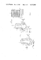
- FIG. 1 shows a general layout of apparatus according to the invention for continuous boiling of wort
- FIGS. 2 and 3 each show the layout of an embodiment of a combined separator and heat exchanger.
- the apparatus shown in FIG. 1 for continuous boiling of wort contains two recuperative heat exchangers 1 and 2 for raising the temperature of the wort and a further heat exchanger 3 which is supplied for example with live steam for raising the temperature of the wort to the boiling temperature.
- the apparatus also contains a heat maintaining section 4 as well as two separators 5 and 6 for depressurisation and lowering of the temperature of the wort as well as for separating off the vapour.
- recuperative heat exchanger 1 and the separator 6 are combined into one structural unit (housing 7). In the same way the heat exchanger 2 and the separator 5 are accommodated in one common housing 8.
- the hopped wort is delivered to the recuperative heat exchanger by a pressure increasing pump 9 and a pipe 10 at a temperature of approximately 72° C.
- the wort is heated in this heat exchanger to a temperature of approximately 90° to 92° C. and then passes via a pipe 11 to the recuperative heat exchanger 2 which raises the temperature of the wort to approximately 110° to 112° C.
- the wort is delivered via a pipe 12 to a heat exchanger 3 which raises the temperature of the wort to the boiling temperature, for example approximately 140° C.
- the wort is under a pressure of approximately 3.5 bars.
- the wort passes via a pipe 13 into the heat maintaining zone 4 in which the pressure and the temperature are maintained by means of a pressure maintaining valve 15.
- the isomerisation and coagulation of the albumin take place in this heat maintaining zone.
- the wort then passes through the pressure release loop 16 in which the kinetic energy is somewhat reduced before it enters the separator 5 through a tangential inlet 17.
- the wort is depressurised to some extent, so that the temperature is lowered to approximately 120° C. With this depressurisation the vapours are separated off and--as will be explained in greater detail in connection with FIGS. 2 and 3--rise into the upper space in the housing 8 and there form the heating medium for the recuperative heat exchanger 2.
- the wort collects in the lower region of the separating chamber 18 and is extracted via a filling level regulating valve 19 and a pipe 20.
- the filling level regulating valve 19 is controlled by two pressure gauges 21, 22 which measure according to the difference principle.
- the condensate obtained in the heat exchanger is drawn off via a control valve 23 which is controlled by a temperature gauge 24 which measures the temperature of the wort in the pipe 20.
- the wort then passes via the pipe 20 and a tangential inlet 25 into the separator 6 in which it is depressurised to atmospheric pressure, during which its temperature is lowered to approximately 100° C.
- the vapour produced during this depressurisation rises into the upper part of the housing 7 and there forms the heating medium for the recuperative heat exchanger 1.
- the wort is extracted from the separator 6 via a pipe 26 and a pump 27, the filling level being maintained in the lower region of the separator 6 by a filling level regulating valve 28 which receives its signals from two pressure gauges 29, 30.
- the condensate is extracted from the heat exchanger 1 via a pipe 31 with a siphon 32 and a shut-off valve 33.
- FIG. 2 A first embodiment of a combined heat exchanger and separator is shown in FIG. 2.
- the recuperative heat exchanger 1 and the separator 6 are accommodated in a common housing 7 (the same applies to the heat exchanger 2 and the separator 5, so a separate description thereof is superfluous).
- the housing 7 is divided by a partition 34 into two chambers 35, 36 lying one above the other, of which the lower chamber 35 forms the separating chamber and the upper chamber 36 contains the heat exchanger 1.
- the partition is provided with a central opening 37 and a plurality of peripheral openings 38 for the vapour to pass through (arrows 39).
- the heat exchanger 1 is formed by two helical pipes 40, 41 which are arranged coaxially one inside the other and are advantageously joined in parallel.
- the inlet connection 42 and the outlet connection 43 for the wort are provided in the cover 7a of the housing so that the heat exchanger 1 can be removed from the rest of the housing body with the housing cover 7a.
- the wort inlet connection 42 is connected to the lower end of the heat exchanger 1 and the outlet connection 43 is connected to the upper end thereof.
- the reverse connection is also possible within the scope of the invention.
- the partition 34 has a channel below the pipes 40, 41 and the base of the channel is provided with a connection 44 for extraction of the collected condensate.
- Cleaning sprays 45 are provided in the lower and upper chambers 35 and 36 respectively of the housing 7. Finally, a vacuum valve 46 and a safety valve 47 are arranged in the housing cover.
- the tangential inlet for the wort is designated by 25 and the connection for the extraction of the wort is designated by 48.
- a manhole 49 facilitates inspection of the interior of the housing.
- the housing 7' is also divided by a partition 34' into a lower chamber 35' forming the separating chamber and an upper chamber 36' containing the heat exchanger 1'.
- the partition 34' falls off conically outwards and is provided with a tubular extension 50 which forms a central opening 51 for the vapour. Leaving an annular clearance 52, this tubular extension 50 engages in a conduit 53 which projects into the upper region of the chamber 36' and is surrounded by the heat exchanger 1'. The diameter of the conduit 53 is somewhat greater than that of the opening 51 thus forming the said annular clearance 52 which is open towards the lower region of the chamber 36'.
- the inlet connection for the heat exchanger 1' is designated by 43'.
- the condensate produced in the chamber 36' is led off via the connection 44'.
- the inlet to the separating chamber 35' (is designated by 25', and the connection for extraction of the depressurised wort is designated by 48'.
- cleaning sprays 45' are provided for the two chambers 35', 36' of the housing.
- vapour formed in the separating chamber 35' when the wort is depressurised rises upwards through the tubular extension 50 and the conduit 53 (arrow 54) and a certain gas circulation can occur in the chamber 36' above the annular clearance 52.
Landscapes
- Chemical & Material Sciences (AREA)
- Organic Chemistry (AREA)
- Engineering & Computer Science (AREA)
- Bioinformatics & Cheminformatics (AREA)
- Life Sciences & Earth Sciences (AREA)
- Biochemistry (AREA)
- Health & Medical Sciences (AREA)
- General Engineering & Computer Science (AREA)
- General Health & Medical Sciences (AREA)
- Genetics & Genomics (AREA)
- Food Science & Technology (AREA)
- Wood Science & Technology (AREA)
- Zoology (AREA)
- Distillation Of Fermentation Liquor, Processing Of Alcohols, Vinegar And Beer (AREA)
Applications Claiming Priority (2)
| Application Number | Priority Date | Filing Date | Title |
|---|---|---|---|
| DE3303671 | 1983-02-03 | ||
| DE19833303671 DE3303671A1 (de) | 1983-02-03 | 1983-02-03 | Anlage zur kontinuierlichen wuerzekochung |
Publications (1)
| Publication Number | Publication Date |
|---|---|
| US4552060A true US4552060A (en) | 1985-11-12 |
Family
ID=6189966
Family Applications (1)
| Application Number | Title | Priority Date | Filing Date |
|---|---|---|---|
| US06/650,514 Expired - Fee Related US4552060A (en) | 1983-02-03 | 1984-02-01 | Apparatus for the continuous boiling of wort |
Country Status (5)
| Country | Link |
|---|---|
| US (1) | US4552060A (de) |
| JP (1) | JPS60500399A (de) |
| DE (1) | DE3303671A1 (de) |
| GB (1) | GB2142932B (de) |
| WO (1) | WO1984003101A1 (de) |
Cited By (21)
| Publication number | Priority date | Publication date | Assignee | Title |
|---|---|---|---|---|
| US4814189A (en) * | 1986-06-19 | 1989-03-21 | Societe Thermique Generale Vinicole | Process and apparatus for thermal control of winemaking |
| US4836097A (en) * | 1986-11-20 | 1989-06-06 | Anton Steinecker Maschinenfabrik Gmbh | Whirlpool for coarse sludge separation in brewing of beer |
| US5168920A (en) * | 1990-06-19 | 1992-12-08 | Anton Steinecker Entwicklungs Gmbh & Co. | Wort boiler apparatus with external boiler |
| US5522305A (en) * | 1994-02-16 | 1996-06-04 | Anton Steinecker Maschinenfabrik Gmbh | Wort kettle for boiling wort for brewing |
| US5762991A (en) * | 1992-12-31 | 1998-06-09 | Metalgesellschaft Aktiengesellschaft | Continous process of producing beer |
| US6017568A (en) * | 1994-03-25 | 2000-01-25 | Heineken Technical Services B.V. | Process for the continuous boiling of wort |
| US20120000367A1 (en) * | 2009-03-19 | 2012-01-05 | Rudolf Michel | Brewery Facility for Producing and Bottling Beer |
| US20150000532A1 (en) * | 2011-03-03 | 2015-01-01 | PicoBrew, LLC | Cascading Hops Reservoirs for Recirculating Brewing System |
| CN108048268A (zh) * | 2017-11-29 | 2018-05-18 | 浦江县泰如食品科技有限公司 | 低能耗的麦汁煮沸装置 |
| US10161533B2 (en) | 2016-05-09 | 2018-12-25 | Picobrew, Inc. | Bi-stable electrically actuated valve |
| US10176340B2 (en) | 2016-03-13 | 2019-01-08 | DataSpark, PTE. LTD. | Abstracted graphs from social relationship graph |
| US10308903B2 (en) | 2014-09-17 | 2019-06-04 | Picobrew, Inc. | Foam reducing device |
| US10377981B2 (en) | 2015-03-17 | 2019-08-13 | Picobrew, Inc. | Software tuning of recipes for beer brewing system |
| US10463983B2 (en) | 2017-03-31 | 2019-11-05 | Picobrew, Inc. | Distillation and essence extractor insert for beer brewing machine |
| US10479966B2 (en) | 2015-07-31 | 2019-11-19 | Picobrew, Inc. | Fermentation monitoring and management |
| US10762538B2 (en) | 2014-04-24 | 2020-09-01 | DataSpark, PTE. LTD. | Knowledge model for personalization and location services |
| US10841852B2 (en) | 2015-12-09 | 2020-11-17 | DataSpark, PTE. LTD. | Transportation network monitoring using cellular radio metadata |
| US11157520B2 (en) | 2016-03-28 | 2021-10-26 | DataSpark, Pte Ltd. | Uniqueness level for anonymized datasets |
| US11299695B2 (en) | 2015-07-23 | 2022-04-12 | PB Funding Group, LLC | Beer making machine with direct steam injection |
| US11678760B2 (en) | 2011-03-03 | 2023-06-20 | PB Funding Group, LLC | Multifunctional brewing system for coffee, beer, and other beverages |
| US11753610B2 (en) | 2011-03-03 | 2023-09-12 | PB Funding Group, LLC | Self healing controller for beer brewing system |
Families Citing this family (4)
| Publication number | Priority date | Publication date | Assignee | Title |
|---|---|---|---|---|
| DE3501805A1 (de) * | 1985-01-21 | 1986-07-24 | Anton Steinecker Maschinenfabrik Gmbh, 8050 Freising | Behaelter fuer die kochung von maische oder wuerze |
| GB2175006B (en) * | 1985-05-06 | 1989-08-02 | Stroh Brewery Corp | Method and apparatus of brewing |
| HU195243B (en) * | 1985-06-03 | 1988-04-28 | Koebanyai Soergyar | Process and apparatus for energy economical continuous hop-brewing |
| DE102007052471A1 (de) * | 2007-11-02 | 2009-05-07 | Krones Ag | Kontinuierliches Brauen |
Citations (5)
| Publication number | Priority date | Publication date | Assignee | Title |
|---|---|---|---|---|
| US3102813A (en) * | 1959-11-20 | 1963-09-03 | Apv Co Ltd | Processing of brewers' wort |
| US3535116A (en) * | 1965-12-24 | 1970-10-20 | Eugen Harsanyi | Process for the continuous production of wort |
| FR2442886A1 (fr) * | 1978-05-09 | 1980-06-27 | Tepral Grpt Interet Economique | Installation et procede de cuisson en continu pour mout de brasserie |
| US4388857A (en) * | 1980-04-01 | 1983-06-21 | Kraftanlagen A.G. | Apparatus for the continuous cooking of wort |
| US4483881A (en) * | 1981-12-02 | 1984-11-20 | Bernhard Lenz | Process for discontinuous wort boiling during beer manufacture |
Family Cites Families (1)
| Publication number | Priority date | Publication date | Assignee | Title |
|---|---|---|---|---|
| DE3029531A1 (de) * | 1980-08-04 | 1982-03-04 | Georg 6200 Wiesbaden Kraus | Kontinuierliches verfahren zur herstellung von bierwuerze |
-
1983
- 1983-02-03 DE DE19833303671 patent/DE3303671A1/de not_active Withdrawn
-
1984
- 1984-02-01 WO PCT/DE1984/000026 patent/WO1984003101A1/de unknown
- 1984-02-01 US US06/650,514 patent/US4552060A/en not_active Expired - Fee Related
- 1984-02-01 GB GB08423257A patent/GB2142932B/en not_active Expired
- 1984-02-01 JP JP59500730A patent/JPS60500399A/ja active Granted
Patent Citations (5)
| Publication number | Priority date | Publication date | Assignee | Title |
|---|---|---|---|---|
| US3102813A (en) * | 1959-11-20 | 1963-09-03 | Apv Co Ltd | Processing of brewers' wort |
| US3535116A (en) * | 1965-12-24 | 1970-10-20 | Eugen Harsanyi | Process for the continuous production of wort |
| FR2442886A1 (fr) * | 1978-05-09 | 1980-06-27 | Tepral Grpt Interet Economique | Installation et procede de cuisson en continu pour mout de brasserie |
| US4388857A (en) * | 1980-04-01 | 1983-06-21 | Kraftanlagen A.G. | Apparatus for the continuous cooking of wort |
| US4483881A (en) * | 1981-12-02 | 1984-11-20 | Bernhard Lenz | Process for discontinuous wort boiling during beer manufacture |
Cited By (22)
| Publication number | Priority date | Publication date | Assignee | Title |
|---|---|---|---|---|
| US4814189A (en) * | 1986-06-19 | 1989-03-21 | Societe Thermique Generale Vinicole | Process and apparatus for thermal control of winemaking |
| US4836097A (en) * | 1986-11-20 | 1989-06-06 | Anton Steinecker Maschinenfabrik Gmbh | Whirlpool for coarse sludge separation in brewing of beer |
| US5168920A (en) * | 1990-06-19 | 1992-12-08 | Anton Steinecker Entwicklungs Gmbh & Co. | Wort boiler apparatus with external boiler |
| US5762991A (en) * | 1992-12-31 | 1998-06-09 | Metalgesellschaft Aktiengesellschaft | Continous process of producing beer |
| US5522305A (en) * | 1994-02-16 | 1996-06-04 | Anton Steinecker Maschinenfabrik Gmbh | Wort kettle for boiling wort for brewing |
| US6017568A (en) * | 1994-03-25 | 2000-01-25 | Heineken Technical Services B.V. | Process for the continuous boiling of wort |
| US20120000367A1 (en) * | 2009-03-19 | 2012-01-05 | Rudolf Michel | Brewery Facility for Producing and Bottling Beer |
| US20150000532A1 (en) * | 2011-03-03 | 2015-01-01 | PicoBrew, LLC | Cascading Hops Reservoirs for Recirculating Brewing System |
| US11753610B2 (en) | 2011-03-03 | 2023-09-12 | PB Funding Group, LLC | Self healing controller for beer brewing system |
| US11678760B2 (en) | 2011-03-03 | 2023-06-20 | PB Funding Group, LLC | Multifunctional brewing system for coffee, beer, and other beverages |
| US10762538B2 (en) | 2014-04-24 | 2020-09-01 | DataSpark, PTE. LTD. | Knowledge model for personalization and location services |
| US10308903B2 (en) | 2014-09-17 | 2019-06-04 | Picobrew, Inc. | Foam reducing device |
| US10377981B2 (en) | 2015-03-17 | 2019-08-13 | Picobrew, Inc. | Software tuning of recipes for beer brewing system |
| US11299695B2 (en) | 2015-07-23 | 2022-04-12 | PB Funding Group, LLC | Beer making machine with direct steam injection |
| US10479966B2 (en) | 2015-07-31 | 2019-11-19 | Picobrew, Inc. | Fermentation monitoring and management |
| US10841852B2 (en) | 2015-12-09 | 2020-11-17 | DataSpark, PTE. LTD. | Transportation network monitoring using cellular radio metadata |
| US10176340B2 (en) | 2016-03-13 | 2019-01-08 | DataSpark, PTE. LTD. | Abstracted graphs from social relationship graph |
| US11157520B2 (en) | 2016-03-28 | 2021-10-26 | DataSpark, Pte Ltd. | Uniqueness level for anonymized datasets |
| US11170027B2 (en) | 2016-03-28 | 2021-11-09 | DataSpark, Pte Ltd | Error factor and uniqueness level for anonymized datasets |
| US10161533B2 (en) | 2016-05-09 | 2018-12-25 | Picobrew, Inc. | Bi-stable electrically actuated valve |
| US10463983B2 (en) | 2017-03-31 | 2019-11-05 | Picobrew, Inc. | Distillation and essence extractor insert for beer brewing machine |
| CN108048268A (zh) * | 2017-11-29 | 2018-05-18 | 浦江县泰如食品科技有限公司 | 低能耗的麦汁煮沸装置 |
Also Published As
| Publication number | Publication date |
|---|---|
| JPS60500399A (ja) | 1985-03-28 |
| JPS6114792B2 (de) | 1986-04-21 |
| GB8423257D0 (en) | 1984-10-17 |
| WO1984003101A1 (en) | 1984-08-16 |
| GB2142932A (en) | 1985-01-30 |
| DE3303671A1 (de) | 1984-08-09 |
| GB2142932B (en) | 1986-06-11 |
Similar Documents
| Publication | Publication Date | Title |
|---|---|---|
| US4552060A (en) | Apparatus for the continuous boiling of wort | |
| EP0251667B1 (de) | Röhrenverdampfer | |
| US2078288A (en) | Method and apparatus for heating and deaerating boiler feed water | |
| AU719080B2 (en) | Deodorisation plant for fatty oils | |
| US2558222A (en) | Deaerating hot well | |
| US4353217A (en) | Direct contact type multi-stage steam condenser system | |
| GB2197660A (en) | Ship board system for dewatering of bottoms material discharged from heavy oil purifiers | |
| US4796570A (en) | Apparatus for heating steam formed from cooling water | |
| US3094165A (en) | Deaerating system for condensers | |
| US4813346A (en) | Wort cooking arrangement | |
| US1986165A (en) | Distillation apparatus | |
| SU1768864A1 (ru) | Ceпapatop-пapoпepeгpebateль | |
| US4681066A (en) | Boiler for boiling mash or wort | |
| US3279438A (en) | Waste heat recovery system for heat engines | |
| US799002A (en) | Water-still. | |
| US1804616A (en) | Multistage feed water heating | |
| US3068629A (en) | Cyclone separators in tiers | |
| US1321999A (en) | Treatment of liquids | |
| US1546641A (en) | Ejecting apparatus | |
| SU724449A1 (ru) | Способ вакуумной деаэрации воды | |
| SU1511525A1 (ru) | Деаэрационна установка | |
| SU958482A1 (ru) | Способ предварительной дистилл ции мисцеллы и установка дл его осуществлени | |
| SU660939A1 (ru) | Пр моточный деаэратор | |
| JPH0979513A (ja) | 熱媒体による低圧蒸気加熱装置 | |
| SU956911A1 (ru) | Продувочное устройство котла |
Legal Events
| Date | Code | Title | Description |
|---|---|---|---|
| FEPP | Fee payment procedure |
Free format text: PAYOR NUMBER ASSIGNED (ORIGINAL EVENT CODE: ASPN); ENTITY STATUS OF PATENT OWNER: SMALL ENTITY |
|
| FPAY | Fee payment |
Year of fee payment: 4 |
|
| FPAY | Fee payment |
Year of fee payment: 8 |
|
| REMI | Maintenance fee reminder mailed | ||
| LAPS | Lapse for failure to pay maintenance fees | ||
| FP | Lapsed due to failure to pay maintenance fee |
Effective date: 19971112 |
|
| STCH | Information on status: patent discontinuation |
Free format text: PATENT EXPIRED DUE TO NONPAYMENT OF MAINTENANCE FEES UNDER 37 CFR 1.362 |