US4550388A - Method of controlling stop operation of rotating magnetic field for magnetic bubble memory device - Google Patents
Method of controlling stop operation of rotating magnetic field for magnetic bubble memory device Download PDFInfo
- Publication number
- US4550388A US4550388A US06/636,671 US63667184A US4550388A US 4550388 A US4550388 A US 4550388A US 63667184 A US63667184 A US 63667184A US 4550388 A US4550388 A US 4550388A
- Authority
- US
- United States
- Prior art keywords
- magnetic field
- rotating magnetic
- rotating
- memory device
- bubble memory
- Prior art date
- Legal status (The legal status is an assumption and is not a legal conclusion. Google has not performed a legal analysis and makes no representation as to the accuracy of the status listed.)
- Expired - Lifetime
Links
Images


Classifications
-
- G—PHYSICS
- G11—INFORMATION STORAGE
- G11C—STATIC STORES
- G11C19/00—Digital stores in which the information is moved stepwise, e.g. shift registers
- G11C19/02—Digital stores in which the information is moved stepwise, e.g. shift registers using magnetic elements
- G11C19/08—Digital stores in which the information is moved stepwise, e.g. shift registers using magnetic elements using thin films in plane structure
- G11C19/085—Generating magnetic fields therefor, e.g. uniform magnetic field for magnetic domain stabilisation
Definitions
- the present invention relates generally to a magnetic bubble memory device and more particularly to an improved method of controlling a stop operation of a rotating magnetic field for the magnetic bubble memory device in which probability of erroneous operation of the bubble memory device at the time of drive field start/stop operation is reduced.
- driving of the magnetic bubbles is effected by a rotating magnetic field which rotates in a plane (xy-plane) of the bubble memory device.
- a permalloy pattern and/or an ion-implanted pattern is provided on the surface of the bubble memory element, which pattern is exposed to the rotating magnetic field to move attractive poles for thereby causing the magnetic bubbles to be propagated.
- FIG. 1A For driving the bubbles, there have heretofore been employed a rotating magnetic field rotating along a circular path or locus as shown in FIG. 1A, a magnetic field rotating along an octagonal path shown in FIG. 1B, and a magnetic field rotating along a square path shown in FIG. 1C.
- the rotating magnetic fields of three types mentioned above can be generated by applying x-coil currents I x and y-coil currents I y of waveforms illustrated in FIGS. 3A, 3B and 3C, respectively, to an x-coil 1 and a y-coil 2 disposed orthogonally to each other, as is shown in FIG. 2.
- the rotating magnetic field in the (+)y-direction is intensified upon stoppage of the magnetic field rotation.
- the field of the (+)y-direction is held for a predetermined time upon stoppage of the rotating field.
- the first and second methods are disclosed in Japanese patent applications Laid-Open Nos. 13842/78 and 125935/79.
- the magnetic field is, upon initiation of rotation, once oriented in the (+)y-direction, which is followed by rotation of the field for about 45° in the reverse direction to the normal rotational direction, and thereafter the rotation of the magnetic field is initiated in the normal or forward direction.
- a fourth method when stopping the magnetic field, the magnetic field is rotated once beyond the (+)y-axis and then the magnetic field is rotated back to the (+)y-axis, whereupon rotation of the magnetic field is stopped.
- the third and fourth methods are taught in Japanese patent application Laid-Open No. 58281/82.
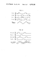
- FIGS. 5A, 5B, 6A, 6B, 7A, 7B, 8A and 8B The locus of the magnetic field upon starting and stopping rotation thereof as well as waveforms of the x-coil current I x and the y-coil current I y are illustrated in FIGS. 5A, 5B, 6A, 6B, 7A, 7B, 8A and 8B.
- FIGS. 5A and 5B correspond to the first method mentioned above
- FIGS. 6A and 6B, 7A and 7B, and 8A and 8B correspond, respectively, to the second, third and the fourth methods mentioned above.
- the triangular waveforms of the driving current are illustrated in FIGS. 5A to 8B, it will be appreciated that the loci (circular and octagonal loci) of the rotating magnetic field can be generated in correspondence to sinusoidal and trapezoidal waveforms of the driving current, respectively.
- FIG. 9 is a view for illustrating characteristically an error free time T F (i.e. averaged time interval at which error is produced in a single bubble memory element or a single chip) as a function of intensity of the inplane D.C. field H DCY when the bubble element is driven in accordance with the driving methods of the four varieties mentioned above and according to the ordinary method illustrated in FIG. 4C (i.e., rotation of the magnetic field is instantly stopped when it comes in a predetermined direction in which it is to be stopped).
- T F i.e. averaged time interval at which error is produced in a single bubble memory element or a single chip
- curves (a) to (d) correspond, respectively, the first to fourth methods illustrated in FIGS. 5A and 5B, 6A and 6B, 7A and 7B, and 8A and 8B, while a curve (e) corresponds to the ordinary driving method (illustrated in FIG. 4C).
- the error free time T F is increased as the value of the inplane D.C. field H DCY is increased. Accordingly, by setting the inplane D.C. field H DCY at a sufficiently large value, the error free time T F can assume a practically sufficiently large value.
- the value of the inplane D.C. field H DCY can not be set at an adequately large value due to restriction imposed by structural factors of the memory module. More specifically, intensity of the inplane D.C. field is limited within a range of 5 to 6 Oe. Further, in consideration of variation or ununiformity in the structure as well as characteristics of the memory modules, it is desirable from the practical viewpoint that a sufficiently long error free time can be realized at the intensity of the inplane D.C. field on the order of 4 Oe.
- the relationship between the error free time T F and an angle by which angle the rotating magnetic field is made to rotate beyond or overrun the direction in which it is to be finally stopped for a given value (e.g. 4 Oe) of the inplane D.C. magnetic field H DCY is examined in the fourth driving method illustrated in FIGS. 8A and 8B, and 6(d), to thereby determine the conditions which allow the error free time T F to be increased.
- rotation of the magnetic field is finally stopped or removed after allowing the magnetic field to rotate beyond a predetermined direction in which it is to be finally stopped by an angle in a range of 10° to 40° and then rotating back the rotating magnetic field until it comes in the predetermined direction, to thereby realize an increased error free time with the inplane D.C. magnetic field H DCY of a practically realizable range.
- FIGS. 1A to 1C are views for illustrating, respectively, a circular path, an octagonal path and a square path of a rotating magnetic field, by way of example;
- FIG. 2 is a view showing an exemplary driving coil arrangement including an x-coil and a y-coil;
- FIGS. 3A to 3C are views for illustrating waveforms of drive currents (I x , I y ) supplied to the x-coil and the y-coil, respectively;
- FIGS. 4A to 4C are views for illustrating the paths of the rotating magnetic fields, respectively, at the time of stoppage of rotation of the magnetic fields in hitherto known magnetic bubble memory devices;
- FIGS. 5A, 5B, 6A, 6B, 7A, 7B, 8A and 8B are views for illustrating paths followed by the rotating magnetic fields upon stoppage thereof according to hitherto known methods of preventing the erroneous operation of the bubble memory device;
- FIG. 9 is a view for illustrating graphically a relationship between the inplane D.C. magnetic field (H DCY ) and the error free time (T F );
- FIG. 10 is a view showing a rotating magnetic field drive circuit used in the invention.
- FIG. 11 is a view for illustrating a waveform of the driving current which can be generated by the rotating magnetic field drive circuit shown in FIG. 10 together with transistor ON/OFF signals;
- FIG. 12 is a view for illustrating the waveform of the driving currents produced by a pair of the rotating magnetic field driving circuits shown in FIG. 10 incorporating the x-coil and the y-coil, respectively, when driven in accordance with the prior art method;
- FIG. 13 is a view for illustrating a driving current waveform generated according to an embodiment of the invention.
- FIG. 14 is a view for illustrating a path followed by a rotating magnetic field produced through the driving current illustrated in FIG. 10;
- FIG. 15 is a view for illustrating a relationship between the error free time (T F ) and an angle ( ⁇ ) representative of over-rotation of the magnetic field in a magnetic bubble memory device driven by the current of the waveform illustrated in FIG. 13;
- FIG. 16 is a view for illustrating waveform of a driving current generated according to another embodiment of the present invention.
- FIG. 17 is a view for illustrating the path followed by a rotating magnetic field produced through the driving current illustrated in FIG. 13;
- FIG. 18 is a view for illustrating a relationship between the over-rotation angle ( ⁇ ) and the error free time (T F ) in the embodiment illustrated in FIG. 13;
- FIGS. 19A and 19B are views for illustrating a path of a rotating magnetic field produced according to further embodiments of the invention applied to a sinusoidal current drive system.
- FIGS. 20A and 20B are views for illustrating a path of a rotating magnetic field produced by a trapezoidal current drive system according to still further embodiments of the invention.
- FIG. 10 is a circuit diagram showing a rotating magnetic field driving circuit used in carrying out the invention.
- reference numeral 8 denotes a coil
- 9 to 12 denote transistors
- 13 to 20 denote diodes
- 21 denotes a power supply source.
- a pair of the circuits each shown in FIG. 10 are employed, wherein the x-coil shown in FIG. 2 is connected as the coil 8 in one of the circuits while the y-coil shown in FIG. 2 is connected as the coil 8 in the other circuit.
- the transistors constituting parts of the x-coil drive circuit are denoted by 9 to 12 with those of the y-coil drive circuit being denoted by 9' to 12', respectively.
- the control illustrated in FIG. 12 corresponds to the ordinary field stopping method described hereinbefore by referring to FIG. 4C. More specifically, when the x-coil current I x returns to zero from a positive peak, operation of the x-coil drive circuit is stopped. On the other hand, when the y-coil current returns to zero from a positive peak, operation of the y-coil drive circuit is stopped.
- FIG. 13 is a diagram illustrating a waveform of the coil driving currents produced according to an embodiment of the invention
- FIG. 14 shows a locus of a rotating magnetic field generated through the current of the waveform illustrated in FIG. 13.
- the transistors 10 and 11 are turned on for a period which is longer than 0% of the period of the rotating magnetic field and shorter than 12.5% thereof, to thereby cause a current 22 of a triangular waveform having a narrow width and a small amplitude to flow through the x-coil in the negative direction after the x-coil current I x returns to zero from the positive peak.
- the y-coil drive current I y is of the same waveform as illustrated in FIG. 12.
- a rotating magnetic field which follows a square path shown in FIG. 14 is generated. More specifically, the rotating magnetic field once rotates beyond the (+)y-axis (corresponding to the direction in which the rotation is to be stopped) and subsequently turns at a right angle toward the (+)y-axis to reach the origin (the state of zero field).
- the error free time T F is more than 10 5 seconds which is longer by a factor of 10 or more when compared with the error free time given by the relation represented by the curve (e) in FIG. 9.
- the error free time T F becomes close to a value of 10 7 seconds, assuring excellently improved characteristic.
- the over-rotation angle ⁇ in a range of 10 to 40 degrees when the rotating magnetic field which follows the path shown in FIG. 14 is employed, there can be obtained preferable characteristic. More preferably, the over-rotation angle ⁇ should be in a range of 15 to 35 degrees.
- FIG. 16 illustrates a waveform of the coil drive currents according to another embodiment of the invention
- FIG. 17 is a diagram showing a path followed by the rotating magnetic field as generated.
- the transistors 10 and 11 are turned on for a period longer than 0% of the period of the rotating magnetic field and not longer than 25% thereof, when the x-coil current I x returns to zero after having attained a positive peak, whereby a negative current of a triangular waveform is caused to flow through the x-coil. Additionally, the transistor 12' is turned on in a manner illustrated in FIG. 16 at Tr.12', to thereby stretch correspondingly the y-coil current I y .
- the rotating magnetic field generated in this way follows a path shown in FIG. 17. More specifically, the path extends once beyond the (+)y-axis substantially in parallel with the (-)x-axis and then returns toward the (+)y-axis to reach ultimately the origin.
- FIG. 18 graphically shows a relationship between the over-rotation angle ⁇ shown in FIG. 17 and the error free time T F on the assumption that inplane D.C. field H DCY is 4 Oe.
- the error free time T F assumes a value in a range of 10 8 to 10 9 seconds, assuring a remarkable improvement over the prior art.
- the error free time T F is about 20 to 30 times as high as that of the first embodiment, meaning significant improvement over the latter.
- FIGS. 19A and 19B illustrate driving methods in which the drive current of a sinusoidal waveform is employed.
- the rotating magnetic field overruns once the (+)y-axis (stop direction) and turns at a right angle relative to the circular path toward the (+)y-axis to ultimately reach the origin.
- the rotating field once overruns the (+)y-axis and turns toward the latter substantially along the circular path to ultimately reach the origin.
- the over-rotation angle ⁇ is in a range of 10 to 40 degrees.
- FIGS. 20A and 20B show driving methods in which the drive current of a trapezoidal waveform is employed.
- the magnetic field rotating along an octagonal path overruns once the (+)y-axis and turns at a right angle toward the (+)y-axis to finally reach the origin.
- the magnetic field rotating along an octagonal path overruns once the (+)y-axis and returns toward the (+)y-axis following substantially along the path along which the magnetic field has just overrun the (+)y-axis, to finally reach the origin.
- the over-rotation angle ⁇ is in a range of 10 to 40 degrees.
Landscapes
- Electromagnets (AREA)
- Magnetic Resonance Imaging Apparatus (AREA)
Abstract
Description
Claims (8)
Priority Applications (1)
| Application Number | Priority Date | Filing Date | Title |
|---|---|---|---|
| ES539034A ES8801160A1 (en) | 1984-02-08 | 1984-12-24 | Apparatus for manually supplying stretch plastic film |
Applications Claiming Priority (2)
| Application Number | Priority Date | Filing Date | Title |
|---|---|---|---|
| JP58-141230 | 1983-08-03 | ||
| JP58141230A JPS6032198A (en) | 1983-08-03 | 1983-08-03 | Magnetic bubble memory device |
Publications (1)
| Publication Number | Publication Date |
|---|---|
| US4550388A true US4550388A (en) | 1985-10-29 |
Family
ID=15287132
Family Applications (1)
| Application Number | Title | Priority Date | Filing Date |
|---|---|---|---|
| US06/636,671 Expired - Lifetime US4550388A (en) | 1983-08-03 | 1984-08-01 | Method of controlling stop operation of rotating magnetic field for magnetic bubble memory device |
Country Status (3)
| Country | Link |
|---|---|
| US (1) | US4550388A (en) |
| JP (1) | JPS6032198A (en) |
| GB (1) | GB2145886B (en) |
Citations (10)
| Publication number | Priority date | Publication date | Assignee | Title |
|---|---|---|---|---|
| JPS4924650A (en) * | 1972-06-30 | 1974-03-05 | ||
| JPS4988438A (en) * | 1972-12-25 | 1974-08-23 | ||
| JPS5092647A (en) * | 1973-12-14 | 1975-07-24 | ||
| JPS5130442A (en) * | 1974-09-09 | 1976-03-15 | Hitachi Ltd | |
| JPS5313842A (en) * | 1976-07-23 | 1978-02-07 | Hitachi Ltd | Magnetic bubble unit of start stop type |
| JPS54125935A (en) * | 1978-03-24 | 1979-09-29 | Hitachi Ltd | Driving circuit for magnetic bubble memory |
| JPS55122288A (en) * | 1979-03-14 | 1980-09-19 | Nec Corp | Magnetic bubble rotating magnetic field driving circuit |
| JPS5758281A (en) * | 1980-09-24 | 1982-04-07 | Hitachi Ltd | Magnetic bubble memory device |
| JPS57131685A (en) * | 1981-02-03 | 1982-08-14 | Mitsubishi Electric Corp | Cage door device for oblique travelling elevator |
| JPS5812190A (en) * | 1981-07-15 | 1983-01-24 | Hitachi Ltd | Magnetic bubble memory device |
-
1983
- 1983-08-03 JP JP58141230A patent/JPS6032198A/en active Pending
-
1984
- 1984-08-01 GB GB08419622A patent/GB2145886B/en not_active Expired
- 1984-08-01 US US06/636,671 patent/US4550388A/en not_active Expired - Lifetime
Patent Citations (10)
| Publication number | Priority date | Publication date | Assignee | Title |
|---|---|---|---|---|
| JPS4924650A (en) * | 1972-06-30 | 1974-03-05 | ||
| JPS4988438A (en) * | 1972-12-25 | 1974-08-23 | ||
| JPS5092647A (en) * | 1973-12-14 | 1975-07-24 | ||
| JPS5130442A (en) * | 1974-09-09 | 1976-03-15 | Hitachi Ltd | |
| JPS5313842A (en) * | 1976-07-23 | 1978-02-07 | Hitachi Ltd | Magnetic bubble unit of start stop type |
| JPS54125935A (en) * | 1978-03-24 | 1979-09-29 | Hitachi Ltd | Driving circuit for magnetic bubble memory |
| JPS55122288A (en) * | 1979-03-14 | 1980-09-19 | Nec Corp | Magnetic bubble rotating magnetic field driving circuit |
| JPS5758281A (en) * | 1980-09-24 | 1982-04-07 | Hitachi Ltd | Magnetic bubble memory device |
| JPS57131685A (en) * | 1981-02-03 | 1982-08-14 | Mitsubishi Electric Corp | Cage door device for oblique travelling elevator |
| JPS5812190A (en) * | 1981-07-15 | 1983-01-24 | Hitachi Ltd | Magnetic bubble memory device |
Also Published As
| Publication number | Publication date |
|---|---|
| GB2145886B (en) | 1986-09-10 |
| GB2145886A (en) | 1985-04-03 |
| JPS6032198A (en) | 1985-02-19 |
| GB8419622D0 (en) | 1984-09-05 |
Similar Documents
| Publication | Publication Date | Title |
|---|---|---|
| US5703451A (en) | Motor driving circuit | |
| EP0833439B1 (en) | Synchronous driving method for inductive load and synchronous controller for h-bridge circuit | |
| JP4729165B2 (en) | Backward-driveable MOS output driver | |
| JPH0126279B2 (en) | ||
| EP0540275B1 (en) | A circuit apparatus for driving a magnetic head | |
| US4550388A (en) | Method of controlling stop operation of rotating magnetic field for magnetic bubble memory device | |
| EP0151354A3 (en) | Programmable read-only memory devices (PROM) | |
| US4145750A (en) | Field access magnetic bubble memory device | |
| EP0068306B1 (en) | Step motor drive circuit | |
| JPH05268769A (en) | H-bridge reset recirculation circuit | |
| JPS6223060Y2 (en) | ||
| JPH02132916A (en) | Inductive load driving circuit | |
| EP0527641B1 (en) | H-bridge flyback recirculator | |
| KR920005037B1 (en) | Automatic Focused Motor Drive Circuit System Using Pulse Width Modulation | |
| KR100486354B1 (en) | Output circuit for motor driving integrated circuit | |
| US4247911A (en) | Drive circuit for magnetic bubble device | |
| JP2884886B2 (en) | Reset circuit in superconducting memory circuit | |
| JPH066629Y2 (en) | Switching circuit | |
| KR960008002Y1 (en) | Bias circuit of high freq. amp | |
| JPS592112B2 (en) | Magnetic bubble chip tape carrier mounting structure | |
| JPH05713B2 (en) | ||
| JPS597153B2 (en) | magnetic bubble drive device | |
| JPS59126323A (en) | Relay driving circuit | |
| JPH09252591A (en) | Power supply apparatus of driving circuit | |
| JPH0537326A (en) | Load drive circuit gate control method |
Legal Events
| Date | Code | Title | Description |
|---|---|---|---|
| AS | Assignment |
Owner name: HITACHI MICROCOMPUTER ENGINEERING LTD., 1479 JOSU Free format text: ASSIGNMENT OF ASSIGNORS INTEREST.;ASSIGNORS:TOYOOKA, TAKASHI;YOSHIDA, KAZUTOSHI;ISHIDA, KAZUHIRO;AND OTHERS;REEL/FRAME:004294/0448 Effective date: 19840723 Owner name: HITACHI, LTD., 6,KANDA SURUGADAI 4-CHOME CHIYODA-K Free format text: ASSIGNMENT OF ASSIGNORS INTEREST.;ASSIGNORS:TOYOOKA, TAKASHI;YOSHIDA, KAZUTOSHI;ISHIDA, KAZUHIRO;AND OTHERS;REEL/FRAME:004294/0448 Effective date: 19840723 |
|
| STCF | Information on status: patent grant |
Free format text: PATENTED CASE |
|
| FEPP | Fee payment procedure |
Free format text: PAYOR NUMBER ASSIGNED (ORIGINAL EVENT CODE: ASPN); ENTITY STATUS OF PATENT OWNER: LARGE ENTITY |
|
| FPAY | Fee payment |
Year of fee payment: 4 |
|
| FPAY | Fee payment |
Year of fee payment: 8 |
|
| FPAY | Fee payment |
Year of fee payment: 12 |