US4497302A - Fuel control apparatus for internal combustion engine - Google Patents
Fuel control apparatus for internal combustion engine Download PDFInfo
- Publication number
- US4497302A US4497302A US06/471,127 US47112783A US4497302A US 4497302 A US4497302 A US 4497302A US 47112783 A US47112783 A US 47112783A US 4497302 A US4497302 A US 4497302A
- Authority
- US
- United States
- Prior art keywords
- fuel
- engine
- control apparatus
- time
- air
- Prior art date
- Legal status (The legal status is an assumption and is not a legal conclusion. Google has not performed a legal analysis and makes no representation as to the accuracy of the status listed.)
- Expired - Fee Related
Links
- 239000000446 fuel Substances 0.000 title claims abstract description 122
- 238000002485 combustion reaction Methods 0.000 title claims abstract description 27
- 238000002347 injection Methods 0.000 claims abstract description 40
- 239000007924 injection Substances 0.000 claims abstract description 40
- 239000007789 gas Substances 0.000 claims description 14
- QVGXLLKOCUKJST-UHFFFAOYSA-N atomic oxygen Chemical compound [O] QVGXLLKOCUKJST-UHFFFAOYSA-N 0.000 claims description 11
- 239000001301 oxygen Substances 0.000 claims description 11
- 229910052760 oxygen Inorganic materials 0.000 claims description 11
- 239000000203 mixture Substances 0.000 abstract description 9
- 230000004044 response Effects 0.000 abstract description 9
- 238000000034 method Methods 0.000 description 17
- 238000005070 sampling Methods 0.000 description 6
- 230000001133 acceleration Effects 0.000 description 4
- 239000000498 cooling water Substances 0.000 description 4
- 238000006243 chemical reaction Methods 0.000 description 3
- 238000010586 diagram Methods 0.000 description 3
- 230000006870 function Effects 0.000 description 3
- YWXYYJSYQOXTPL-SLPGGIOYSA-N isosorbide mononitrate Chemical compound [O-][N+](=O)O[C@@H]1CO[C@@H]2[C@@H](O)CO[C@@H]21 YWXYYJSYQOXTPL-SLPGGIOYSA-N 0.000 description 3
- 230000003111 delayed effect Effects 0.000 description 2
- 239000002828 fuel tank Substances 0.000 description 2
- 230000005764 inhibitory process Effects 0.000 description 2
- RVTZCBVAJQQJTK-UHFFFAOYSA-N oxygen(2-);zirconium(4+) Chemical compound [O-2].[O-2].[Zr+4] RVTZCBVAJQQJTK-UHFFFAOYSA-N 0.000 description 2
- 230000003252 repetitive effect Effects 0.000 description 2
- XLYOFNOQVPJJNP-UHFFFAOYSA-N water Substances O XLYOFNOQVPJJNP-UHFFFAOYSA-N 0.000 description 2
- 229910001928 zirconium oxide Inorganic materials 0.000 description 2
- 241000478345 Afer Species 0.000 description 1
- 230000033228 biological regulation Effects 0.000 description 1
- 239000000567 combustion gas Substances 0.000 description 1
- 238000011109 contamination Methods 0.000 description 1
- 239000000428 dust Substances 0.000 description 1
- 238000001914 filtration Methods 0.000 description 1
- 239000012530 fluid Substances 0.000 description 1
- 239000000463 material Substances 0.000 description 1
- 230000000063 preceeding effect Effects 0.000 description 1
- 238000000746 purification Methods 0.000 description 1
- 239000007784 solid electrolyte Substances 0.000 description 1
- 239000007858 starting material Substances 0.000 description 1
- 230000001052 transient effect Effects 0.000 description 1
- 238000011144 upstream manufacturing Methods 0.000 description 1
- 239000002699 waste material Substances 0.000 description 1
Images


Classifications
-
- F—MECHANICAL ENGINEERING; LIGHTING; HEATING; WEAPONS; BLASTING
- F02—COMBUSTION ENGINES; HOT-GAS OR COMBUSTION-PRODUCT ENGINE PLANTS
- F02D—CONTROLLING COMBUSTION ENGINES
- F02D41/00—Electrical control of supply of combustible mixture or its constituents
- F02D41/02—Circuit arrangements for generating control signals
- F02D41/14—Introducing closed-loop corrections
- F02D41/1438—Introducing closed-loop corrections using means for determining characteristics of the combustion gases; Sensors therefor
- F02D41/1477—Introducing closed-loop corrections using means for determining characteristics of the combustion gases; Sensors therefor characterised by the regulation circuit or part of it,(e.g. comparator, PI regulator, output)
- F02D41/1481—Using a delaying circuit
-
- F—MECHANICAL ENGINEERING; LIGHTING; HEATING; WEAPONS; BLASTING
- F02—COMBUSTION ENGINES; HOT-GAS OR COMBUSTION-PRODUCT ENGINE PLANTS
- F02D—CONTROLLING COMBUSTION ENGINES
- F02D41/00—Electrical control of supply of combustible mixture or its constituents
- F02D41/02—Circuit arrangements for generating control signals
- F02D41/18—Circuit arrangements for generating control signals by measuring intake air flow
- F02D41/187—Circuit arrangements for generating control signals by measuring intake air flow using a hot wire flow sensor
-
- F—MECHANICAL ENGINEERING; LIGHTING; HEATING; WEAPONS; BLASTING
- F02—COMBUSTION ENGINES; HOT-GAS OR COMBUSTION-PRODUCT ENGINE PLANTS
- F02D—CONTROLLING COMBUSTION ENGINES
- F02D41/00—Electrical control of supply of combustible mixture or its constituents
- F02D41/30—Controlling fuel injection
- F02D41/32—Controlling fuel injection of the low pressure type
- F02D41/34—Controlling fuel injection of the low pressure type with means for controlling injection timing or duration
- F02D41/345—Controlling injection timing
-
- Y—GENERAL TAGGING OF NEW TECHNOLOGICAL DEVELOPMENTS; GENERAL TAGGING OF CROSS-SECTIONAL TECHNOLOGIES SPANNING OVER SEVERAL SECTIONS OF THE IPC; TECHNICAL SUBJECTS COVERED BY FORMER USPC CROSS-REFERENCE ART COLLECTIONS [XRACs] AND DIGESTS
- Y02—TECHNOLOGIES OR APPLICATIONS FOR MITIGATION OR ADAPTATION AGAINST CLIMATE CHANGE
- Y02T—CLIMATE CHANGE MITIGATION TECHNOLOGIES RELATED TO TRANSPORTATION
- Y02T10/00—Road transport of goods or passengers
- Y02T10/10—Internal combustion engine [ICE] based vehicles
- Y02T10/40—Engine management systems
Definitions
- This invention relates to fuel control apparatus for internal combustion engine, and, more particularly, to a fuel injection control apparatus for internal combustion engine capable of correcting for a response lag in a fuel suction path.
- a conventional fuel control apparatus for internal combustion engine has a sensor, responsive to a particular exhaust gas concentration in the exhaust pipe, to produce a signal, which is fed back to the fuel injection control apparatus to thereby control the air-fuel ratio.
- a solid electrolyte such as, for example, zirconium oxide is used to detect partial pressure of oxygen in the exhaust gases and the air-fuel ratio is controlled to be a stoichiometric equilibrium point (hereinafter, called the theoretical air-fuel ratio).
- an exhaust sensor oxygen or O 2
- an air-fuel ratio adjusting device acts to increase or decrease the air-fuel ratio at a uniform rate with time and the switching between the increase and decrease is made when the output of the oxygen sensor has crossed the reference level.
- the device when the sensor changes its output from lean-fuel level to rich-fuel level, the device adjusts to decrease the air-fuel ratio, and when it changes its output from rich-fuel level to lean-fuel level, the device adjusts to increase the ratio. Because of such adjustment, the engine actually wastes time upon feeding fuel and air from fuel supply device to combustion chamber.
- the air-fuel ratio at which the mixture of fuel and air is actually burnt in the combustion chamber has a phase lag shown in FIG. 1C, corresponding to wasted or dead time on the intake side when the adjustment is made as shown in FIG. 1B.
- the peaks of the wave of FIG. 1C show excessive values over the average value thereof. The large peak increases harmful components in the exhaust gases and brings about instability in driving.
- the air-fuel ratio is determined from the partial pressure of oxygen in the exhaust gases afer combustion, a response lag is caused to trouble general feed-back control, and dead time is taken in association with the intake pipe, combustion and exhausting. Consequently, the increase of loop gain in control system causes hunting in the air-fuel ratio and hence brings about an extremely unstable combustion state to increase harmful exhaust gases.
- the decrease of loop gain makes the response of the system very slow, causing long transient conditions unsatisfactory for the internal combustion engine.
- the air-fuel ratio is fluctuated with the result that harmful exhaust gases are increased. Therefore, it is necessary to increase the loop gain to limit at which no hunting is caused.
- lag time of system and dead time are fluctuated to a great extent depending on the driving condition of engine, and thus makes it difficult to set up a proper gain.
- the fact that the dead time is fluctuated to a great extent depending on the operating condition of the engine means that a time duration from the time when fuel is injected by an injector to the time when the injected fuel is reached to the combustion chamber of a corresponding cylinder through the fuel intake path is fluctuated to a great extent depending on the operating condition of the engine.
- the fuel injection timing is not controlled by considering such fluctuations of the dead time, and hence the conventional fuel control apparatus has a disadvantage that a desired fuel amount cannot necessarily be supplied into the combustion chamber when the engine operating condition is changed, whereby by the fuel control can not precisely be carried out.
- dead time in the total distance of a known system is calculated from the output of a hot wire flow sensor, or the flow rate of intake air, and the amount of adjustment delayed by that dead time is sampled upon level change of output from the oxygen sensor to be used as a reference to control.
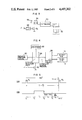
- FIGS. 1A, 1B and 1C are explanatory diagrams useful for explaining the conventional fuel control method
- FIG. 2 is a partial cross-sectional view of an engine control system
- FIG. 3 is a schematic view of the ignition device in FIG. 2;
- FIG. 4 is a diagram of an exhaust gas recirculation system
- FIG. 5 is a fuel injection timing chart for a fluid control apparatus of the present invention.
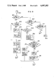
- FIG. 6 is a diagram of control system for an engine
- FIG. 7 is a specific flowchart of the control system of FIG. 6;
- FIG. 8 is a timing chart of sampling the output voltage from hot wire of a sensor
- FIG. 9 is a flowchart of INTL interrupt process for sampling the signal from the hot wire flow sensor
- FIG. 10 is a flowchart of air amount signal processing task
- FIG. 11 is a flowchart of fuel injection control task
- FIG. 12 shows a generator for interrupt IRQ.
- sucked air is fed to a cylinder 8 through an air cleaner 2, a throttle chamber 4, and an intake pipe 6.
- the combustion gas in the cylinder 8 is exhausted to the air through an exhaust pipe 10.
- the oxygen concentration of the exhaust gases is detected by an O 2 sensor 11.
- a fuel injector 12 is provided in the throttle chamber 4, with the fuel injector 12 being adapted to inject fuel which is then atomized within the passage of throttle chamber 4 through which air is drawn and, as a result, a mixture of fuel and drawn in air is formed and then fed through an intake pipe 6 and through an open intake valve 20, to the combustion chamber of the cylinder 8.
- Throttle valves 14 and 16 are provided near the outlet of the injector 12, with the throttle valve 14 being constructed to be mechanically connected to the accelerator pedal which the operator drives.
- the throttle valve 16 is so arranged as to be driven by a diaphragm 18 and, when the amount of air flow is small, the valve 16 is completely closed, and as the air flow increases, the negative pressure on the diaphragm 18 increases to gradually open the valve 16, preventing an increase in the suction resistance.
- An air-flow passage 22 is provided above the throttle valves 14 and 16 in the throttle chamber 4, with an electric heater 24, forming a hot-wire type air-flow meter, responsive to the rate of the air flow to produce an electric signal which is determined by the relation between the rate of air flow and the amount of heat from the heater 24, being disposed in the air flow passage 22. Since the heater 24 is provided in the air-flow passage 22, it can be protected from the high-temperature gas produced upon a back fire in the cylinder 8 and prevented from the contamination by dust and the like in the drawn in air.
- the air-flow passage 22 has its outlet near the narrowest portion of the venturi tube and its inlet on the upstream side thereof.
- the fuel in the fuel injector 12 is fed from a fuel tank 30 to a fuel-pressure regulator 38 through a fuel pump 32, a fuel damper 34 and a filter 36.
- the fuel pressure regulator 38 supplies fuel under pressure to the injector 12 through a pipe 40 and also feeds fuel back to the fuel tank 30 through a return pipe 42 in order that the difference between the pressure in the intake pipe 6 into which fuel is injected from the injection 12, and the pressure of the fuel fed to the injector 12 can be maintained constant.
- the mixture of fuel and air drawn through the intake valve 20 is compressed by a piston 50 and then burnt by sparking of an ignition plug 52.
- the combustion of the mixture is converted to a kinetic energy.
- the cylinder 8 is cooled by cooling water 54 and the resulting temperature of the used cooling water is measured by a water temperature sensor 56 and used as the engine temperature.
- the ignition plug 52 is supplied with a high voltage from an ignition coil 58 in synchronism with the ignition operation.
- crankshaft (not shown) is provided with a crank angle sensor which generates a reference angle signal and a position signal at every reference crank angle and at every constant angle (for example, 0.5 degrees) as the engine rotates, respectively.
- the electric signals from the output of this crank angle sensor, outputs of the water temperature sensor 56 and heater 24 are supplied to a control circuit 64 formed of a microcomputer or the like and arithmetically processed by the control circuit 64, the output of which is used to drive the fuel injector 12 and ignition coil 58.
- a bypass 26 communicating with the intake pipe 6 is provided over the throttle valve 16 in the throttle chamber 4, and this bypass 26 is provided with a bypass valve 62 to be controlled to open and close.
- the drive portion of this bypass valve 62 is supplied with a signal from the control circuit 64 so that the valve 62 is controlled to open and close.
- the bypass valve 62 faces to the bypass 26 going around the throttle valve 16 and is controlled to open and close by a pulse current.
- This bypass valve 62 changes the cross-sectional area of the bypass 26 in response to the amount that the valve is lifted by the output of the control circuit 64 through the driving system. That is, the control circuit 64 generates an open/close period signal for controlling the driving system to supply a control signal to the drive portion of the bypass valve 62 thereby adjusting the amount of lifting the bypass valve 62.
- a pulse current is supplied through an amplifier 68 to a power transistor 72 to make it conductive. Consequently, current flows through the primary of an ignition coil 68 from a battery 66 and, when this pulse current falls off, the transistor 72 is nonconductive and hence a high voltage is induced in the secondary of the ignition coil 58. This induced high voltage is distributed to each of the ignition plugs 52 which is disposed in each cylinder of the engine, in synchronism with the rotation of engine.
- a constant negative pressure from a negative pressure source 80 is exerted through a pressure control valve 84 onto a control valve 86.
- the pressure control valve 84 controls the constant negative pressure of the negative pressure source 80 to be divided into partial pressures on the atmosphere 88 and the control valve 86, the ratio of which is controlled in accordance with the duty ratio of the repetitive pulse applied to the pressure control valve 84 from a transistor 90.
- the negative pressure applied on the control valve 86 is determined by the on-duty ratio of the pulse from the transistor 90.
- the controlled negative pressure from the valve 84 controls the amount of EGR from the exhaust pipe 10 to the intake pipe 6.
- a waveform of reference angle pulses R 1 and R 2 is shown wherein each of the pulses R 1 , R 2 is produced at every predetermined reference crank angle, 180° in this case.
- T i represents the fuel injection period.
- Time t 3 is the closing time of the intake valve 20 of the corresponding cylinder.
- the valve closing angle is fixed at a predetermined crank angle ⁇ from the reference postion where the reference pulse R 2 is produced.
- a time duration t D from time t 2 to time t 3 represents the dead time described above.
- the finally injected fuel injected at time t 2 is delivered in the intake pipe 6 and passed through the intake valve 20 at time t 3 , at which the intake valve 20 is closed.
- the dead time t D fluctuates to a great extent depending on the engine operating condition.
- the beginning time (t 1 ) of the fuel injection is altered in accordance with the fluctuations of the dead time t D , almost all of the fuel injected during the period T i is surely supplied into the combustion chamber in the form of air-fuel mixture under any operating conditions of the engine, whereby accurate fuel control can be effected.
- the mixture is supplied into the combustion chamber at appropriate timing, a stratified charge of mixture enriching toward the spark plug side is formed in the combustion chamber. By this stratified charge good combustion of the mixture is obtained which contributes exhaust gas purification.
- the dead time t D can be obtained from the following equation:
- the beginning time t 1 of the fuel injection is determined as a time point preceeding from the occurrence of the reference angle pulse R 2 by the total of the fuel injection duration T i , the dead time duration t D and the time duration t 74 .
- the beginning time t 1 is determined by calculating a time duration t after the occurrence of the reference angle signal R 1 which preceeds the injection, according to the following equation: ##EQU1##
- time t 3 coincides with the intake valve closing time in FIG. 5, it is not limited to the valve closing time, but may be a time point related to the valve closing time, say near to the intake valve closing time. Further, time t 3 may be variable in accordance with a particular characteristic of engines. Where the manifold length L 1 is considerably different depending on the cylinders of a multi-cylinder engine, two or more dead times may be employed.
- the control system comprises a CPU 102, a read-only memory (hereinafter, referred to as ROM) 104, a random access memory (hereinafter, referred to as RAM) 106 and an input/output unit 108.
- the CPU 102 arithmetically processes the input data from the input/output unit 108 and returns the results to the unit 108 in accordance with various programs stored in the ROM 104.
- the RAM 106 serves to store all intermediate results of this computation.
- Bus lines 110 which comprises a data but, a control bus and an address bus, interconnect the CPU 102, ROM 104, RAM 106 and input/output unit 108 to carry various kinds of data therebetween.
- the input/output unit 108 comprises a first analog-to-digital converter (hereinafter, referred to as ADC1), a second analog-to-digital converter (hereinafter, referred to as ADC2), an angle signal processing circuit 126, and a discrete input/output circuit for 1-bit, information hereinafter, referred to as DIO).
- ADC1 first analog-to-digital converter
- ADC2 second analog-to-digital converter
- DIO discrete input/output circuit for 1-bit, information hereinafter, referred to as DIO
- the ADC1 includes: a multiplexer (hereinafter, referred to as MPX) 120 which is supplied with the outputs from a battery voltage detecting sensor 132 (VBS), a cooling water temperature sensor 56 (TWS), an atmosphere temperature sensor 112 (TAS), a regulation voltage generator 114 (VRS), a throttle angle sensor 116 ( ⁇ THS), and a ⁇ sensor 118 ( ⁇ S); an analog-to-digital converter 122 (ADC) to which one of the outputs is applied from the MPX 120: and a register 124 (REG) which holds the digital value from the ADC.
- MPX multiplexer
- the ADC2 includes an analog-to-digital converter 128 (ADC) which is supplied with the output from a flow sensor 24 (AFS), and a register 130 (REG) in which the output of the ADC is set.
- ADC analog-to-digital converter 128
- ADC analog-to-digital converter 128
- FAS flow sensor 24
- REG register 130
- An angle sensor 146 produces a signal of a reference crank angle, for example, 180 degrees (REF) and a signal indicative of a very small angle, for example, 0.5-degree crank angle (POS) and supplied them to an angle signal processing circuit 126, where they are shaped in their waveforms.
- a reference crank angle for example, 180 degrees (REF)
- POS 0.5-degree crank angle
- the DIO is supplied with the outputs from an idle switch 148 (IDLE-SW), a top gear switch 150 (TOP-SW) and a starter switch 152 (START-SW).
- ILE-SW idle switch 148
- TOP-SW top gear switch 150
- STT-SW starter switch 152
- An injector control circuit 134 converts the digital values of the calculated results to a pulse output.
- the INJC 134 generates a pulse of the width corresponding to the amount of fuel injection and supplies it through an AND gate 136 to the fuel injector 12.
- An ignition pulse generator 138 comprises a register (ADV) for storing the ignition time and a register (DWL) for storing the time the primary current starts to flow through the primary of the ignition coil.
- the CPU 102 sets such data in the ADV and DWL of the IGNC 138.
- the pulse based on the data is supplied from the IGNC 138 through an AND gate 140 to the amplifier 68.
- the degree to which the bypass valve 62 opens is controlled by the pulse applied from a control circuit (ISCC) 142 through an AND gate 144.
- the ISCC 142 has a register (ISCD) for storing the pulse width and a register (ISCP) for storing the period of the repetitive pulse.
- An EGR amount control pulse generator 154 which permits the transistor 90 to control the EGR control valve 86 shown in FIG. 3, comprises a register EGRD for storing the duty ratio of the pulse and a register EGRP for storing the period of the pulse.
- the output pulse from the EGRC 154 is applied through an AND gate 156 to the transistor 90.
- the input/output signal of 1 bit is controlled by the circuit DIO.
- the input signals thereto are the IDLE-SW, TOP-SW, and START-SW signals as described above.
- the output signal is a pulse output signal for driving the fuel pump.
- the DIO includes a register DDR for determining whether its terminals are used as input or output terminals, and a register DOUT for latching the output data.
- a register 160 is a register (MOD) for holding an instruction to take various conditions within the input/output circuit 108.
- the AND gates 136, 140, 144 and 156 can all be turned on or off by setting an instruction in this register.
- the INJC 134, IGNC 138 and ISCC 142 can be controlled to stop or produce output by setting an instruction in the MOD register 160.
- the operating system program OS comprises the initial processing program 202, the interruption processing program 206, the task dispatcher 208 and the macro processing program 228.
- the interruption processing program 206 includes various different interruption programs.
- initial interruption program (INTL interruption processing) 602
- initial interrupt is caused half-the-number-of-engine-cylinders times, or two times per engine revolution for 4 cylinder engine, by the initial interrupt signal produced in synchronism with engine rotation.
- the fuel injection time calculated at EGI, task 612 is set up in the EGI register of the input/output interface circuit 108.
- An A/D conversion interrupt process 604 includes two types: A/D converter-1 interrupt (ADC1) and A/D converter-2 interrupt (ADC2).
- A/D converter-1 has precision of 8 bits and is supplied with source voltage, cooling water temperature, sucked air temperature, adjustment of engine and so on.
- this A/D converter-1 specifies one of such inputs to the multiplexer 120 and at the same time starts to convert. After completion of the conversion, it produces ADC1 interrupt, which is used only before cranking.
- the A/D converter 128 is supplied with an air flow input, and ADC2 interrupt is produced after end of conversion. This interrupt is also used only before cranking.
- an INTV interrupt signal is produced for example, at every 10 ms set up in an INTV register and used as a time monitor fundamental signal for task to be started with a constant period. This interrupt signal is used to update the software timer, and permits the task reached a specified time period to start.
- an engine stop interrupt processing program (ENST interrupt processing program) 608 which detects the condition of engine stop, counting starts when the INTL interrupt signal is detected, and then an ENST interrupt occurs when the next INTL interrupt signal cannot be detected within a predetermined time, for example, 1 second.
- the task group started by the different interrupts mentioned before is as follows: amount-of-air-signal processing task (AS task), fuel injection control task (EGI task) and initial monitor task (MONIT task) for task level 0; AD1 input task (ADIN1 task), and time coefficient processing task (AFSIA task) for task level 1; and idle speed control task (ISC task), compensation calculation task (HOSEI task) and initial preprocess task (ISTRT task) for task level 2.
- AS task amount-of-air-signal processing task
- EGI task fuel injection control task
- MONIT task initial monitor task
- AD1 input task AD1 input task
- AFSIA task time coefficient processing task
- ISC task idle speed control task
- HOSEI task compensation calculation task
- ISTRT task initial preprocess task
- Table 2 shows assignment of each task level and task functions.
- the start periods of the tasks to be started by different interrupts are predetermined as is evident from Table 2, and stored in ROM 104.
- the INTL interrupt process will be described which is one example of processing signals v from the hotwire flow sensor.
- the signals v from tht hot-wire flow sensor are received by the INTL interruption at different timing for three modes of the revolution speed of engine. That is, as shown in FIG. 8, the revolution speed N of 4-cylinder engine is smaller than 1600 rpm for mode 0, is in the range from 1600 rpm to 3200 rpm, inclusive for mode 1, and is larger than 3200 rpm for mode 2. Thus, one intake stroke corresponds to a crank rotation angle of 180°. In this embodiment, the N is 1600 rpm for mode 0, 3200 rpm for mode 1 and 6400 rpm for mode 2. Thus, the engine in mode 1 rotates through twice the angle in mode 0 and in mode 2 rotates through four times the angle in mode 0. or twice the angle in mode 1 as shown in FIG. 8.
- in mode 0 sampling is mode at each 18° of crank rotation angle
- in mode 1 sampling is made at each 36° of crank angle because the revolution speed N is twice that in mode 0
- in mode 2 sampling is made at each 72° of crank angle because the revolution speed N is four times that in mode 0. Therefore, at a crank rotation angle per intake stroke, the same amount of data as in mode 0 is sampled in each mode. If the interval of sampling data is changed in proportion to the revolution speed of engine, the data processing time is constant regardless of change of revolution speed.
- step 801 decision is made of whether an INTL interrupt occurred or not. If the decision is YES, the program goes to step 802, where decision is made of whether the counter for counting the number of receiving times of analog value u (hereinafter referred to as analog counter) is at zero or not. If the decision is YES, the program further goes to step 803, where the A/D converter is started to introduce the amount of air u. When the amount of air, u begins to be drawn in, the program progresses to step 804, where the timer is set at a time when the next amount of air u drawn in, in accordance with the revolution speed of engine and the mode thereof.
- analog counter the number of receiving times of analog value u
- step 804 When at step 804 the timer is set, the program goes to step 805, where EGIREG, IGNREG are set. At step 806, the interrupt for only INTLIRQ is released from inhibition. Then, the INTL interrupt processing program ends. If at step 802 the analog counter is not at zero, the program goes to step 805.
- step 801 If at step 801 no INTL interrupt occurs, the program goes to step 807, where decision is made of whether it is the timer interrupt for QA or not. If the decision is YES, the program goes to step 808, where decision is made of whether the timer interrupt inhibit flag is set or not. If the decision is YES, the program ends. If it is NO, the program goes to step 809, where the amount of aif, u is introduced so that the analog counter is incremented by 1. At step 810, decision is made of whether the suction of u has been completed or not (whether the contents of the analog counter shows a specified number of times that the suction occurs). If the decision is YES, the program goes to step 811, where the timer is stopped. Then, at step 812 the analog counter is reset.
- step 810 the suction is not completed, the program goes to step 813, where the A/D converter 128 is started. Then, at step 814, u 2 is calculated and stored in RAM.
- step 807 If at step 807 the interrupt is decided not to be timer interrupt, the program goes to step 815, where decision is made of whether or not it is ADC interrupt. If at step 815 the decision is YES, the program is returned from the interrupt. If at step 815 it is not AD interrupt or at step 816 IST is not 1, the program goes to the INTV interrupt process 606 in FIG. 7.
- the task of amount-of-air signal process (AC) 610 as shown in FIG. 7 will hereinafter be described.
- the amount-of-air signal process task is started at step 901 as shown in FIG. 10.
- the program goes to step 902, where u-suction inhibit flag is set.
- (u 2 ) 2 is calculated to obtain the value of an air flow amount (Q A ) and stored in RAM, since the output (u) of a hot-wire type air-flow sensor is directly proportional to the fourth root of the air flow amount (Q A ).
- the suction inhibit flag is reset.
- the program goes to step 905, where the value (u 2 ) 2 stored in RAM at step 903 is accumulated and averaged.
- step 906 injection timing considering fuel transport lag or dead time t D is calculated from 1/Q A and revolution speed N of engine as described previously.
- decision is made of whether or not it shows acceleration state of engine. If at step 907 the decision is YES, the program goes to step 908, where acceleration injection is made. If at step 907 it is NO, the program goes to the macro process 228 in FIG. 7 after acceleration injection at step 908.
- the fuel injection control task is started at step 950, then, at step 951, a basic fuel injection time t i is calculated from average amount of air Q A and revolution speed N of engine. Then, at step 954, decision is made of whether or not the signal from the oxygen sensor (O 2 sensor) has crossed the theoretical air-fuel ratio. If at step 954 the decision is YES, the program goes to step 955, where an air-fuel ratio correction coefficient ⁇ ix at the time when the theoretical air-fuel ratio is determined from the reciprocal, 1/Q A of the average air amount, is read from the RAM as ⁇ i . If at step 954 the decision is NO, the program goes to step 952.
- a fuel injection time T i is calculated by multiplying the basic fuel injection time t i by an air-fuel ratio correction coefficient ⁇ i .
- the air-fuel ratio correction coefficient ⁇ i is stored in RAM.
- the fuel injection time T i is stored in a register. Then, the program progresses to the macro process 228 in FIG. 7.
- FIG. 12 shows a generator circuit for IRQ.
- a register 735, counter 736, comparator 737 and flip-flop 738 constitute a generator circuit for INTV IRQ.
- the register 735 is set the period of INTV IRQ to be generated, for example, in this embodiment, 10 ms.
- a clock pulse is set in the counter 736 and, when its count reaches the contents of the register 735, it sets the flip-flop 738. At this time, the counter 736 is cleared and again starts to count. Therefore, the INTV IRQ is generated at intervals of constant time (10 msec).
- a register 741, counter 742, comparator 743, and flip-flop 744 constitute a generator circuit for ENST IRQ by which engine stop is detected.
- the comparator 743 sets the flip-flop 744, thus ENST IRQ being generated therefrom.
- the REF pulse is generated at intervals of constant crank angle from the crank angle sensor during engine rotation, to clear the counter 742, which thus does not reach the contents of the register 741 so that no ENST IRQ is generated.
- the INTV IRQ generated from the flip-flop 738, ENST IRQ from the flip-flop 744, and IRQs from the ADC1 and ADC2 are respectively set in flip-flops 740, 746, 764, and 768.
- a signal for permitting the IRQ to be produced or not is set in flip-flops 739, 745, 762 and 766. If "H" level is set in the flip-flops 739, 745, 762 and 766, AND gates 748, 750, 770 and 772 are gated open. At this time, when IRQ is generated, it readily appears from an OR gate 751.
- the IRQ can be inhibited from generation or released from the inhibition by supplying "H” or "L” level to each of the flip-flops 739, 745, 762 and 766.
- the contents of the flip-flops 740, 746, 764 and 768 is supplied to the CPU, which thus can find the cause of IRQ generation.
- the IRQ signal is required to be cleared, and thus the CPU clears the corresponding one of the flip-flops 740, 746, 764 and 768 to that IRQ.
- the amount of control upon level change can be controlled to achieve the theoretical air-fuel ratio, and in addition, for deviation to exceeding rich or lean concentration of fuel, modifying amount of control is always added to cancel the deviation out. Therefore, unlike the prior art, the control for excessively rich concentration of fuel is made to effectively decrease the concentration. Also, since the loop gain can be increased for the same hunting limit, the control gain is increased to decrease harmful exhaust gas and achieve the stability of operation of engine.
- the control apparatus according to this invention as described above is able to stabilize the fuel injection of internal combustion engine and increase response.
Landscapes
- Engineering & Computer Science (AREA)
- Chemical & Material Sciences (AREA)
- Combustion & Propulsion (AREA)
- Mechanical Engineering (AREA)
- General Engineering & Computer Science (AREA)
- Electrical Control Of Air Or Fuel Supplied To Internal-Combustion Engine (AREA)
Applications Claiming Priority (2)
| Application Number | Priority Date | Filing Date | Title |
|---|---|---|---|
| JP57032361A JPS58150047A (ja) | 1982-03-03 | 1982-03-03 | 内燃機関の燃料噴射制御装置 |
| JP47-32361 | 1982-03-03 |
Publications (1)
| Publication Number | Publication Date |
|---|---|
| US4497302A true US4497302A (en) | 1985-02-05 |
Family
ID=12356812
Family Applications (1)
| Application Number | Title | Priority Date | Filing Date |
|---|---|---|---|
| US06/471,127 Expired - Fee Related US4497302A (en) | 1982-03-03 | 1983-03-01 | Fuel control apparatus for internal combustion engine |
Country Status (4)
| Country | Link |
|---|---|
| US (1) | US4497302A (de) |
| EP (1) | EP0087802B1 (de) |
| JP (1) | JPS58150047A (de) |
| DE (1) | DE3378921D1 (de) |
Cited By (2)
| Publication number | Priority date | Publication date | Assignee | Title |
|---|---|---|---|---|
| DE4209163A1 (de) * | 1992-03-20 | 1993-09-23 | Bayerische Motoren Werke Ag | Gemischbildungs-verfahren fuer gemischverdichtende, fremdgezuendete brennkraftmaschinen |
| US5925089A (en) * | 1996-07-10 | 1999-07-20 | Yamaha Hatsudoki Kabushiki Kaisha | Model-based control method and apparatus using inverse model |
Families Citing this family (1)
| Publication number | Priority date | Publication date | Assignee | Title |
|---|---|---|---|---|
| WO2013103018A1 (ja) * | 2012-01-06 | 2013-07-11 | トヨタ自動車株式会社 | 内燃機関の吸入空気量計測装置 |
Citations (12)
| Publication number | Priority date | Publication date | Assignee | Title |
|---|---|---|---|---|
| US4123999A (en) * | 1975-10-28 | 1978-11-07 | Nissan Motor Company, Ltd. | Feedback air-fuel ratio control system for internal combustion engine capable of providing constant control signal at start of fuel feed |
| US4130095A (en) * | 1977-07-12 | 1978-12-19 | General Motors Corporation | Fuel control system with calibration learning capability for motor vehicle internal combustion engine |
| US4131091A (en) * | 1975-10-27 | 1978-12-26 | Nissan Motor Company, Ltd. | Variable gain closed-loop control apparatus for internal combustion engines |
| US4187806A (en) * | 1976-05-22 | 1980-02-12 | Robert Bosch Gmbh | Fuel-air mixture control apparatus |
| US4210106A (en) * | 1975-10-13 | 1980-07-01 | Robert Bosch Gmbh | Method and apparatus for regulating a combustible mixture |
| US4228775A (en) * | 1978-11-17 | 1980-10-21 | General Motors Corporation | Closed loop air/fuel ratio controller with asymmetrical proportional term |
| US4244340A (en) * | 1975-04-18 | 1981-01-13 | Robert Bosch Gmbh | Method and apparatus for controlling fuel management for an internal combustion engine |
| US4278060A (en) * | 1978-05-02 | 1981-07-14 | Toyota Jidosha Kogyo Kabushiki Kaisha | Feedback type air fuel ratio controlling system |
| US4282842A (en) * | 1977-07-22 | 1981-08-11 | Hitachi, Ltd. | Fuel supply control system for internal combustion engine |
| US4350130A (en) * | 1980-08-27 | 1982-09-21 | Ford Motor Company | Air fuel mixture control system and method |
| US4364356A (en) * | 1972-09-06 | 1982-12-21 | Uop Inc. | Exhaust emissions control system |
| US4402293A (en) * | 1980-03-07 | 1983-09-06 | Fuji Jukogyo Kabushiki Kaisha | Air-fuel ratio control system |
Family Cites Families (5)
| Publication number | Priority date | Publication date | Assignee | Title |
|---|---|---|---|---|
| JPS54162022A (en) * | 1978-06-12 | 1979-12-22 | Nippon Denso Co Ltd | Air fuel ratio controller |
| CA1119493A (en) * | 1978-07-21 | 1982-03-09 | Mamoru Fujieda | Fuel injection system for internal combustion engine |
| US4355620A (en) * | 1979-02-08 | 1982-10-26 | Lucas Industries Limited | Fuel system for an internal combustion engine |
| US4235204A (en) * | 1979-04-02 | 1980-11-25 | General Motors Corporation | Fuel control with learning capability for motor vehicle combustion engine |
| JPS582435A (ja) * | 1981-04-20 | 1983-01-08 | Hitachi Ltd | デイ−ゼル機関用電磁弁駆動タイミング制御装置 |
-
1982
- 1982-03-03 JP JP57032361A patent/JPS58150047A/ja active Pending
-
1983
- 1983-03-01 DE DE8383101981T patent/DE3378921D1/de not_active Expired
- 1983-03-01 US US06/471,127 patent/US4497302A/en not_active Expired - Fee Related
- 1983-03-01 EP EP83101981A patent/EP0087802B1/de not_active Expired
Patent Citations (12)
| Publication number | Priority date | Publication date | Assignee | Title |
|---|---|---|---|---|
| US4364356A (en) * | 1972-09-06 | 1982-12-21 | Uop Inc. | Exhaust emissions control system |
| US4244340A (en) * | 1975-04-18 | 1981-01-13 | Robert Bosch Gmbh | Method and apparatus for controlling fuel management for an internal combustion engine |
| US4210106A (en) * | 1975-10-13 | 1980-07-01 | Robert Bosch Gmbh | Method and apparatus for regulating a combustible mixture |
| US4131091A (en) * | 1975-10-27 | 1978-12-26 | Nissan Motor Company, Ltd. | Variable gain closed-loop control apparatus for internal combustion engines |
| US4123999A (en) * | 1975-10-28 | 1978-11-07 | Nissan Motor Company, Ltd. | Feedback air-fuel ratio control system for internal combustion engine capable of providing constant control signal at start of fuel feed |
| US4187806A (en) * | 1976-05-22 | 1980-02-12 | Robert Bosch Gmbh | Fuel-air mixture control apparatus |
| US4130095A (en) * | 1977-07-12 | 1978-12-19 | General Motors Corporation | Fuel control system with calibration learning capability for motor vehicle internal combustion engine |
| US4282842A (en) * | 1977-07-22 | 1981-08-11 | Hitachi, Ltd. | Fuel supply control system for internal combustion engine |
| US4278060A (en) * | 1978-05-02 | 1981-07-14 | Toyota Jidosha Kogyo Kabushiki Kaisha | Feedback type air fuel ratio controlling system |
| US4228775A (en) * | 1978-11-17 | 1980-10-21 | General Motors Corporation | Closed loop air/fuel ratio controller with asymmetrical proportional term |
| US4402293A (en) * | 1980-03-07 | 1983-09-06 | Fuji Jukogyo Kabushiki Kaisha | Air-fuel ratio control system |
| US4350130A (en) * | 1980-08-27 | 1982-09-21 | Ford Motor Company | Air fuel mixture control system and method |
Cited By (3)
| Publication number | Priority date | Publication date | Assignee | Title |
|---|---|---|---|---|
| DE4209163A1 (de) * | 1992-03-20 | 1993-09-23 | Bayerische Motoren Werke Ag | Gemischbildungs-verfahren fuer gemischverdichtende, fremdgezuendete brennkraftmaschinen |
| DE4209163B4 (de) * | 1992-03-20 | 2009-09-17 | Bayerische Motoren Werke Aktiengesellschaft | Gemischbildungs-Verfahren für gemischverdichtende, fremdgezündete Brennkraftmaschinen |
| US5925089A (en) * | 1996-07-10 | 1999-07-20 | Yamaha Hatsudoki Kabushiki Kaisha | Model-based control method and apparatus using inverse model |
Also Published As
| Publication number | Publication date |
|---|---|
| DE3378921D1 (en) | 1989-02-16 |
| EP0087802A2 (de) | 1983-09-07 |
| EP0087802B1 (de) | 1989-01-11 |
| EP0087802A3 (en) | 1985-08-14 |
| JPS58150047A (ja) | 1983-09-06 |
Similar Documents
| Publication | Publication Date | Title |
|---|---|---|
| US4630206A (en) | Method of fuel injection into engine | |
| US5278762A (en) | Engine control apparatus using exhaust gas temperature to control fuel mixture and spark timing | |
| EP0046305B1 (de) | Verfahren und Vorrichtung zum Steuern eines Verbrennungsmotors | |
| US4561401A (en) | Air-fuel ratio control system | |
| JP2518717B2 (ja) | 内燃機関の冷却装置 | |
| US4523284A (en) | Method of controlling internal combustion engine | |
| US5226390A (en) | Apparatus for controlling variation in torque of internal combustion engine | |
| US4455980A (en) | Engine combustion control method | |
| JPH0526936B2 (de) | ||
| US5664544A (en) | Apparatus and method for control of an internal combustion engine | |
| US4498445A (en) | Air/fuel ratio feedback control system adapted to obtain stable engine operation under particular engine operating conditions | |
| KR880001665B1 (ko) | 연료분사제어장치 | |
| US4542729A (en) | Air/fuel ratio control method having fail-safe function for abnormalities in oxygen concentration detecting means for internal combustion engines | |
| US4681077A (en) | Air-fuel ratio controlling method and apparatus for an internal combustion engine | |
| US4497302A (en) | Fuel control apparatus for internal combustion engine | |
| KR920003200B1 (ko) | 엔진제어장치 | |
| EP0106366B1 (de) | Steuermethode für Brennkraftmaschine | |
| US4528964A (en) | Fuel injection control apparatus for internal combustion engine | |
| US4706632A (en) | Fuel control apparatus for internal combustion engine | |
| US4961411A (en) | Fuel control apparatus | |
| KR920003201B1 (ko) | 내연기관용 연료분사장치 | |
| JPH0452382B2 (de) | ||
| JPH02104932A (ja) | エンジン制御装置 | |
| US4522178A (en) | Method of fuel control in engine | |
| EP0296323B1 (de) | Motorsteuerungsmethode |
Legal Events
| Date | Code | Title | Description |
|---|---|---|---|
| AS | Assignment |
Owner name: HITACHI, LTD.,5-1, MARUNOUCHI 1-CHOME, CHIYODA-KU, Free format text: ASSIGNMENT OF ASSIGNORS INTEREST.;ASSIGNORS:SASAYAMA, TAKAO;AMANO, MATSUO;REEL/FRAME:004102/0650 Effective date: 19830215 |
|
| FPAY | Fee payment |
Year of fee payment: 4 |
|
| FPAY | Fee payment |
Year of fee payment: 8 |
|
| REMI | Maintenance fee reminder mailed | ||
| LAPS | Lapse for failure to pay maintenance fees | ||
| FP | Lapsed due to failure to pay maintenance fee |
Effective date: 19970205 |
|
| STCH | Information on status: patent discontinuation |
Free format text: PATENT EXPIRED DUE TO NONPAYMENT OF MAINTENANCE FEES UNDER 37 CFR 1.362 |