US4492524A - Multiple piston pump with a constant discharge capacity - Google Patents
Multiple piston pump with a constant discharge capacity Download PDFInfo
- Publication number
- US4492524A US4492524A US06/303,057 US30305781A US4492524A US 4492524 A US4492524 A US 4492524A US 30305781 A US30305781 A US 30305781A US 4492524 A US4492524 A US 4492524A
- Authority
- US
- United States
- Prior art keywords
- frequency
- speed
- pulses
- switchable
- pulse
- Prior art date
- Legal status (The legal status is an assumption and is not a legal conclusion. Google has not performed a legal analysis and makes no representation as to the accuracy of the status listed.)
- Expired - Fee Related
Links
- 239000007788 liquid Substances 0.000 claims abstract description 64
- 230000001105 regulatory effect Effects 0.000 claims abstract description 36
- 238000006073 displacement reaction Methods 0.000 claims abstract description 9
- 230000008859 change Effects 0.000 claims description 12
- 230000001965 increasing effect Effects 0.000 claims description 12
- 230000004044 response Effects 0.000 claims description 11
- 230000009467 reduction Effects 0.000 claims description 9
- 238000012544 monitoring process Methods 0.000 claims description 7
- 230000005540 biological transmission Effects 0.000 claims description 5
- 230000007774 longterm Effects 0.000 claims description 5
- 230000010349 pulsation Effects 0.000 claims 15
- 238000012806 monitoring device Methods 0.000 claims 6
- 238000005086 pumping Methods 0.000 claims 3
- 230000006835 compression Effects 0.000 description 11
- 238000007906 compression Methods 0.000 description 11
- 238000010276 construction Methods 0.000 description 10
- 230000001419 dependent effect Effects 0.000 description 5
- 238000010586 diagram Methods 0.000 description 3
- 238000004458 analytical method Methods 0.000 description 2
- 238000004811 liquid chromatography Methods 0.000 description 2
- 239000000203 mixture Substances 0.000 description 2
- 239000000700 radioactive tracer Substances 0.000 description 2
- 238000012935 Averaging Methods 0.000 description 1
- 230000008901 benefit Effects 0.000 description 1
- 230000000694 effects Effects 0.000 description 1
- 239000012530 fluid Substances 0.000 description 1
- 238000009499 grossing Methods 0.000 description 1
- 230000001939 inductive effect Effects 0.000 description 1
- 238000004519 manufacturing process Methods 0.000 description 1
- 238000005259 measurement Methods 0.000 description 1
- 238000000034 method Methods 0.000 description 1
- 238000001208 nuclear magnetic resonance pulse sequence Methods 0.000 description 1
- 230000003287 optical effect Effects 0.000 description 1
- 239000011877 solvent mixture Substances 0.000 description 1
- 230000007704 transition Effects 0.000 description 1
Images


Classifications
-
- G—PHYSICS
- G01—MEASURING; TESTING
- G01N—INVESTIGATING OR ANALYSING MATERIALS BY DETERMINING THEIR CHEMICAL OR PHYSICAL PROPERTIES
- G01N30/00—Investigating or analysing materials by separation into components using adsorption, absorption or similar phenomena or using ion-exchange, e.g. chromatography or field flow fractionation
- G01N30/02—Column chromatography
- G01N30/26—Conditioning of the fluid carrier; Flow patterns
- G01N30/28—Control of physical parameters of the fluid carrier
- G01N30/32—Control of physical parameters of the fluid carrier of pressure or speed
-
- F—MECHANICAL ENGINEERING; LIGHTING; HEATING; WEAPONS; BLASTING
- F04—POSITIVE - DISPLACEMENT MACHINES FOR LIQUIDS; PUMPS FOR LIQUIDS OR ELASTIC FLUIDS
- F04B—POSITIVE-DISPLACEMENT MACHINES FOR LIQUIDS; PUMPS
- F04B49/00—Control, e.g. of pump delivery, or pump pressure of, or safety measures for, machines, pumps, or pumping installations, not otherwise provided for, or of interest apart from, groups F04B1/00 - F04B47/00
- F04B49/20—Control, e.g. of pump delivery, or pump pressure of, or safety measures for, machines, pumps, or pumping installations, not otherwise provided for, or of interest apart from, groups F04B1/00 - F04B47/00 by changing the driving speed
-
- G—PHYSICS
- G01—MEASURING; TESTING
- G01N—INVESTIGATING OR ANALYSING MATERIALS BY DETERMINING THEIR CHEMICAL OR PHYSICAL PROPERTIES
- G01N30/00—Investigating or analysing materials by separation into components using adsorption, absorption or similar phenomena or using ion-exchange, e.g. chromatography or field flow fractionation
- G01N30/02—Column chromatography
- G01N30/26—Conditioning of the fluid carrier; Flow patterns
- G01N30/28—Control of physical parameters of the fluid carrier
- G01N30/32—Control of physical parameters of the fluid carrier of pressure or speed
- G01N2030/326—Control of physical parameters of the fluid carrier of pressure or speed pumps
Definitions
- the invention relates to a multiple pump with a constant discharge capacity for liquid chromatographs, whereof the drive comprises a motor and a regulating system responding to the pressure of the liquid conveyed for changing the speed of the motor and consequently the discharge capacity depending on the liquid pressure.
- the pressures to be employed in this case are in the order of magnitude of several hundred Bars with a discharge capacity of up to 10 ml/min. With a pressure in the order of magnitude of several hundred Bars, an appreciable compression of the liquid occurs.
- German OS No. 23 11 016 discloses a multiple piston pump of the aforementioned type, which comprises two piston-cylinder units, which are driven by a motor with the interposition of a transmission comprising gears constructed in an elliptical manner and arranged eccentrically so that the sum of the respective piston displacements of both cylinders in the compression direction is equal to a constant, so that the piston pump has a constant discharge capacity on account of its mechanical construction.
- the regulating system responding to the pressure of the liquid conveyed serves to vary the speed of the motor in the case of a charge in the pressure so that variations in the rate of delivery caused by the compression of the liquid are compensated for and the rate of delivery remains constant even with changes of pressure.
- the constant discharge capacity depends on its mechanical construction. This construction must be carried out with extremely high accuracy, in order to ensure a constant discharge capacity in the case of small discharge capacities. Furthermore, the manufacture and assembly of elliptical and eccentric gears involves considerable difficulties.
- the piston pump comprises at least three piston-cylinder units, whereof the pistons are driven through a non-linear drive by the motor with a mutual phase displacement of 360°/n, when n represents the number of piston-cylinder units and the regulating system is designed for the variation of the speed of the motor during each period or cycle of the piston movement to compensate for the non-linear drive so that the pressure of the liquid conveyed remains at least approximately constant during each period or cycle.
- a multiple piston pump according to the invention could also be constructed with more than three piston-cylinder units.
- the construction of a control loop is not appreciably influenced and each additional piston-cylinder unit involves expenditure, at present a pump with three piston-cylinder units is regarded as optimum.
- a speed regulation of the motor takes place in such a manner that the pressure of the liquid conveyed remains constant.
- the pressure of the liquid conveyed depends not only on the discharge capacity, but also on the viscosity of the liquid conveyed. If the viscosity of the liquid conveyed increases, then with a constant discharge capacity, the pressure in the liquid conveyed increases. Accordingly, when the pressure is kept constant, any change in the viscosity of the liquid conveyed results in a change in the discharge capacity.
- liquid chromatography one frequently works with solvent mixtures, whose composition is changed within the course of an analysis, so that the viscosity of the liquid conveyed also changes in the course of an analysis.
- the regulating system comprises a device which is not pressure-dependent for monitoring the mean speed of the motor and for keeping it constant. Since in piston pumps, the speed of the motor is a direct measurement of the discharge capacity, the discharge capacity also remains constant if the mean speed is kept constant. Then, the sole purpose of the pressure-dependent regulation is to determine the variation of the speed of the motor, which is identified when monitoring the mean speed.
- the regulating system may comprise a device for varying the speed of the motor depending on the mean pressure of the liquid conveyed so that the delivery rate remains constant due to compensation of the pressure-dependent compression of the liquid.
- This device for varying the speed can basically be constructed as described in the above mentioned German OS No. 23 11 016. However, it is more advantageous if the device for varying the speed comprises a sensor responding to the pressure prevailing within at least one of the piston-cylinder units and varies the speed of the motor depending on the distance covered by the piston from its bottom dead centre until the build-up of the operating pressure. The pressure in the piston-cylinder unit must build-up from the pressure of the flowing medium to the discharge pressure and then remain constant until the end of the compression stroke.
- the transition from the pressure rise to constant pressure can be monitored by measuring techniques so that in this way the travel of the piston until the build-up of the operating pressure can be ascertained and depending thereon the discharge capacity of the pump can be compensated, without data relating to the compressibility of various liquids having to be available as a function of the operating pressure.
- the motor for driving the piston pump is constructed as a stepping motor, which is supplied with current pulses whereof the frequency determines the speed of the motor.
- the regulating system is then constructed in order to influence the frequency of the current pulses.
- stepping motors one revolution of the motor is divided into a very large number of steps, so that due to the variation of the pulse frequency and thus of the chronological sequence of the individual steps, a very fine regulation of the speed of the motor is possible during each period of the piston movement.
- Influencing the frequency of the current pulses is then particularly simple if the current pulses for the motor are produced by a driver responding to control pulses and a pulse source is available which supplies control pulses at a frequency which is higher than the frequency which corresponds to the reference speed of the motor and provided between the pulse source and the driver is a controllable frequency divider to which a pressure-dependent control signal is supplied, which adjusts the divider ratio of the frequency divider to values such that the control pulses supplied to the driver have frequencies which are alternately higher and lower than the frequency corresponding to the reference speed. It will be understood that these frequency variations can be random and of different magnitude and can also vary as regards time.
- the frequency corresponding to the reference speed amounts to two thirds the frequency of the control pulses supplied by the pulse source and the frequency divider can be set to the divider ratios 1:1 and 1:2.
- a regulating system operating under such conditions can be produced at extremely low cost.
- the regulating system comprises an electrical pressure convertor responding to the pressure of the liquid conveyed, the output signal of which convertor is supplied by way of a high-pass filter and an adding stage, in which the output signal is superimposed on a reference direct voltage, to a threshold value discriminator, whereof the output signal controls the adjustment of the frequency divider.
- the reference direct voltage determines the mean speed of the motor, whereas owing to the use of a high-pass filter, only those components of the signal, which the electrical pressure convertor supplies, are taken into consideration, which can be traced back to rapid pressure fluctuations and therefore serve for the variation of the speed of the motor during each period of the piston movement.
- the reference direct voltage may be a control voltage derived from the speed of the motor.
- this control voltage may be characteristic of the difference between the frequency corresponding to the reference speed and the mean frequency of the control pulses supplied to the driver and may bring about a reduction of this difference.
- a first pulse signal characteristic of the frequency corresponding to the reference speed can be supplied to one input and a second pulse signal characteristic of the instantaneous frequency of the control pulses supplied to the driver can be supplied to the outer input of a forwards-backwards counter, so that the counting state is always equal to the difference between the pulses supplied by both pulse signals.
- the control voltage used as the reference direct voltage may then be an analog voltage derived from the respective counting state.
- the frequency corresponding to the reference speed amounts to two thirds of the frequency of the control pulses supplied by the pulse source and the freqency divider can be set to the divider ratios 1:1 and 1:2, then advantageously the first pulse signal can be formed by a uniform pulse sequence, whereof the frequency is equal to one third of the frequency of the control pulses supplied by the pulse source and when set to the divider ratio 1:2, the frequency divider supplies every other control pulse to the counter as a second pulse signal, instead of to the driver.
- the above mentioned device for varying the speed depending on the pressure of the medium, which serves to equalize the compression of the liquid, can in a particularly simple manner bring about a pressure-dependent variation of the frequency of the control pulses supplied by the pulse source.
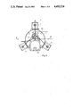
- FIG. 1 is a view of a multiple piston pump according to the invention
- FIG. 2 is a view of the pump according to FIG. 1 in the direction of arrow II,
- FIG. 3 is a diagrammatic section on line III--III through the pump according to FIG. 2 and
- FIG. 4 is the block circuit diagram of the regulating system of the pump illustrated as an embodiment.
- the piston pump illustrated in FIGS. 1 to 3 comprises three piston-cylinder units 1 to 3, which are flange-mounted on the surface of a cylindrical casing.
- the three piston-cylinder units 1 to 3 have the same construction and consist respectively, as shown in detail in FIG. 3 for the piston-cylinder unit 1, of a cylinder block 5 and a plunger 6, whereof the front end of reduced diameter forms the piston 7.
- the piston 7 projects into a thin cylinder bore 8 of the cylinder block 5 and is sealed at its rear end with respect to the cylinder block by a seal 9 shown only diagrammatically. Opening into the cylinder bore 8 is a radial bore 10, to which an inlet pipe 11 is connected.
- a non-return valve 12 Located between the inlet pipe 11 and the radial bore 10 is a non-return valve 12, which blocks the feed pipe 11 during the delivery stroke of the piston.
- the pipe 14 containing the medium conveyed is connected to a second radial bore 13.
- a non-return valve 15 is located between the radial bore 13 and the outlet pipe 14, which non-return valve blocks the pipe 14 during the suction stroke of the pump.
- a sensor 16 Located at the end of the cylinder bore 8 is a sensor 16, which produces an electrical signal proportional to the pressure prevailing in the cylinder and supplies it on a lead 17 to the microprocessor 18 of the regulating system (FIG. 4).
- a stepping motor 23 Serving to drive the plunger 6 of the piston-cylinder unit 1 as well as the plungers 21 and 22 of the piston-cylinder units 2 and 3 is a stepping motor 23, which is fastened to an end wall of the casing 4. Its drive shaft 24 projects into the casing 4 and supports a gear 25, which meshes with a gear 26 of larger diameter mounted in the casing 4. Mounted eccentrically on the same shaft 27 as this gear 26 is a cam disc 28, on the periphery of which the plungers 6, 21 and 22 are seated by their ends. In order to reduce the friction, a ring 29 mounted to rotate on the periphery of the cam disc 28 can be provided between the cam disc 28 and the ends of the plungers 6,21 and 22.
- the plungers 6,21 and 22 are respectively acted upon by a compression spring 30,31,32 which is supported at one end against the surface of the casing 4 and at the other end against a flange or collar 33, 34,35 located on the plunger. Since the three plungers 6,21 and 22 are off set at an angle of 120° with respect to each other, radially with respect to the shaft 27 supporting the cam disc 28 and cooperate with the same cam disc 28, they carry out their movements controlled by the cam disc 28, with a phase displacement of 120° with respect to each other. Furthermore, with this arrangement, the position of the pistons is a direct function of the position of the gear 26 driving the cam disc 28.
- the teeth of the gear can be utilized at the same time as a digital transmitter for ascertaining its angular position and thus for determining the piston positions.
- the teeth can be scanned by suitable optical or electrical means, for example by means of an inductive tracer 36, as shown diagrammatically in FIG. 3.
- the signals produced by the tracer 36 are supplied by means of a lead 37 leaving the casing 4 likewise to the microprocessor 18 (FIG. 4).
- the supply pipes 11 of the three cylinder-piston units 1 to 3 lead to a distributor 38, from which a pipe 39 leads to the medium to be conveyed.
- the outlet pipes 14 are connected to a distributor 40, from which a common high pressure pipe 41 leads to the column of a liquid chromatograph.
- a pressure convertor 42 is Also connected to this distributor 40, whereof the signal characteristic of the pressure prevailing is supplied by way of a lead 43 to a high-pass filter 44 of the regulating system.
- the pressure convertor 42 may also be a piezo-electric component.
- the pressure convertor 42 sends a signal which is characteristic of the pressure in the entire stream, which is formed from the addition of the streams conveyed by the three piston-cylinder units in the distributor 40. This pressure is substantially proportional to the instantaneous total discharge rate of the liquid, which is supplied to the chromatographic column of the analytical instrument having a very high flow resistance.
- the speed of the stepping motor 23 is determined by the frequency of the current pulses, with which it is supplied, because the rotor of the stepping motor is rotated by each current pulse stepwise by a certain angular amount. For example, one revolution of the motor can be divided into 500 steps.
- the current pulses required for operating the stepping motor are produced by a driver 60, which responds to control pulses and in addition to the necessary power amplifiers comprises a de-coder or fixed store (not shown in detail), which upon the arrival of a control pulse, respectively initiates a set of for example five phase-shifted current pulses necessary for driving the stepping motor.
- the control pulses are supplied by a pulse source 51, which comprises an oscillator 25 and a divider 53, whereof the divider ratio 1:n can be varied in small steps.
- the divider ratio is determined by the output signal of a microprocessor 18, into which a desired speed of the stepping motor 23 or a desired discharge capacity of the pump 54, which is illustrated in the block circuit diagram according to FIG. 4 by the box 54, can be fed by means of an adjustor 55. Then, with the assistance of stored data, the microprocessor determines the divider ratio 1:n of the divider 53, which in turn determines the frequency of the control pulses, which are supplied to the driver 60.
- the control pulses of frequency f supplied accordingly by the pulse source 51 are supplied on the lead 56 to a divider 57, which can be adjusted by means of a switching member 58 to the reduction ratios 1:1 and 1:2.
- the output signal of the divider 57 is supplied to a further divider 59, which reduces the frequency of the control pulses once more in the ratio 1:8, before they are supplied to the driver 60, which supplies the stepping motor 23.
- the frequency f of the control pulses supplied by the pulse source 51 is chosen so that the stepping motor 23 would operate at the desired speed and the pump 54 would have the desired discharge capacity, if the frequency of the control pulses amounted to 2f/3. Therefore, the stepping motor 23 operates too quickly, if the divider 57 does not reduce the frequency f of the control pulses (divider ratio 1:1) and too slowly, if the divider 57 supplies the control pulses at the frequency f/2. Consequently, a pressure rise or a pressure drop occurs in the liquid conveyed by the pump 54, to which the pressure convertor 42 responds and supplies an electrical signal, which is supplied via the lead 43 to the high-pass filter 44.
- the output signal of the high-pass filter 44 is characteristic solely of the fluctuations of the pressure over a period of time and comprises no components characteristic of the mean pressure. Therefore, the output signal of the high-pass filter can be superimposed in a subsequent adding or summing stage 61 on a reference direct voltage, which is coordinated with the response threshold of a Schmitt trigger or bistable threshold value discriminator 62 so that the Schmitt trigger is tripped in the range of positive sections of the signal supplied by the high-pass filter.
- the output signal of the electronic switching member or stage 58 causes a change-over of the divider 57 to the ratio 1:2, so that the speed of the stepping motor 23 and accordingly also the discharge capacity of the pump 54 is reduced.
- the pump operates at a reduced discharge capacity until the signal supplied by the pressure convertor 42 once more falls below the threshold value of the Schmitt trigger, whereupon the output signal of the Schmitt trigger 62 changes in a corresponding manner and causes the switching member 58 to restore the divider 57 to the ratio 1:1.
- the stepping motor 23 again operates at increased speed, so that the discharge capacity of the pump 54 and accordingly also the pressure in the liquid conveyed once more rises until on exceeding the threshold value of the Schmitt trigger 62, the divider 57 again switches back.
- the control loop described has a very simple construction, because it is only necesssary for a divider to be changed from the divider ratio 1:1 to the divider ratio 1:2.
- an arrangement of this type may be provided in that in the divider, every other pulse of the control pulses is suppressed. Above all, due to the use of a divider of this type, the speed jumps are very considerable.
- the use of the additional divider 1:8 brings about averaging, in particular if a change of the reduction ratio occurs frequently, so that the actual speed variations do not take place in the ratio 1:2 or 2:1, but in the ratio (8+k 1 ): (8+k 2 ), if k 1 and k 2 respectively represent a whole number from 0 to 8, which indicates how many of the control pulses of frequency f have been suppressed by the divider 57 in successive counting intervals of the divider 59 as a result of switching-over to the divider ratio 1:2.
- the reference voltage represents a predetermined-mean pressure in the liquid conveyed by the pump 54. Maintaining such a pressure can be advisable as long as the liquid to be conveyed has a constant viscosity. However, if the viscosity of the liquid conveyed varies as a result of long term temperature changes or, however, as a result of a change in the composition of the liquid conveyed, then a change in the delivery pressure is related to this change of viscosity, when the discharge capacity is constant. With a constant discharge capacity, an increase in the viscosity also results in an increase in the pressure and vice versa.
- the regulating system illustrated in FIG. 4 also comprises members for keeping the discharge capacity constant.
- These members comprise a frequency divider 71 connected to the pulse source 51, which divider reduces the control pulses with the frequency f by the ratio 1:3 and a fowards-backwards or up-down counter 72, to which the output signal of the divider 71 is supplied as a first pulse signal and as a second pulse signal, those pulses are supplied by the divider 57, which are suppressed when this divider is adjusted to the divider ratio 1:2.
- the output signal of the 1:3-divider is supplied to the backwards or down counting input and the output signal of the 1:2-divider 57 is supplied to the forwards or up counting input of the counter 72.
- the mean frequency of the control pulses supplied by the divider 57 must amount to 2f/3. This is the case when on average, each third pulse of the control pulses with the frequency f is suppressed by the divider 57, so that these suppressed pulses form a pulse train with the mean frequency f/3.
- the second pulse signal accordingly likewise has the frequency f/3 and the counter 72 stops at a predetermined state, when the divider 57 supplies control pulses to the driver 60, the frequency of which leads to the desired speed of the stepping motor.
- the pressure in the cylinder remains constant.
- the output signal of the sensor 16 is supplied to a micro-processor 18, which responds to the instant at which the pressure passes from the increasing part into the constant part and by means of the signal supplied by the sensor 36 on the lead 37 ascertains how great the stroke of the piston was until the delivery pressure was reached.
- the micro-processor 18 brings about a change in the divider ratio n of the divider 53, in order to increase the frequency f of the control pulses supplied by the pulse source 51 by so much that the delivery volume reduced as a result of the compression is compensated for by an increase in the speed of the stepping motor 23.
- the regulating system itself can be constructed in a different manner, for example due to the increased use of analog or digital components, and also for example due to the omission of the compensation of the liquid compression at high pressures.
- the micro-processor 18 could also be completely dispensed with and the adjustor 55 could be connected directly to the 1:n-divider 53.
Landscapes
- Engineering & Computer Science (AREA)
- General Health & Medical Sciences (AREA)
- Immunology (AREA)
- Chemical & Material Sciences (AREA)
- Analytical Chemistry (AREA)
- Biochemistry (AREA)
- Physics & Mathematics (AREA)
- General Physics & Mathematics (AREA)
- Life Sciences & Earth Sciences (AREA)
- Pathology (AREA)
- Health & Medical Sciences (AREA)
- Mechanical Engineering (AREA)
- General Engineering & Computer Science (AREA)
- Reciprocating Pumps (AREA)
- Control Of Positive-Displacement Pumps (AREA)
Applications Claiming Priority (2)
| Application Number | Priority Date | Filing Date | Title |
|---|---|---|---|
| DE3035770 | 1980-09-23 | ||
| DE3035770A DE3035770C2 (de) | 1980-09-23 | 1980-09-23 | Mehrfach-Kolbenpumpe mit konstanter Förderleistung |
Publications (1)
| Publication Number | Publication Date |
|---|---|
| US4492524A true US4492524A (en) | 1985-01-08 |
Family
ID=6112597
Family Applications (1)
| Application Number | Title | Priority Date | Filing Date |
|---|---|---|---|
| US06/303,057 Expired - Fee Related US4492524A (en) | 1980-09-23 | 1981-09-17 | Multiple piston pump with a constant discharge capacity |
Country Status (6)
| Country | Link |
|---|---|
| US (1) | US4492524A (enExample) |
| JP (1) | JPS5799285A (enExample) |
| CH (1) | CH654074A5 (enExample) |
| DE (1) | DE3035770C2 (enExample) |
| FR (1) | FR2490742A1 (enExample) |
| GB (1) | GB2085980B (enExample) |
Cited By (15)
| Publication number | Priority date | Publication date | Assignee | Title |
|---|---|---|---|---|
| US4595495A (en) * | 1985-02-22 | 1986-06-17 | Eldex Laboratories, Inc. | Programmable solvent delivery system and process |
| US4624625A (en) * | 1981-10-08 | 1986-11-25 | Hewlett-Packard Company | High pressure metering pump |
| US4730992A (en) * | 1986-03-26 | 1988-03-15 | Neuberg Company Limited | Continuously operable hydraulic device |
| US4752385A (en) * | 1985-09-18 | 1988-06-21 | U.S. Philips Corporation | Liquid chromatograph |
| US4767279A (en) * | 1987-06-02 | 1988-08-30 | Millipore Corporation | Fluid composition and volumetric delivery control |
| US4795217A (en) * | 1986-03-07 | 1989-01-03 | Hydro-Ergon Corporation | System for removing material with a high velocity jet of working fluid |
| US4919595A (en) * | 1987-03-03 | 1990-04-24 | Beckman Instruments, Inc. | Fluid delivery system with deficit flow compensation |
| US4980059A (en) * | 1986-09-17 | 1990-12-25 | U.S. Philips Corporation | Liquid chromatograph |
| US20040126243A1 (en) * | 2002-09-23 | 2004-07-01 | Holger Sievert | Method and device for detecting the speed of a pump |
| US20050271525A1 (en) * | 2004-06-03 | 2005-12-08 | Kenji Muramatsu | Pump device |
| KR100888266B1 (ko) * | 2008-05-23 | 2009-03-10 | 천세산업 주식회사 | 등속도 캠을 이용한 3 연식 무맥동 정량펌프 및 제어방법 |
| CN103512986A (zh) * | 2012-06-19 | 2014-01-15 | 道尼克斯索芙特隆公司 | 用于控制针对液相色谱法尤其是高效液相色谱法的活塞泵单元的控制装置 |
| US20170328359A1 (en) * | 2014-11-27 | 2017-11-16 | Provtagaren Ab | Pump control for low flow volumes |
| US10801479B2 (en) | 2011-08-19 | 2020-10-13 | Dionex Softon Gmbh | Device for controlling a piston pump unit for liquid chromatography |
| US11333136B2 (en) * | 2017-11-22 | 2022-05-17 | Aisin Corporation | Fluid pump with cam geometry to reduce pulsations |
Families Citing this family (10)
| Publication number | Priority date | Publication date | Assignee | Title |
|---|---|---|---|---|
| GB2170869B (en) * | 1985-02-12 | 1987-11-11 | Willett Thomas & Co Ltd | Pumping systems |
| GB2195474B (en) * | 1986-09-17 | 1991-01-23 | Philips Electronic Associated | Liquid chromatograph |
| JP2536862B2 (ja) * | 1987-02-28 | 1996-09-25 | 株式会社島津製作所 | マルチ送液ポンプ |
| IT1230274B (it) * | 1989-06-14 | 1991-10-18 | Vitali Spa | Gruppo di comando per presse utilizzate per l'estrazione del burro di cacao, dalla pasta di cacao. |
| DE3943224A1 (de) * | 1989-12-23 | 1991-07-04 | Wissenschaftliche Geraetebau D | Verfahren und vorrichtung zur messung und regelung des ausgangsflusses von schubkolbenpumpen |
| US5108264A (en) * | 1990-08-20 | 1992-04-28 | Hewlett-Packard Company | Method and apparatus for real time compensation of fluid compressibility in high pressure reciprocating pumps |
| DE4029616C2 (de) * | 1990-09-19 | 1994-03-03 | Werner Kellermann | Anlage zum Fördern eines Strömungsmediums |
| FR2817594B1 (fr) * | 2000-12-04 | 2005-07-01 | Exel Ind | Dispositif de pompage pour produits epais ou sensibles a la turbulence |
| JP7119715B2 (ja) * | 2017-11-22 | 2022-08-17 | 株式会社アイシン | 流体ポンプ |
| CN110631758A (zh) * | 2018-06-25 | 2019-12-31 | 中国石油化工股份有限公司 | 一种用于双波纹管差压计的电子驱动装置 |
Citations (12)
| Publication number | Priority date | Publication date | Assignee | Title |
|---|---|---|---|---|
| US3847507A (en) * | 1972-05-17 | 1974-11-12 | Toyo Soda Mfg Co Ltd | Liquid supply system by pump |
| US3882861A (en) * | 1973-09-24 | 1975-05-13 | Vital Assists | Auxiliary control for a blood pump |
| US4028018A (en) * | 1974-06-10 | 1977-06-07 | Paterson Candy International Limited | Non-pulsing apparatus |
| US4173437A (en) * | 1977-08-01 | 1979-11-06 | The Perkin-Elmer Corporation | Dual-piston reciprocating pump assembly |
| US4180375A (en) * | 1977-01-21 | 1979-12-25 | Altex Scientific, Inc. | Liquid chromatography pump |
| US4233156A (en) * | 1978-03-10 | 1980-11-11 | Hitachi, Ltd. | Liquid chromatography apparatus |
| US4255088A (en) * | 1979-06-14 | 1981-03-10 | Valleylab, Inc. | Liquid pumping system having means for detecting gas in the pump |
| US4299541A (en) * | 1977-11-29 | 1981-11-10 | Nikkiso Co., Ltd. | Infusion solution injecting pump |
| US4321014A (en) * | 1979-12-31 | 1982-03-23 | Polaroid Corporation | Constant flow pumping apparatus |
| US4326837A (en) * | 1978-12-15 | 1982-04-27 | Gilson Medical Electronics | Pumping apparatus using a stepping motor |
| US4352636A (en) * | 1980-04-14 | 1982-10-05 | Spectra-Physics, Inc. | Dual piston pump |
| US4359312A (en) * | 1978-08-15 | 1982-11-16 | Zumtobel Kg | Reciprocating pump for the pulsation-free delivery of a liquid |
Family Cites Families (3)
| Publication number | Priority date | Publication date | Assignee | Title |
|---|---|---|---|---|
| US3855129A (en) * | 1972-03-06 | 1974-12-17 | Waters Associates Inc | Novel pumping apparatus |
| US4131393A (en) * | 1977-01-21 | 1978-12-26 | Altex Scientific, Inc. | Fluid pump mechanism |
| DE2823802C2 (de) * | 1978-05-31 | 1982-05-27 | Speidel + Keller Gmbh + Co Kg, 7455 Jungingen | Antriebsanordnung einer oszillierenden Verdrängerpumpe |
-
1980
- 1980-09-23 DE DE3035770A patent/DE3035770C2/de not_active Expired
-
1981
- 1981-09-17 US US06/303,057 patent/US4492524A/en not_active Expired - Fee Related
- 1981-09-21 JP JP56147976A patent/JPS5799285A/ja active Pending
- 1981-09-22 CH CH6111/81A patent/CH654074A5/de not_active IP Right Cessation
- 1981-09-22 GB GB8128588A patent/GB2085980B/en not_active Expired
- 1981-09-23 FR FR8117940A patent/FR2490742A1/fr active Granted
Patent Citations (12)
| Publication number | Priority date | Publication date | Assignee | Title |
|---|---|---|---|---|
| US3847507A (en) * | 1972-05-17 | 1974-11-12 | Toyo Soda Mfg Co Ltd | Liquid supply system by pump |
| US3882861A (en) * | 1973-09-24 | 1975-05-13 | Vital Assists | Auxiliary control for a blood pump |
| US4028018A (en) * | 1974-06-10 | 1977-06-07 | Paterson Candy International Limited | Non-pulsing apparatus |
| US4180375A (en) * | 1977-01-21 | 1979-12-25 | Altex Scientific, Inc. | Liquid chromatography pump |
| US4173437A (en) * | 1977-08-01 | 1979-11-06 | The Perkin-Elmer Corporation | Dual-piston reciprocating pump assembly |
| US4299541A (en) * | 1977-11-29 | 1981-11-10 | Nikkiso Co., Ltd. | Infusion solution injecting pump |
| US4233156A (en) * | 1978-03-10 | 1980-11-11 | Hitachi, Ltd. | Liquid chromatography apparatus |
| US4359312A (en) * | 1978-08-15 | 1982-11-16 | Zumtobel Kg | Reciprocating pump for the pulsation-free delivery of a liquid |
| US4326837A (en) * | 1978-12-15 | 1982-04-27 | Gilson Medical Electronics | Pumping apparatus using a stepping motor |
| US4255088A (en) * | 1979-06-14 | 1981-03-10 | Valleylab, Inc. | Liquid pumping system having means for detecting gas in the pump |
| US4321014A (en) * | 1979-12-31 | 1982-03-23 | Polaroid Corporation | Constant flow pumping apparatus |
| US4352636A (en) * | 1980-04-14 | 1982-10-05 | Spectra-Physics, Inc. | Dual piston pump |
Cited By (20)
| Publication number | Priority date | Publication date | Assignee | Title |
|---|---|---|---|---|
| US4624625A (en) * | 1981-10-08 | 1986-11-25 | Hewlett-Packard Company | High pressure metering pump |
| US4595495A (en) * | 1985-02-22 | 1986-06-17 | Eldex Laboratories, Inc. | Programmable solvent delivery system and process |
| US4752385A (en) * | 1985-09-18 | 1988-06-21 | U.S. Philips Corporation | Liquid chromatograph |
| US4795217A (en) * | 1986-03-07 | 1989-01-03 | Hydro-Ergon Corporation | System for removing material with a high velocity jet of working fluid |
| US4730992A (en) * | 1986-03-26 | 1988-03-15 | Neuberg Company Limited | Continuously operable hydraulic device |
| US4980059A (en) * | 1986-09-17 | 1990-12-25 | U.S. Philips Corporation | Liquid chromatograph |
| US4919595A (en) * | 1987-03-03 | 1990-04-24 | Beckman Instruments, Inc. | Fluid delivery system with deficit flow compensation |
| US4767279A (en) * | 1987-06-02 | 1988-08-30 | Millipore Corporation | Fluid composition and volumetric delivery control |
| WO1988010460A3 (en) * | 1987-06-02 | 1989-02-23 | Millipore Corp | Fluid composition and volumetric delivery control |
| US7083391B2 (en) * | 2002-09-23 | 2006-08-01 | Robert Bosch Gmbh | Method and device for detecting the speed of a pump |
| US20040126243A1 (en) * | 2002-09-23 | 2004-07-01 | Holger Sievert | Method and device for detecting the speed of a pump |
| US20050271525A1 (en) * | 2004-06-03 | 2005-12-08 | Kenji Muramatsu | Pump device |
| KR100888266B1 (ko) * | 2008-05-23 | 2009-03-10 | 천세산업 주식회사 | 등속도 캠을 이용한 3 연식 무맥동 정량펌프 및 제어방법 |
| US10801479B2 (en) | 2011-08-19 | 2020-10-13 | Dionex Softon Gmbh | Device for controlling a piston pump unit for liquid chromatography |
| US11959467B2 (en) | 2011-08-19 | 2024-04-16 | Dionex Softron Gmbh | Device for controlling a piston pump unit for liquid chromatography |
| CN103512986A (zh) * | 2012-06-19 | 2014-01-15 | 道尼克斯索芙特隆公司 | 用于控制针对液相色谱法尤其是高效液相色谱法的活塞泵单元的控制装置 |
| CN103512986B (zh) * | 2012-06-19 | 2015-11-25 | 道尼克斯索芙特隆公司 | 用于控制针对液相色谱法尤其是高效液相色谱法的活塞泵单元的控制装置 |
| US9624923B2 (en) | 2012-06-19 | 2017-04-18 | Dionex Softron Gmbh | Control arrangement for controlling a piston pump unit for liquid chromatography |
| US20170328359A1 (en) * | 2014-11-27 | 2017-11-16 | Provtagaren Ab | Pump control for low flow volumes |
| US11333136B2 (en) * | 2017-11-22 | 2022-05-17 | Aisin Corporation | Fluid pump with cam geometry to reduce pulsations |
Also Published As
| Publication number | Publication date |
|---|---|
| GB2085980A (en) | 1982-05-06 |
| FR2490742B1 (enExample) | 1985-04-26 |
| JPS5799285A (en) | 1982-06-19 |
| DE3035770C2 (de) | 1984-08-16 |
| GB2085980B (en) | 1984-02-08 |
| DE3035770A1 (de) | 1982-05-06 |
| CH654074A5 (de) | 1986-01-31 |
| FR2490742A1 (fr) | 1982-03-26 |
Similar Documents
| Publication | Publication Date | Title |
|---|---|---|
| US4492524A (en) | Multiple piston pump with a constant discharge capacity | |
| US4600365A (en) | Displacement pump for low-pulsation delivery of a liquid | |
| US3917531A (en) | Flow rate feedback control chromatograph | |
| US6293756B1 (en) | Pump | |
| US4137011A (en) | Flow control system for liquid chromatographs | |
| JP3258747B2 (ja) | 多種溶媒配送システム | |
| US4681513A (en) | Two-stage pump assembly | |
| US3855129A (en) | Novel pumping apparatus | |
| US4233156A (en) | Liquid chromatography apparatus | |
| JP3218231B2 (ja) | ポンプ装置 | |
| US4913624A (en) | Low pulsation displacement pump | |
| US7037081B2 (en) | High pressure reciprocating pump and control of the same | |
| EP0327609B1 (en) | Fluid composition and volumetric delivery control | |
| US4552513A (en) | Multiple piston pump control | |
| US4980059A (en) | Liquid chromatograph | |
| GB2180467A (en) | Liquid chromatograph | |
| US5065903A (en) | Fluid delivery system for controlling fluid flow | |
| US4643649A (en) | Digital control for rapid refill of a liquid chromatograph pump | |
| US4964985A (en) | Liquid chromatograph | |
| GB1505521A (en) | Liquid chromatography apparatus and method | |
| US3958898A (en) | Pump control systems | |
| US4121738A (en) | Apparatus for the continuous feeding of plural liquids in separate streams of adjustable quantity and ratio | |
| US4556367A (en) | Solvent delivery system | |
| EP0050296B1 (en) | A pulsation-free volumetric pump | |
| US2796196A (en) | Measuring and metering device for measuring fuel with an admixture of oil |
Legal Events
| Date | Code | Title | Description |
|---|---|---|---|
| AS | Assignment |
Owner name: BRUKER-ANALYTISCHE MESSTECHNIK GMBH D 7512 RHEINST Free format text: ASSIGNMENT OF ASSIGNORS INTEREST.;ASSIGNORS:KOCH, DIETER;GIANOTTI, TONIO;REEL/FRAME:003951/0767 Effective date: 19810910 |
|
| FPAY | Fee payment |
Year of fee payment: 4 |
|
| FEPP | Fee payment procedure |
Free format text: PAYOR NUMBER ASSIGNED (ORIGINAL EVENT CODE: ASPN); ENTITY STATUS OF PATENT OWNER: LARGE ENTITY |
|
| REMI | Maintenance fee reminder mailed | ||
| LAPS | Lapse for failure to pay maintenance fees | ||
| FP | Lapsed due to failure to pay maintenance fee |
Effective date: 19970108 |
|
| STCH | Information on status: patent discontinuation |
Free format text: PATENT EXPIRED DUE TO NONPAYMENT OF MAINTENANCE FEES UNDER 37 CFR 1.362 |