US4469014A - Cylinder spacer - Google Patents
Cylinder spacer Download PDFInfo
- Publication number
- US4469014A US4469014A US06/504,004 US50400483A US4469014A US 4469014 A US4469014 A US 4469014A US 50400483 A US50400483 A US 50400483A US 4469014 A US4469014 A US 4469014A
- Authority
- US
- United States
- Prior art keywords
- cam
- pair
- complimentary
- ramps
- cam member
- Prior art date
- Legal status (The legal status is an assumption and is not a legal conclusion. Google has not performed a legal analysis and makes no representation as to the accuracy of the status listed.)
- Expired - Lifetime
Links
- 125000006850 spacer group Chemical group 0.000 title 1
- 230000013011 mating Effects 0.000 claims abstract description 5
- 230000002093 peripheral effect Effects 0.000 claims description 3
- 238000012986 modification Methods 0.000 description 2
- 230000004048 modification Effects 0.000 description 2
- 238000009434 installation Methods 0.000 description 1
Images
Classifications
-
- F—MECHANICAL ENGINEERING; LIGHTING; HEATING; WEAPONS; BLASTING
- F15—FLUID-PRESSURE ACTUATORS; HYDRAULICS OR PNEUMATICS IN GENERAL
- F15B—SYSTEMS ACTING BY MEANS OF FLUIDS IN GENERAL; FLUID-PRESSURE ACTUATORS, e.g. SERVOMOTORS; DETAILS OF FLUID-PRESSURE SYSTEMS, NOT OTHERWISE PROVIDED FOR
- F15B15/00—Fluid-actuated devices for displacing a member from one position to another; Gearing associated therewith
- F15B15/20—Other details, e.g. assembly with regulating devices
- F15B15/24—Other details, e.g. assembly with regulating devices for restricting the stroke
-
- F—MECHANICAL ENGINEERING; LIGHTING; HEATING; WEAPONS; BLASTING
- F15—FLUID-PRESSURE ACTUATORS; HYDRAULICS OR PNEUMATICS IN GENERAL
- F15B—SYSTEMS ACTING BY MEANS OF FLUIDS IN GENERAL; FLUID-PRESSURE ACTUATORS, e.g. SERVOMOTORS; DETAILS OF FLUID-PRESSURE SYSTEMS, NOT OTHERWISE PROVIDED FOR
- F15B15/00—Fluid-actuated devices for displacing a member from one position to another; Gearing associated therewith
- F15B15/20—Other details, e.g. assembly with regulating devices
- F15B15/26—Locking mechanisms
-
- F—MECHANICAL ENGINEERING; LIGHTING; HEATING; WEAPONS; BLASTING
- F16—ENGINEERING ELEMENTS AND UNITS; GENERAL MEASURES FOR PRODUCING AND MAINTAINING EFFECTIVE FUNCTIONING OF MACHINES OR INSTALLATIONS; THERMAL INSULATION IN GENERAL
- F16B—DEVICES FOR FASTENING OR SECURING CONSTRUCTIONAL ELEMENTS OR MACHINE PARTS TOGETHER, e.g. NAILS, BOLTS, CIRCLIPS, CLAMPS, CLIPS OR WEDGES; JOINTS OR JOINTING
- F16B2200/00—Constructional details of connections not covered for in other groups of this subclass
- F16B2200/50—Flanged connections
- F16B2200/506—Flanged connections bolted or riveted
-
- Y—GENERAL TAGGING OF NEW TECHNOLOGICAL DEVELOPMENTS; GENERAL TAGGING OF CROSS-SECTIONAL TECHNOLOGIES SPANNING OVER SEVERAL SECTIONS OF THE IPC; TECHNICAL SUBJECTS COVERED BY FORMER USPC CROSS-REFERENCE ART COLLECTIONS [XRACs] AND DIGESTS
- Y10—TECHNICAL SUBJECTS COVERED BY FORMER USPC
- Y10T—TECHNICAL SUBJECTS COVERED BY FORMER US CLASSIFICATION
- Y10T74/00—Machine element or mechanism
- Y10T74/21—Elements
- Y10T74/2101—Cams
- Y10T74/2102—Adjustable
Definitions
- the present invention relates to a mechanical stroke limiting collar for a hydraulic cylinder.
- Stops or collars are needed to control or limit the stroke of hydraulic cylinders in a number of applications. Such stops are used on the cylinders of agricultural implements such as planters and discs, etc., to control or limit the operating depths of the implement. Spacing washers (such as shown in U.S. Pat. No. 4,073,345) and stroke control segments (such as manufactured by Pederson-Sells Equipment Co., Inc.) are available. However, the fine adjustment of such devices is limited to the width of the thinnest washer or segment. Threaded stop systems, such as described in U.S. Pat. No. 3,905,279, are subject to seizure due to rusty or dirty threads. Other stop or collar systems may require partial disassembly of the cylinder to permit installation or removal of the stops or collars.
- An object of the present invention is to provide a steplessly adjustable stroke-limiting collar.
- Another object of the present invention is to provide such a collar which can be easily installed and removed without disconnecting the cylinder from the apparatus it operates.
- a locking collar comprised of a pair of identical mating cam members.
- Each cam member has a body and a pair of ramps which define cam surfaces.
- the ramps have slots for receiving attaching means such as bolts.
- the two ramp members can be rotated with respect to each other to achieve a stepless thickness adjustment.
- Each cam member also has a rod-receiving opening so that it may be slid on and off the rod of a cylinder without disconnecting the cylinder.
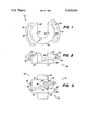
- FIG. 1 is a top view of a cam member according to the present invention
- FIG. 2 is a side view of the cam member of FIG. 1;
- FIG. 3 is a side view of a pair of the cam members of the present invention mated together.
- the stroke limiting collar 10 is comprised of a pair of identical cam members 11a and 11b which mate together, as shown in FIG. 3.
- the cam member 11a includes a generally cylindrical body 12.
- the upper portion of the body 11 (viewing FIG. 2) is formed into a pair of ramp members 14 and 16 which extend radially outwardly from the body 12.
- the ramp members 14 and 16 form a pair of inclined axially and radially extending ramp surfaces 18 and 20, respectively.
- the ramps include arcuately extending slots 22 and 24 which have inner edges which are spaced radially outwardly from the outer peripheral surface 26 of the body 12 in order to provide clearance for attaching bolts 27, as shown in FIG. 3.
- a cylinder rod-receiving aperature or slot 28 extends into the central portion of the body 12.
- the slot 28 permits the cam member 10 to be slid on and off the rod of a hydraulic cylinder without disconnecting the rod from the apparatus to which it is connected.
- the size of the slot 28 can be varied to accommodate different rod sizes.
- the collar 10 is formed by sliding a pair of cam members 11a and 11b onto the rod 30 of a cylinder, each with its ramp members 14 engaging the ramp member 16 of the other cam member.
- the cam members may be rotated with respect to each other until the coupled pair has the desired thickness between the oppositely facing ends 32 of the bodies 12. Then, the two cam members are bolted rigidly together by means such as bolts or cap screws 27.
Abstract
A cylinder stop or collar includes a pair of identical mating cam members. Each cam member has a body and a pair of ramps which define cam surfaces. The ramps have slots for receiving attaching means such as bolts. Each cam member also has a slot so that it may be slid on and off the rod of a cylinder without disconnecting the cylinder.
Description
The present invention relates to a mechanical stroke limiting collar for a hydraulic cylinder.
Mechanical stops or collars are needed to control or limit the stroke of hydraulic cylinders in a number of applications. Such stops are used on the cylinders of agricultural implements such as planters and discs, etc., to control or limit the operating depths of the implement. Spacing washers (such as shown in U.S. Pat. No. 4,073,345) and stroke control segments (such as manufactured by Pederson-Sells Equipment Co., Inc.) are available. However, the fine adjustment of such devices is limited to the width of the thinnest washer or segment. Threaded stop systems, such as described in U.S. Pat. No. 3,905,279, are subject to seizure due to rusty or dirty threads. Other stop or collar systems may require partial disassembly of the cylinder to permit installation or removal of the stops or collars.
An object of the present invention is to provide a steplessly adjustable stroke-limiting collar.
Another object of the present invention is to provide such a collar which can be easily installed and removed without disconnecting the cylinder from the apparatus it operates.
These and other objects are achieved by the present invention which provides a locking collar comprised of a pair of identical mating cam members. Each cam member has a body and a pair of ramps which define cam surfaces. The ramps have slots for receiving attaching means such as bolts. The two ramp members can be rotated with respect to each other to achieve a stepless thickness adjustment. Each cam member also has a rod-receiving opening so that it may be slid on and off the rod of a cylinder without disconnecting the cylinder.
FIG. 1 is a top view of a cam member according to the present invention;
FIG. 2 is a side view of the cam member of FIG. 1; and
FIG. 3 is a side view of a pair of the cam members of the present invention mated together.
The stroke limiting collar 10 is comprised of a pair of identical cam members 11a and 11b which mate together, as shown in FIG. 3.
Referring now to FIGS. 1 and 2, the cam member 11a includes a generally cylindrical body 12. The upper portion of the body 11 (viewing FIG. 2) is formed into a pair of ramp members 14 and 16 which extend radially outwardly from the body 12. The ramp members 14 and 16 form a pair of inclined axially and radially extending ramp surfaces 18 and 20, respectively. The ramps include arcuately extending slots 22 and 24 which have inner edges which are spaced radially outwardly from the outer peripheral surface 26 of the body 12 in order to provide clearance for attaching bolts 27, as shown in FIG. 3.
A cylinder rod-receiving aperature or slot 28 extends into the central portion of the body 12. The slot 28 permits the cam member 10 to be slid on and off the rod of a hydraulic cylinder without disconnecting the rod from the apparatus to which it is connected. The size of the slot 28 can be varied to accommodate different rod sizes.
As shown in FIG. 3, the collar 10 is formed by sliding a pair of cam members 11a and 11b onto the rod 30 of a cylinder, each with its ramp members 14 engaging the ramp member 16 of the other cam member. The cam members may be rotated with respect to each other until the coupled pair has the desired thickness between the oppositely facing ends 32 of the bodies 12. Then, the two cam members are bolted rigidly together by means such as bolts or cap screws 27.
While the invention has been described in conjunction with a specific embodiment, it is to be understood that many alternatives, modifications and variations will be apparent to those skilled in the art in light of the aforegoing description. Accordingly, this invention is intended to embrace all such alternatives, modifications and variations which fall within the spirit and scope of the appended claims.
Claims (1)
1. A cylinder stroke limiting collar comprising:
(a) a pair of complimentary mating cam members, each cam member comprising:
(1) a cylindrical body having a rod-receiving opening extending therein from a central portion of the body out to an outer peripheral surface thereof; and
(2) a pair of curved ramps extending radially outwardly from the body, said ramps being inclined with respect to an axis of the body, each ramp defining a generally axially facing and inclined cam surface for engagement with a complimentary cam surface of the mating cam member, axial thickness adjustment of the collar being produced by relative rotation of the complimentary cam surfaces, and each ramp having an arcuately extending fastener-receiving slot therein, said slot having a radially inner edge spaced radially outwardly from the outer peripheral surface of the body; and
(b) fastening means extending through the slots for fastening the mating cam members together.
Priority Applications (13)
| Application Number | Priority Date | Filing Date | Title |
|---|---|---|---|
| US06/504,004 US4469014A (en) | 1983-06-13 | 1983-06-13 | Cylinder spacer |
| CA000454470A CA1206395A (en) | 1983-06-13 | 1984-05-16 | Cylinder spacer |
| DE8484105915T DE3463825D1 (en) | 1983-06-13 | 1984-05-24 | Stroke-limiting collar for a piston and cylinder |
| AT84105915T ATE27342T1 (en) | 1983-06-13 | 1984-05-24 | STROKE LIMITING RING FOR A PISTON AND CYLINDER. |
| EP84105915A EP0129096B1 (en) | 1983-06-13 | 1984-05-24 | Stroke-limiting collar for a piston and cylinder |
| BR8402633A BR8402633A (en) | 1983-06-13 | 1984-05-31 | CYLINDER COURSE LIMITER NECKLACE |
| AU28994/84A AU546716B2 (en) | 1983-06-13 | 1984-06-04 | Cylinder stroke-limiting collar |
| DK288284A DK288284A (en) | 1983-06-13 | 1984-06-12 | Stroke-length limiting requirement for a stamped cylinder |
| AR296899A AR232032A1 (en) | 1983-06-13 | 1984-06-12 | A CYLINDER STROKE LIMITING NECKLACE |
| IE1470/84A IE55826B1 (en) | 1983-06-13 | 1984-06-12 | Stroke-limiting collar for a piston and cylinder |
| ZA844422A ZA844422B (en) | 1983-06-13 | 1984-06-12 | Cylinder spacer |
| ES1984289478U ES289478Y (en) | 1983-06-13 | 1984-06-12 | A LIMITING TRAVEL NECKLACE INTENDED FOR THE MOUNTING ON THE ROD OF A PLUNGER AND CYLINDER UNIT. |
| JP59121661A JPS6011707A (en) | 1983-06-13 | 1984-06-13 | Limit collar of cylinder stroke |
Applications Claiming Priority (1)
| Application Number | Priority Date | Filing Date | Title |
|---|---|---|---|
| US06/504,004 US4469014A (en) | 1983-06-13 | 1983-06-13 | Cylinder spacer |
Publications (1)
| Publication Number | Publication Date |
|---|---|
| US4469014A true US4469014A (en) | 1984-09-04 |
Family
ID=24004464
Family Applications (1)
| Application Number | Title | Priority Date | Filing Date |
|---|---|---|---|
| US06/504,004 Expired - Lifetime US4469014A (en) | 1983-06-13 | 1983-06-13 | Cylinder spacer |
Country Status (13)
| Country | Link |
|---|---|
| US (1) | US4469014A (en) |
| EP (1) | EP0129096B1 (en) |
| JP (1) | JPS6011707A (en) |
| AR (1) | AR232032A1 (en) |
| AT (1) | ATE27342T1 (en) |
| AU (1) | AU546716B2 (en) |
| BR (1) | BR8402633A (en) |
| CA (1) | CA1206395A (en) |
| DE (1) | DE3463825D1 (en) |
| DK (1) | DK288284A (en) |
| ES (1) | ES289478Y (en) |
| IE (1) | IE55826B1 (en) |
| ZA (1) | ZA844422B (en) |
Cited By (9)
| Publication number | Priority date | Publication date | Assignee | Title |
|---|---|---|---|---|
| US4747723A (en) * | 1987-02-06 | 1988-05-31 | Hasley George E | Universal joint coupling |
| US4821624A (en) * | 1988-02-29 | 1989-04-18 | Deere & Company | Stroke limiter for hydraulic cylinder |
| US5014598A (en) * | 1988-12-30 | 1991-05-14 | Neles-Jamesbury Corporation | Fluid pressure actuator |
| US5988293A (en) * | 1998-05-12 | 1999-11-23 | Deere & Company | Gauge structure for a cylinder operated depth control |
| US20070287228A1 (en) * | 2004-12-09 | 2007-12-13 | Infineon Technologies Ag | Semiconductor Package and Method of Assembling the Same |
| WO2013037341A1 (en) * | 2011-09-16 | 2013-03-21 | Schaeffler Technologies AG & Co. KG | Stop arrangement for the retracted piston rod of a master cylinder |
| US10167888B2 (en) * | 2016-12-29 | 2019-01-01 | Shon E. Barker | Multi-orientable strut channel support system |
| US10543817B2 (en) * | 2016-12-15 | 2020-01-28 | Schwing America, Inc. | Powered rear outrigger systems |
| US20220213933A1 (en) * | 2019-05-29 | 2022-07-07 | Mitsubishi Heavy Industries Engine & Turbocharger, Ltd. | Coupling device and rotational phase adjustment method for coupling device |
Citations (9)
| Publication number | Priority date | Publication date | Assignee | Title |
|---|---|---|---|---|
| US1496485A (en) * | 1922-07-25 | 1924-06-03 | Neal Newton Mccain | Picker cam |
| US1584310A (en) * | 1925-11-16 | 1926-05-11 | Draper Corp | Cam for looms |
| US2763481A (en) * | 1952-04-17 | 1956-09-18 | Harry H Hackett | Pneumatic feed attachment for tape dispensers |
| US3858987A (en) * | 1974-05-21 | 1975-01-07 | Siemens Ag | Drive shaft flange coupling structure having a fixed shear speed |
| US3905279A (en) * | 1973-09-13 | 1975-09-16 | United Hydraulics Corp | Piston and cylinder assembly with external mechanical lock |
| US3921504A (en) * | 1973-09-27 | 1975-11-25 | Owens Illinois Inc | Adjustable stroke invert drive motor for a glass forming machine |
| US3958493A (en) * | 1973-08-20 | 1976-05-25 | Tokico Ltd. | Multiple-stage actuating device |
| US4073345A (en) * | 1977-02-14 | 1978-02-14 | Miller Maurice E | Disc harrow wheel lock-down with depth control adjustment structure |
| US4155433A (en) * | 1977-10-04 | 1979-05-22 | P. L. Porter Company | Stroke-limiting stop for positioning device |
Family Cites Families (3)
| Publication number | Priority date | Publication date | Assignee | Title |
|---|---|---|---|---|
| DE1247138B (en) * | 1963-03-12 | 1967-08-10 | Ingbuero Gebrueder Holtschmidt | Hydraulic drive with adjustable stroke |
| DE2340555A1 (en) * | 1973-08-10 | 1975-02-27 | Schleicher Kg Hermann | DEVICE FOR PERIODIC LATERAL MOVEMENT OF BAR- OR STRIP-SHAPED WORKPIECES |
| DE2651398A1 (en) * | 1976-11-11 | 1978-05-18 | Willi Horcher | Servo or actuating element for reciprocating component - has piston and cylinder actuator with externally adjustable travel limiting stops |
-
1983
- 1983-06-13 US US06/504,004 patent/US4469014A/en not_active Expired - Lifetime
-
1984
- 1984-05-16 CA CA000454470A patent/CA1206395A/en not_active Expired
- 1984-05-24 AT AT84105915T patent/ATE27342T1/en not_active IP Right Cessation
- 1984-05-24 EP EP84105915A patent/EP0129096B1/en not_active Expired
- 1984-05-24 DE DE8484105915T patent/DE3463825D1/en not_active Expired
- 1984-05-31 BR BR8402633A patent/BR8402633A/en unknown
- 1984-06-04 AU AU28994/84A patent/AU546716B2/en not_active Ceased
- 1984-06-12 ZA ZA844422A patent/ZA844422B/en unknown
- 1984-06-12 ES ES1984289478U patent/ES289478Y/en not_active Expired
- 1984-06-12 DK DK288284A patent/DK288284A/en unknown
- 1984-06-12 AR AR296899A patent/AR232032A1/en active
- 1984-06-12 IE IE1470/84A patent/IE55826B1/en unknown
- 1984-06-13 JP JP59121661A patent/JPS6011707A/en active Pending
Patent Citations (9)
| Publication number | Priority date | Publication date | Assignee | Title |
|---|---|---|---|---|
| US1496485A (en) * | 1922-07-25 | 1924-06-03 | Neal Newton Mccain | Picker cam |
| US1584310A (en) * | 1925-11-16 | 1926-05-11 | Draper Corp | Cam for looms |
| US2763481A (en) * | 1952-04-17 | 1956-09-18 | Harry H Hackett | Pneumatic feed attachment for tape dispensers |
| US3958493A (en) * | 1973-08-20 | 1976-05-25 | Tokico Ltd. | Multiple-stage actuating device |
| US3905279A (en) * | 1973-09-13 | 1975-09-16 | United Hydraulics Corp | Piston and cylinder assembly with external mechanical lock |
| US3921504A (en) * | 1973-09-27 | 1975-11-25 | Owens Illinois Inc | Adjustable stroke invert drive motor for a glass forming machine |
| US3858987A (en) * | 1974-05-21 | 1975-01-07 | Siemens Ag | Drive shaft flange coupling structure having a fixed shear speed |
| US4073345A (en) * | 1977-02-14 | 1978-02-14 | Miller Maurice E | Disc harrow wheel lock-down with depth control adjustment structure |
| US4155433A (en) * | 1977-10-04 | 1979-05-22 | P. L. Porter Company | Stroke-limiting stop for positioning device |
Non-Patent Citations (2)
| Title |
|---|
| Pederson-Sells Equipment Co., Inc., "Strike Control Segments", 1979, p. 140 (1979). |
| Pedevson Sells Equipment Co., Inc., Strike Control Segments , 1979, p. 140 (1979). * |
Cited By (14)
| Publication number | Priority date | Publication date | Assignee | Title |
|---|---|---|---|---|
| US4747723A (en) * | 1987-02-06 | 1988-05-31 | Hasley George E | Universal joint coupling |
| US4821624A (en) * | 1988-02-29 | 1989-04-18 | Deere & Company | Stroke limiter for hydraulic cylinder |
| US5014598A (en) * | 1988-12-30 | 1991-05-14 | Neles-Jamesbury Corporation | Fluid pressure actuator |
| US5988293A (en) * | 1998-05-12 | 1999-11-23 | Deere & Company | Gauge structure for a cylinder operated depth control |
| US20070287228A1 (en) * | 2004-12-09 | 2007-12-13 | Infineon Technologies Ag | Semiconductor Package and Method of Assembling the Same |
| US7851261B2 (en) | 2004-12-09 | 2010-12-14 | Infineon Technologies Ag | Semiconductor package and method of assembling the same |
| WO2013037341A1 (en) * | 2011-09-16 | 2013-03-21 | Schaeffler Technologies AG & Co. KG | Stop arrangement for the retracted piston rod of a master cylinder |
| US10543817B2 (en) * | 2016-12-15 | 2020-01-28 | Schwing America, Inc. | Powered rear outrigger systems |
| US10167888B2 (en) * | 2016-12-29 | 2019-01-01 | Shon E. Barker | Multi-orientable strut channel support system |
| US10302113B2 (en) * | 2016-12-29 | 2019-05-28 | Shon E. Barker | Multi-orientable strut channel support system |
| US20190257337A1 (en) * | 2016-12-29 | 2019-08-22 | Shon E. Barker | Multi-Orientable Strut Channel Support System |
| US10508671B2 (en) * | 2016-12-29 | 2019-12-17 | Shon E. Barker | Multi-Orientable strut channel support system |
| US20220213933A1 (en) * | 2019-05-29 | 2022-07-07 | Mitsubishi Heavy Industries Engine & Turbocharger, Ltd. | Coupling device and rotational phase adjustment method for coupling device |
| US11906003B2 (en) * | 2019-05-29 | 2024-02-20 | Mitsubishi Heavy Industries Engine & Turbocharger, Ltd. | Coupling device and rotational phase adjustment method for coupling device |
Also Published As
| Publication number | Publication date |
|---|---|
| ES289478Y (en) | 1986-10-01 |
| EP0129096A2 (en) | 1984-12-27 |
| ATE27342T1 (en) | 1987-06-15 |
| JPS6011707A (en) | 1985-01-22 |
| ES289478U (en) | 1986-02-16 |
| CA1206395A (en) | 1986-06-24 |
| AU546716B2 (en) | 1985-09-12 |
| IE841470L (en) | 1984-12-13 |
| IE55826B1 (en) | 1991-01-30 |
| DK288284A (en) | 1984-12-14 |
| EP0129096B1 (en) | 1987-05-20 |
| DE3463825D1 (en) | 1987-06-25 |
| BR8402633A (en) | 1985-04-30 |
| AU2899484A (en) | 1984-12-20 |
| AR232032A1 (en) | 1985-04-30 |
| ZA844422B (en) | 1986-01-29 |
| DK288284D0 (en) | 1984-06-12 |
| EP0129096A3 (en) | 1985-11-27 |
Similar Documents
| Publication | Publication Date | Title |
|---|---|---|
| US5674034A (en) | Locking nut assembly | |
| US4469014A (en) | Cylinder spacer | |
| EP2649689B1 (en) | Apparatus for fixing a cable to a cable outlet stub | |
| US4637502A (en) | Overload release mechanism for torque couplings | |
| DE1650114B2 (en) | Coupling for connecting a pipe to a connector | |
| EP0125452A1 (en) | Arrangement for securing a roller ring on a cantilever-supported roller shaft | |
| DE4243561C2 (en) | Gland packing | |
| DE8209420U1 (en) | PISTON FOR CONTACTLESS PISTON POSITION SENSING | |
| WO1991015700A1 (en) | Device for holding cables, pipes, hoses or the like | |
| EP0132567B1 (en) | Clamping device for a ring wheel | |
| GB2087514A (en) | A coupling device | |
| DE2647250C3 (en) | Screwed piston for internal combustion engines | |
| EP1288611B1 (en) | Angle measurement system | |
| GB2053339A (en) | A support and clamping ring | |
| EP0731284B1 (en) | Clamp for cylindric elements | |
| DE2406151A1 (en) | DEVICE FOR TURNOOTING A PART TO A SHAFT | |
| US6032569A (en) | Locking device for securing a piston to a piston rod | |
| DE3702867A1 (en) | DEVICE FOR ELASTICALLY CONNECTING SHAFTS | |
| US3043151A (en) | Variable pitch sheave | |
| EP0246416B1 (en) | Device for rigidly connecting a component part on a shaft | |
| DE717866C (en) | Seat fastening of the roller bearing race rings | |
| DE2522829A1 (en) | DISTRIBUTOR FOR COMBUSTION MACHINERY | |
| DE4041683A1 (en) | Hydraulic nut for clamping cutter on mandrel - has piston pressing on inside of flexible ring forming abutment face of nut | |
| DE3744284A1 (en) | Coupling device for the releasable connection of two parts to one another | |
| DE4201394C2 (en) | Hydraulic tensioning element |
Legal Events
| Date | Code | Title | Description |
|---|---|---|---|
| AS | Assignment |
Owner name: DEERE & COMPANY MOLINE, IL A CORP. OF DE Free format text: ASSIGNMENT OF ASSIGNORS INTEREST.;ASSIGNOR:NELSON, ROGER J.;REEL/FRAME:004141/0042 Effective date: 19830526 |
|
| STCF | Information on status: patent grant |
Free format text: PATENTED CASE |
|
| FPAY | Fee payment |
Year of fee payment: 4 |
|
| FEPP | Fee payment procedure |
Free format text: PAYOR NUMBER ASSIGNED (ORIGINAL EVENT CODE: ASPN); ENTITY STATUS OF PATENT OWNER: LARGE ENTITY |
|
| FPAY | Fee payment |
Year of fee payment: 8 |
|
| FPAY | Fee payment |
Year of fee payment: 12 |