US4467271A - Test apparatus for determination of vibration characteristics of piezoelectric transducers - Google Patents
Test apparatus for determination of vibration characteristics of piezoelectric transducers Download PDFInfo
- Publication number
- US4467271A US4467271A US06/340,882 US34088282A US4467271A US 4467271 A US4467271 A US 4467271A US 34088282 A US34088282 A US 34088282A US 4467271 A US4467271 A US 4467271A
- Authority
- US
- United States
- Prior art keywords
- signal
- transducer
- piezoelectric transducer
- test apparatus
- excitation signal
- Prior art date
- Legal status (The legal status is an assumption and is not a legal conclusion. Google has not performed a legal analysis and makes no representation as to the accuracy of the status listed.)
- Expired - Fee Related
Links
- 238000012360 testing method Methods 0.000 title claims description 33
- 230000005284 excitation Effects 0.000 claims abstract description 36
- 238000005259 measurement Methods 0.000 claims abstract description 33
- 230000004044 response Effects 0.000 claims abstract description 29
- 230000000694 effects Effects 0.000 claims abstract description 8
- 238000011156 evaluation Methods 0.000 claims abstract description 7
- 230000007613 environmental effect Effects 0.000 claims description 6
- 238000012545 processing Methods 0.000 claims description 4
- 238000000034 method Methods 0.000 abstract description 13
- 230000008569 process Effects 0.000 abstract description 2
- 230000006399 behavior Effects 0.000 description 5
- 239000012528 membrane Substances 0.000 description 4
- 230000035939 shock Effects 0.000 description 4
- 239000003990 capacitor Substances 0.000 description 3
- 230000006870 function Effects 0.000 description 3
- 230000010355 oscillation Effects 0.000 description 3
- 230000001629 suppression Effects 0.000 description 3
- 230000001360 synchronised effect Effects 0.000 description 3
- 230000002411 adverse Effects 0.000 description 2
- 230000008901 benefit Effects 0.000 description 2
- 230000005520 electrodynamics Effects 0.000 description 2
- 230000035945 sensitivity Effects 0.000 description 2
- 239000013598 vector Substances 0.000 description 2
- 230000001133 acceleration Effects 0.000 description 1
- 230000008859 change Effects 0.000 description 1
- 230000005669 field effect Effects 0.000 description 1
- 230000010358 mechanical oscillation Effects 0.000 description 1
- 239000008188 pellet Substances 0.000 description 1
- 230000000737 periodic effect Effects 0.000 description 1
- 230000010363 phase shift Effects 0.000 description 1
- 238000002360 preparation method Methods 0.000 description 1
- 238000003672 processing method Methods 0.000 description 1
- 238000010998 test method Methods 0.000 description 1
- 230000009466 transformation Effects 0.000 description 1
- 230000001960 triggered effect Effects 0.000 description 1
Images

Classifications
-
- G—PHYSICS
- G01—MEASURING; TESTING
- G01R—MEASURING ELECTRIC VARIABLES; MEASURING MAGNETIC VARIABLES
- G01R29/00—Arrangements for measuring or indicating electric quantities not covered by groups G01R19/00 - G01R27/00
- G01R29/22—Measuring piezoelectric properties
Definitions
- the present invention relates to a measuring set-up for the determination of the vibration characteristics of transducers or transducer systems with piezoelectric measuring elements, comprising an AC generator which may be connected to the signal leads of the transducer to be tested in order to induce mechanical vibrations of the measuring element due to the inverse piezoelectric effect, and a measuring system for the measurement and evaluation of these vibrations.
- the vibration characteristics of piezoelectric transducers which are commonly used to transform mechanical changes of state, e.g. pressure changes, accelerations etc. into electrical signals, can be determined by various known methods and testing arrangements.
- mechanical shock excitation of the measuring elements resulting from the impact of a pellet is used to induce slightly damped vibrations in the measuring elements, which are evaluated by means of a storage oscilloscope connected to the signal leads of the transducer to be tested.
- This known method suffers from the disadvantage that the mechanical shock will only induce a damped oscillation in one characteristic frequency of the measuring element, which will not permit a comprehensive appraisal of the vibration behaviour of the transducer.
- piezoelectric pressure transducers whose sensitive elements are directly linked with a membrane exposed to the pressure to be measured, this membrane itself will usually be taken as one of the electrodes of the evaluation capacitor.
- a similar arrangement is based on the fact that vibrations in the piezoelectric measuring elements of the transducers are directly excited by electrostatic attraction due to a voltage applied between an external electrode and the transducer membrane. Since these electrostatic attraction forces are extremely small, the resulting piezoelectric signals to be evaluated tend to be very small as well, thus making the method applicable to transducers with a high force or pressure sensitivity only.
- the transducers to be measured must be firmly held in a very stable frame in order to effectuate parallel adjustment of the external electrode with the required precision.
- the transducer or its membrane must furthermore be polished most carefully to permit the application of the necessary high AC or DC voltage.
- a common disadvantage of all the arrangements mentioned thus far lies in the fact that the vibration characteristics of the transducer cannot be measured with the transducer being mounted in its usual operational position. This makes it impossible to take into account the effects of environmental influences upon the transducer, which to a varying degree are part of every measurement task. Such environmental influences may e.g. arise from the fact that the transducer or rather its housing is fitted into a test bore in the wall of a pressure chamber and is therefore subject to mechanical or thermic stresses, which in adverse cases may directly act e.g. on the bias of the measuring elements themselves or on other variables which have a bearing on the vibrational behaviour of the transducer.
- This aim is attained by providing the measurement system with a subtraction unit whose one input is fed with the excitation signal of the AC generator while the other input is connected to the signal leads of the transducer, and by further providing an evaluation unit, which is connected to the output of the subtraction unit and will display and process the measurement signal derived as the difference of the response signal of the transducer and a signal proportional to the excitation signal.
- the mechanical oscillations of the measuring element excited by the AC generator connected to the ordinary signal leads of the transudcer will in turn produce a response signal via the normal piezoelectric effect, which will be mixed with the excitation signal.
- the subtraction unit may be used to subtract that part of the mix stemming from the excitation signal, thus making available the measurement signal describing the vibrational characteristics of the transducer tested, which has the same frequency as the excitation signal supplied by the AC generator.
- the following evaluation unit may be used to transform by standard rectifying techniques the measurement signal into an amplitude-proportional DC signal, and, possibly, to determine the phase of the measurement signal relative to the excitation signal by means of a phase-measuring circuit. These values, which determine the measurement signal in a unique manner, may then be displayed in an analog or digital manner and may be recorded or stored in a storage device for further processing.
- a test apparatus will thus make it possible to study the vibrational behavior of a transducer fitted into a test bore of the wall of a pressure chamber e.g., by simply connecting the signal leads of the transducer to the measuring system. This will permit registering any influence of the normal operating environment on the function and especially on the vibration characteristics of the transducer, thus making tests particularly practice-oriented.
- An enhanced version of this invention provides the measuring system with its own impedance chain, with the connected transducer forming part of this chain and the response signal of the transducer being derived from the other part or one of the other parts of the impedance chain.
- the phase-shifting components of the measuring system i.e. the cable capacitances, input capacitances of the subtraction unit, stray capacitances in the transducer and the capacitance of the measuring element itself may be compensated by means of the impedance chain.
- the impedance chain it will be particularly advantageous for the impedance chain to contain an adjustable element for taking into account the differing characteristics of various transducers or transudcer systems.
- a further proposal of the present invention suggests placing the transducer to be measured in the grounded part of the unilaterally grounded impedance network which consists either of phase-shifting elements only or of a combination of phase-shifting and purely resistive elements. It permits the transducer to be measured to be connected to any grounded measuring set-up without further preparations. This is of particular advantage for piezoelectric transducers with only one signal lead (charge pick-up lead), where the other electrode of the measuring element is connected to the transducer housing.
- a test apparatus is configured according to the present invention in such a way as to place the transducer in the voltage source side, e.g., between voltage source and mid-point, of the unilaterally grounded voltage divider circuit, thus forming a so-called admittance network, where the cable capacitances will present a capacitive reactance against ground and may be taken as part of the impedance between mid-point and ground, leaving ony capacitances and interior resistances of the transducer to be explicitly dealt with. Since the cable capacitances of short cables have the same order of magnitude as the capacitance of the measuring element, the interior resistance and the input capacitance against ground of the subtraction unit will essentially determine the measurement sensitivity.
- Transducers with one signal lead only may alo be measured by means of an admittance network as described above.
- the excitation signal of the AC generator is applied to the transducer housing, while the response signal is taken from the signal lead; a compensation resistor must be provided.
- a further improved variant of the present invention will incorporate into the subtraction unit a differential amplifier or an operational amplifier with a differentiating input.
- the output of this amplifier will directly represent the electric reaction of the piezoelectric element as an AC signal of the same frequency as the excitation signal, provided that the excitation signal has been separated properly from the response signal, which will depend on the common-mode suppression characteristics of the amplifier.
- a further enhancement of this invention envisages yet another adjustable voltage divider circuit connected to the subtraction unit and supplying a subtraction voltage which may be used to compensate the electric reaction of the excitation signal due to the parallel resistances of the transducer or the connecting cable.
- the measurement signal proper i.e. the electric reaction of the transducer is extracted from the response signal in such a way that those components of the excitation signal arising from parallel resistances in the transducer or in the connecting cable are subtracted from the response signal.
- These parallel resistances may be measured at frequencies of the excitation signal, which do not correspond to any resonances of the transducer or the whole transducer system, and the excitation signal component of the response signal may be calculated from this.
- Precision compensation of these parallel resistances may also be achieved by adjusting the phase angle of the response signal to zero or to small negative values, or by adjusting the additional voltage divider circuit using the symmetry of a resonance curve of the response signal. If the additional voltage divider circuit is not precisely adjusted the phase of the measurement signal may be evaluated as a measurement variable.
- a further enhanced variation of the present invention suggests that the additional voltage divider circuit supplying the subtraction voltage be roughly adjustable to a series of identical transducers, that both the excitation signal and the response signal be digitized by means of an analog/digital converter, and that precise compensation of the reaction of the excitation signal be carried out by digital signal processing.
- the--at least partial--use of an analog subtraction technique for eliminating the excitation signal will permit a rough adjustment of the measurement system to a range of transducers, which will reduce the resolution requirements placed on the AD-converter used for precision adjustment. This precision adjustment may then be performed by digital signal processing methods.
- the subtraction unit may be configured as a bridge circuit.
- the transducer to be tested and another identical transducer are each placed in a branch of the bridge network such that the electrical reaction of the excitation signal is compensated.
- This method will permit varying of the environmental conditions of the transducer to be tested in order to simulate various operational conditions.
- the vibration characteristics of the transducer as functions of changing external influences, e.g. pressure, temperature may thus be determined in a simple manner. Since the environmental conditions for the second, identical transducer in the bridge network are being kept constant, the measurement signal obtained will portray the changes in vibrational behaviour with environmental changes of the transducer to be tested in a significant manner.
- a further enhancement of this invention suggests the use of the charge amplifier which is normally used during ordinary operation of the transducer, as part of the subtraction unit of the test apparatus.
- an essential component of the operational measurement system will simultaneously be utilized as part of the test set-up for the transducer, which will reduce the cost of the testing system on the one hand, while greatly simplifying periodic testing of the vibration characteristics of the transducer during normal operation on the other hand.
- a changeover switch contained in the test set-up may be used to change the function of the amplifier and thus to alternate between normal operation and test mode.
- the present invention also envisages the use of a micro-processor or micro-computer in the measurement system in order to control the test procedure and/or for signal processing purposes, thereby simplifying the entire procedure.
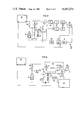
- FIG. 1 shows a variant of the present invention, incorporating a transducer with two signal leads, in the form of an admittance network;
- FIG. 2 shows a variant of the set-up for a transducer with one signal lead in the form of an impedance network
- FIG. 3 shows another variant of the present invention in the form of a bridge circuit
- FIG. 4 shows another variant of this invention with a synchronous rectifier
- FIG. 5 shows another variant of the invention with a charge amplifier.
- the test set-up of FIG. 1 shows a transducer to be measured with two signal leads 1 and 2, the piezoelectric measuring element 3 being insulated against the transducer housing 4.
- This apparatus comprises a frequency-variable sinewave generator 5 with low non-linear distortion, a phase-variable impedance 6 and a differential amplifier 7 with high-resistance inputs and excellent common-mode suppression.
- the output of the differential amplifier 7 is connected to an AC voltmeter 8 displaying the measurement signal.
- the resistor 9 compensates the input current and, together with the input resistance of the non-inverting input of the differential amplifier and the piezoelectric element, forms a voltage divider circuit from which the response signal of the piezoelectric sensor is derived.
- the subtraction unit 10 compensates the excitation signal component of the response signal, the variable impedance 6 being adjusted so as to supply the value of the excitation signal to be subtracted, and the differential amplifier 7 performing the subtraction.
- the subtraction unit as such is indicated by a broken line and is designated 10.
- FIG. 2 shows a test apparatus for a transducer with one signal lead 11 only, the other electrode of the piezoelectric measuring element 13 being connected to the housing 14 of the transducer.
- the response signal of the transducer is taken from point 12, where the resistor 19 is connected to the transducer.
- the differential amplifier 17 By means of the differential amplifier 17 a fraction of the excitation signal, which can be adjusted via the potentiometer 16, is subtracted from the response signal.
- the measurement signal may be displayed by an AC voltmeter 18 or fed into a recording device 20.
- the subtraction unit again is indicated by a broken line and is designated 10'.
- FIG. 3 shows a test set-up for a two-lead transducer (21, 22) using an admittance circuit.
- An impedance network consisting of the variable impedances 27 and 28 and of impedance 29, and a reference potentiometer 26 are also shown.
- the resistors 27 and 29 compensate ohmic losses in the cables and in the transducer as well as the input impedance of the differential amplifier. They also help to improve the common-mode suppression of the operational amplifier.
- the variable capacitor 28 compensates the cable capacitances and stray-capacitances of the transducer.
- the operational amplifier 30 determines the elctric reaction of the transducer by subtracting a fraction of the excitation signal derived from potentiometer 26 from the response signal of the transducer.
- the excitation signal of the AC generator 25 should be applied to the housing 24 of the transducer, and the signal lead should be connected to parts 27, 28, 29 and to the non-inverting input of the operational amplifier 30.
- the subtraction unit is again indicated by a broken line and designated 10".
- the output of the subtraction unit 10" again is connected to an AC voltmeter 31 for displaying the amplitude of the measurement signal.
- FIG. 4 shows a test arrangement with a controllable AC generator 35 and an impedance network comprising the potentiometer 36 and the variable capacitance diode 33.
- this impedance network By means of this impedance network the phase-shift of the subtraction signal to be subtracted from the response signal of the transducer 32 to be tested, may be adjusted via a micro-processor 42 and an analog/digital converter 43.
- the measurement signal is obtained from the phase-shifting impedance 39, which is connected to the signal lead of the transducer 32.
- the electric reaction of the transducer is directly obtained as an AC signal.
- the multiplier unit 37 performs a phase-preserving rectification of the measurement signal, and the integrating low-pass 38 eliminates the high-frequency multiplication products. Synchronous rectification shifted in phase by 90 degrees will produce the vector part of the phase-shifted signal of the electric reaction. Via a multiplexer 40 and an analog-digital converter 41 the amlitude vectors are fed into the micro-processor 42. They may then be converted into amplitude and phase, and will also be available via the interface 45. If the operational amplifier 44 is used as a charge amplifier at the same time, the measurement values of the transducer may be corrected in the micro-processor 42 by means of a Fourier transformation. The subtraction unit proper again is framed by a broken line and is designated 10"'.
- FIG. 5 shows a set-up in which measurements with the transducer 51 may be alternated with the determination of the vibration characteristics of the transducer.
- the AC generator 55 provides an excitation signal which may be applied to the phase-variable impedance chain 52 by contact 53a of switch 53.
- the response signal of the transducer 51 to be tested is amplified by the operational amplifier 54; another operational amplifier 56 determines the electric reaction of the transducer, i.e. the measurement signal proper, by subtracting a fraction of the excitation signal from the response signal.
- the measurement signal is rectified by a precision rectifier 58 and is displayed on a voltmeter 58'.
- a frequency curve of the transducer may be drawn.
- tipping switch 53 which contains contacts 53a, 53b, 53c, the operational amplifier 54 will turn into a charge amplifier whose output signal may be stored in a CCD memory 59 triggered internally or externally, or may be recorded by the plotter 60.
- the subtraction unit proper is designated 10" " in this case.
Landscapes
- Physics & Mathematics (AREA)
- General Physics & Mathematics (AREA)
- Measurement Of Mechanical Vibrations Or Ultrasonic Waves (AREA)
Applications Claiming Priority (2)
| Application Number | Priority Date | Filing Date | Title |
|---|---|---|---|
| AT0061381A AT369549B (de) | 1981-02-10 | 1981-02-10 | Pruefeinrichtung zur bestimmung von schwingungseigenschaften |
| AT613/81 | 1981-02-10 |
Publications (1)
| Publication Number | Publication Date |
|---|---|
| US4467271A true US4467271A (en) | 1984-08-21 |
Family
ID=3495229
Family Applications (1)
| Application Number | Title | Priority Date | Filing Date |
|---|---|---|---|
| US06/340,882 Expired - Fee Related US4467271A (en) | 1981-02-10 | 1982-01-19 | Test apparatus for determination of vibration characteristics of piezoelectric transducers |
Country Status (4)
| Country | Link |
|---|---|
| US (1) | US4467271A (ja) |
| AT (1) | AT369549B (ja) |
| CH (1) | CH657457A5 (ja) |
| DE (1) | DE3200362C2 (ja) |
Cited By (21)
| Publication number | Priority date | Publication date | Assignee | Title |
|---|---|---|---|---|
| US4578634A (en) * | 1983-05-31 | 1986-03-25 | Westinghouse Electric Corp. | Apparatus for determining frequency versus acceleration characteristics for crystals |
| US4816743A (en) * | 1986-12-19 | 1989-03-28 | Avl Gesellschaft Fur Verbrennungskraftmaschinen Und Messtechnik M.B.H. Prof. Dr.Dr. H.C. Hans List | Method and apparatus for the identification of oscillatory properties as well as for the operation of a piezo-electric tranducer |
| US5262730A (en) * | 1988-04-29 | 1993-11-16 | British Technology Group Ltd. | Apparatus and method for determining the permittivity of samples of material over a wide frequency band |
| ES2111475A1 (es) * | 1995-09-14 | 1998-03-01 | Bardasona Rubio Jose Luis | Aparato e instalacion para medir la piezo-electricidad osea inversa y el correspondiente metodo de medida. |
| US6127829A (en) * | 1997-12-10 | 2000-10-03 | Texas Instruments Incorporated | Method and apparatus for the efficient test of the center frequency of bandpass filters |
| US6154037A (en) * | 1998-10-13 | 2000-11-28 | Globespan Semiconductor, Inc. | System and method for testing distortion in transformers |
| WO2003019205A1 (en) * | 2001-08-27 | 2003-03-06 | Rosemount Inc. | Diagnostics for piezoelectric sensor |
| EP1480023A1 (de) * | 2003-05-20 | 2004-11-24 | Endress + Hauser GmbH + Co. KG | Messgerät mit Vorrichtung zur Erkennung des angeschlossenenen Ultraschallsensors |
| US20050011277A1 (en) * | 2003-06-10 | 2005-01-20 | Gao Robert X. | System and method for load sensing using piezoelectric effect |
| WO2005045783A1 (de) * | 2003-11-04 | 2005-05-19 | Siemens Aktiengesellschaft | Verfahren zur identifikation von analogen messsignalgebern und zugehörige anordnung |
| US20060038858A1 (en) * | 2004-08-18 | 2006-02-23 | Fuji Xerox Co., Ltd. | Inkjet recording apparatus |
| US20060229785A1 (en) * | 2003-12-10 | 2006-10-12 | Bayerische Motoren Werke Aktiengesellschaft | Method for operating a sensor in a safety system |
| US20110316566A1 (en) * | 2009-03-11 | 2011-12-29 | Renishaw Plc | Apparatus and method for digitising impedance |
| US8209151B2 (en) | 2008-07-10 | 2012-06-26 | Avl List Gmbh | Test assembly and procedure for capturing performance data |
| EP2703825A1 (en) * | 2012-08-31 | 2014-03-05 | Meggitt SA | Force sensor and method for testing its reliability |
| RU2524743C2 (ru) * | 2012-11-06 | 2014-08-10 | Закрытое акционерное общество "Вибро-прибор" | Способ бездемонтажной поверки пьезоэлектрического вибропреобразователя на месте эксплуатации |
| RU2538034C2 (ru) * | 2013-02-25 | 2015-01-10 | Федеральное Государственное Унитарное Предприятие "Всероссийский Научно-Исследовательский Институт Физико-Технических И Радиотехнических Измерений" (Фгуп "Вниифтри") | Бездемонтажный способ поверки виброакустических приемников |
| CN112557776A (zh) * | 2020-12-06 | 2021-03-26 | 复旦大学 | 一种压电材料动态压电性能测试系统及方法 |
| CN112752961A (zh) * | 2018-09-25 | 2021-05-04 | 罗伯特·博世有限公司 | 用于求取压电传感器的至少一个传感器特性的方法 |
| US11307326B2 (en) * | 2017-05-03 | 2022-04-19 | Pgs Geophysical As | Calibration of combined acceleration and pressure sensors |
| US11474081B2 (en) * | 2019-03-14 | 2022-10-18 | Kabushiki Kaisha Toshiba | Sensor module |
Families Citing this family (1)
| Publication number | Priority date | Publication date | Assignee | Title |
|---|---|---|---|---|
| DE102016206797A1 (de) | 2015-04-22 | 2016-10-27 | Ifm Electronic Gmbh | Mobile Steuerung für eine mobile Arbeitsmaschine |
Citations (2)
| Publication number | Priority date | Publication date | Assignee | Title |
|---|---|---|---|---|
| US3832630A (en) * | 1972-05-17 | 1974-08-27 | D Etude Const Soc Nat | Method and apparatus of measuring the characteristic resonance frequency of an electric element |
| SU756318A1 (ru) * | 1978-12-12 | 1980-08-15 | Aleksandr V Khramov | Устройство допускового контроля пьезоэлектрических резонаторов 1 |
Family Cites Families (1)
| Publication number | Priority date | Publication date | Assignee | Title |
|---|---|---|---|---|
| DE2822309C2 (de) * | 1978-05-22 | 1983-06-30 | Filial Nr. 2 naučno-issledovatel'skogo instituta pezotechniki, Moskva | Meßeinrichtung zur Bestimmung der Resonanz- und Gegenresonanzfrequenz von Piezoresonatoren |
-
1981
- 1981-02-10 AT AT0061381A patent/AT369549B/de not_active IP Right Cessation
- 1981-12-23 CH CH8265/81A patent/CH657457A5/de not_active IP Right Cessation
-
1982
- 1982-01-08 DE DE3200362A patent/DE3200362C2/de not_active Expired
- 1982-01-19 US US06/340,882 patent/US4467271A/en not_active Expired - Fee Related
Patent Citations (2)
| Publication number | Priority date | Publication date | Assignee | Title |
|---|---|---|---|---|
| US3832630A (en) * | 1972-05-17 | 1974-08-27 | D Etude Const Soc Nat | Method and apparatus of measuring the characteristic resonance frequency of an electric element |
| SU756318A1 (ru) * | 1978-12-12 | 1980-08-15 | Aleksandr V Khramov | Устройство допускового контроля пьезоэлектрических резонаторов 1 |
Cited By (37)
| Publication number | Priority date | Publication date | Assignee | Title |
|---|---|---|---|---|
| US4578634A (en) * | 1983-05-31 | 1986-03-25 | Westinghouse Electric Corp. | Apparatus for determining frequency versus acceleration characteristics for crystals |
| US4816743A (en) * | 1986-12-19 | 1989-03-28 | Avl Gesellschaft Fur Verbrennungskraftmaschinen Und Messtechnik M.B.H. Prof. Dr.Dr. H.C. Hans List | Method and apparatus for the identification of oscillatory properties as well as for the operation of a piezo-electric tranducer |
| US5262730A (en) * | 1988-04-29 | 1993-11-16 | British Technology Group Ltd. | Apparatus and method for determining the permittivity of samples of material over a wide frequency band |
| ES2111475A1 (es) * | 1995-09-14 | 1998-03-01 | Bardasona Rubio Jose Luis | Aparato e instalacion para medir la piezo-electricidad osea inversa y el correspondiente metodo de medida. |
| US6127829A (en) * | 1997-12-10 | 2000-10-03 | Texas Instruments Incorporated | Method and apparatus for the efficient test of the center frequency of bandpass filters |
| US6154037A (en) * | 1998-10-13 | 2000-11-28 | Globespan Semiconductor, Inc. | System and method for testing distortion in transformers |
| WO2003019205A1 (en) * | 2001-08-27 | 2003-03-06 | Rosemount Inc. | Diagnostics for piezoelectric sensor |
| US6531884B1 (en) * | 2001-08-27 | 2003-03-11 | Rosemount Inc. | Diagnostics for piezoelectric sensor |
| EP1480023A1 (de) * | 2003-05-20 | 2004-11-24 | Endress + Hauser GmbH + Co. KG | Messgerät mit Vorrichtung zur Erkennung des angeschlossenenen Ultraschallsensors |
| US20050039533A1 (en) * | 2003-05-20 | 2005-02-24 | Dietmar Spanke | Measuring instrument |
| US7255006B2 (en) | 2003-05-20 | 2007-08-14 | Endress +Hauser Gmbh + Co. Kg | Measuring instrument |
| US20050011277A1 (en) * | 2003-06-10 | 2005-01-20 | Gao Robert X. | System and method for load sensing using piezoelectric effect |
| US7104139B2 (en) * | 2003-06-10 | 2006-09-12 | University Of Massachusetts | System and method for load sensing using piezoelectric effect |
| WO2005045783A1 (de) * | 2003-11-04 | 2005-05-19 | Siemens Aktiengesellschaft | Verfahren zur identifikation von analogen messsignalgebern und zugehörige anordnung |
| US7564251B2 (en) | 2003-11-04 | 2009-07-21 | Siemens Aktiengesellschaft | Method for identifying analog measuring sensors and associated assembly |
| US20070035316A1 (en) * | 2003-11-04 | 2007-02-15 | Jurgen Rupp | Method for identifying analog measuring sensors and associated assembly |
| US20060229785A1 (en) * | 2003-12-10 | 2006-10-12 | Bayerische Motoren Werke Aktiengesellschaft | Method for operating a sensor in a safety system |
| US7539569B2 (en) * | 2003-12-10 | 2009-05-26 | Bayerische Motoren Werke Aktiengesellschaft | Method for operating a sensor in a safety system |
| US20090046121A1 (en) * | 2004-08-18 | 2009-02-19 | Fuji Xerox Co., Ltd. | Inkjet recording apparatus |
| US20060038858A1 (en) * | 2004-08-18 | 2006-02-23 | Fuji Xerox Co., Ltd. | Inkjet recording apparatus |
| US7798596B2 (en) | 2004-08-18 | 2010-09-21 | Fuji Xerox Co., Ltd. | Inkjet recording apparatus |
| US7452049B2 (en) * | 2004-08-18 | 2008-11-18 | Fuji Xerox Co., Ltd. | Inkjet recording apparatus |
| US8209151B2 (en) | 2008-07-10 | 2012-06-26 | Avl List Gmbh | Test assembly and procedure for capturing performance data |
| US20110316566A1 (en) * | 2009-03-11 | 2011-12-29 | Renishaw Plc | Apparatus and method for digitising impedance |
| CN102348957A (zh) * | 2009-03-11 | 2012-02-08 | 瑞尼斯豪公司 | 用于将阻抗数字化的设备和方法 |
| US8890546B2 (en) * | 2009-03-11 | 2014-11-18 | Renishaw Plc | Apparatus and method for digitising impedance |
| US9057655B2 (en) | 2012-08-31 | 2015-06-16 | Meggitt Sa | Force sensor and method for testing its reliability |
| EP2703825A1 (en) * | 2012-08-31 | 2014-03-05 | Meggitt SA | Force sensor and method for testing its reliability |
| CN103674400A (zh) * | 2012-08-31 | 2014-03-26 | 梅吉特股份有限公司 | 力传感器及其可靠性测试方法 |
| RU2524743C2 (ru) * | 2012-11-06 | 2014-08-10 | Закрытое акционерное общество "Вибро-прибор" | Способ бездемонтажной поверки пьезоэлектрического вибропреобразователя на месте эксплуатации |
| RU2538034C2 (ru) * | 2013-02-25 | 2015-01-10 | Федеральное Государственное Унитарное Предприятие "Всероссийский Научно-Исследовательский Институт Физико-Технических И Радиотехнических Измерений" (Фгуп "Вниифтри") | Бездемонтажный способ поверки виброакустических приемников |
| RU2538034C9 (ru) * | 2013-02-25 | 2015-07-20 | Федеральное Государственное Унитарное Предприятие "Всероссийский Научно-Исследовательский Институт Физико-Технических И Радиотехнических Измерений" (Фгуп "Вниифтри") | Бездемонтажный способ поверки виброакустических приемников |
| US11307326B2 (en) * | 2017-05-03 | 2022-04-19 | Pgs Geophysical As | Calibration of combined acceleration and pressure sensors |
| CN112752961A (zh) * | 2018-09-25 | 2021-05-04 | 罗伯特·博世有限公司 | 用于求取压电传感器的至少一个传感器特性的方法 |
| CN112752961B (zh) * | 2018-09-25 | 2023-06-13 | 罗伯特·博世有限公司 | 用于求取压电传感器的至少一个传感器特性的方法 |
| US11474081B2 (en) * | 2019-03-14 | 2022-10-18 | Kabushiki Kaisha Toshiba | Sensor module |
| CN112557776A (zh) * | 2020-12-06 | 2021-03-26 | 复旦大学 | 一种压电材料动态压电性能测试系统及方法 |
Also Published As
| Publication number | Publication date |
|---|---|
| DE3200362C2 (de) | 1984-03-01 |
| CH657457A5 (de) | 1986-08-29 |
| ATA61381A (de) | 1982-05-15 |
| DE3200362A1 (de) | 1982-09-23 |
| AT369549B (de) | 1983-01-10 |
Similar Documents
| Publication | Publication Date | Title |
|---|---|---|
| US4467271A (en) | Test apparatus for determination of vibration characteristics of piezoelectric transducers | |
| US4797620A (en) | High voltage electrostatic surface potential monitoring system using low voltage A.C. feedback | |
| JP3302377B2 (ja) | 静電容量−電圧変換装置及び変換方法 | |
| US3710614A (en) | High precision wide dynamic range viscous loss measuring apparatus | |
| US4675670A (en) | Apparatus for the dynamic and non-contact measurement of small distances | |
| JP4488400B2 (ja) | インピーダンス検出回路 | |
| US4147981A (en) | Electrostatic voltmeter probe positioned on the outside of a housing and vibrated by a piezoelectric transducer within the housing | |
| Kolle et al. | Low-cost, high-precision measurement system for capacitive sensors | |
| US3030803A (en) | Measurement of dynamic properties of elastomers and like flexible materials | |
| Beug et al. | Dynamic bridge standard for strain gauge bridge amplifier calibration | |
| CA2255975C (en) | Measuring circuit | |
| JPH0222327B2 (ja) | ||
| EP0139370A1 (en) | Piezoresistive transducer | |
| Kumme | Dynamic force measurement in practical applications | |
| JP2954449B2 (ja) | 容量測定回路及びそれを備えたlcrメ−タ | |
| SU697818A1 (ru) | Устройство дл измерени дифферента при балансировке поплавковых приборов | |
| US3522528A (en) | Noncontacting capacitance distance gauge having a servosystem and a position sensor | |
| JPS6027928B2 (ja) | 静電形変位振動計 | |
| Williams et al. | A vibrating condenser manometer | |
| SU1267299A1 (ru) | Устройство дл бесконтактного измерени переменного напр жени | |
| RU2260811C1 (ru) | Способ определения поверхностной плотности заряда плоских диэлектриков | |
| SU1714461A1 (ru) | Устройство вибродиагностики режущего инструмента | |
| JP2907965B2 (ja) | 体積測定装置 | |
| JPH0420826A (ja) | トルクセンサの温度特性補償回路 | |
| RU2176383C2 (ru) | Устройство для определения частоты установочного резонанса пьезоэлектрических датчиков |
Legal Events
| Date | Code | Title | Description |
|---|---|---|---|
| AS | Assignment |
Owner name: LIST, HANS 126 HEINRICHSTRASSE, GRAZ AUSTRIA Free format text: ASSIGNMENT OF ASSIGNORS INTEREST.;ASSIGNORS:RUCKENBAUER, FRIEDRICH;KREMPL, PETER;REEL/FRAME:003961/0322 Effective date: 19820111 |
|
| FEPP | Fee payment procedure |
Free format text: PAYOR NUMBER ASSIGNED (ORIGINAL EVENT CODE: ASPN); ENTITY STATUS OF PATENT OWNER: LARGE ENTITY |
|
| FPAY | Fee payment |
Year of fee payment: 4 |
|
| FPAY | Fee payment |
Year of fee payment: 8 |
|
| REMI | Maintenance fee reminder mailed | ||
| LAPS | Lapse for failure to pay maintenance fees | ||
| FP | Lapsed due to failure to pay maintenance fee |
Effective date: 19960821 |
|
| STCH | Information on status: patent discontinuation |
Free format text: PATENT EXPIRED DUE TO NONPAYMENT OF MAINTENANCE FEES UNDER 37 CFR 1.362 |