US4458804A - Contour in-feed means for continuous motion can decorator - Google Patents
Contour in-feed means for continuous motion can decorator Download PDFInfo
- Publication number
- US4458804A US4458804A US06/064,491 US6449179A US4458804A US 4458804 A US4458804 A US 4458804A US 6449179 A US6449179 A US 6449179A US 4458804 A US4458804 A US 4458804A
- Authority
- US
- United States
- Prior art keywords
- lead
- arc
- chute
- set forth
- Prior art date
- Legal status (The legal status is an assumption and is not a legal conclusion. Google has not performed a legal analysis and makes no representation as to the accuracy of the status listed.)
- Expired - Lifetime
Links
- 238000011144 upstream manufacturing Methods 0.000 claims abstract description 18
- 230000005484 gravity Effects 0.000 description 6
- 238000010276 construction Methods 0.000 description 3
- 229910052751 metal Inorganic materials 0.000 description 3
- 239000002184 metal Substances 0.000 description 3
- 238000005034 decoration Methods 0.000 description 2
- 230000002093 peripheral effect Effects 0.000 description 2
- CDBYLPFSWZWCQE-UHFFFAOYSA-L Sodium Carbonate Chemical compound [Na+].[Na+].[O-]C([O-])=O CDBYLPFSWZWCQE-UHFFFAOYSA-L 0.000 description 1
- 230000009471 action Effects 0.000 description 1
- 229910052782 aluminium Inorganic materials 0.000 description 1
- XAGFODPZIPBFFR-UHFFFAOYSA-N aluminium Chemical compound [Al] XAGFODPZIPBFFR-UHFFFAOYSA-N 0.000 description 1
- 230000000712 assembly Effects 0.000 description 1
- 238000000429 assembly Methods 0.000 description 1
- 235000013405 beer Nutrition 0.000 description 1
- 230000008878 coupling Effects 0.000 description 1
- 238000010168 coupling process Methods 0.000 description 1
- 238000005859 coupling reaction Methods 0.000 description 1
- 238000010586 diagram Methods 0.000 description 1
- 230000001788 irregular Effects 0.000 description 1
- 230000007246 mechanism Effects 0.000 description 1
- 230000004048 modification Effects 0.000 description 1
- 238000012986 modification Methods 0.000 description 1
- 239000006223 plastic coating Substances 0.000 description 1
- 239000011253 protective coating Substances 0.000 description 1
- 230000001681 protective effect Effects 0.000 description 1
- 125000006850 spacer group Chemical group 0.000 description 1
- 230000007704 transition Effects 0.000 description 1
- 239000002966 varnish Substances 0.000 description 1
Images


Classifications
-
- B—PERFORMING OPERATIONS; TRANSPORTING
- B41—PRINTING; LINING MACHINES; TYPEWRITERS; STAMPS
- B41F—PRINTING MACHINES OR PRESSES
- B41F17/00—Printing apparatus or machines of special types or for particular purposes, not otherwise provided for
- B41F17/08—Printing apparatus or machines of special types or for particular purposes, not otherwise provided for for printing on filamentary or elongated articles, or on articles with cylindrical surfaces
- B41F17/14—Printing apparatus or machines of special types or for particular purposes, not otherwise provided for for printing on filamentary or elongated articles, or on articles with cylindrical surfaces on articles of finite length
Definitions
- This invention relates to feeding apparatus for delivering cans to a pocket wheel rotating at high speed.
- Continuous motion high speed can decorating apparatus of the type illustrated in U.S. Pat. Nos. 3,563,170, 3,766,851, and 3,976,187 utilize freely rotatable mandrels to carry cans while decorations are applied to the latter.
- the cans are loaded on the mandrels from a continuously rotating wheel having curved seats or pockets along the periphery thereof to receive undecorated cans from a supply source.
- a feed screw and star wheel combination interposed between the supply source and the pocket wheel to space the undecorated cans by the distance between pockets in the pocket wheel.
- the instant invention provides a pocket wheel constructed to cooperate with the feed chute so that within the chute there is continuous flow at uniform speed rather than the stop-go, vibrating and/or non-uniform rate of flow typical of prior art constructions.
- the instant invention achieves uniform flow by connecting adjacent pockets of the pocket wheel by a lead-in surface that is tangent to both of these pockets and is an arc segment of uniform radius.
- the feed chute is constructed and positioned so that at the moment a can is initially seated in a pocket the center of the can adjacent thereto and in the chute is located on a line extending from the center about which the lead-in arc is drawn through the center of the pocket that has just been loaded.
- the instant invention also applies a downstream directed force to a substantial number of cans at the downstream end of the feed chute. This downstream force is applied continuously by a friction feed belt.
- a primary object of the instant invention is to provide improved high speed contour feed means for loading undecorated cans in the pockets of a continuously rotating pocket wheel.
- Another object is to provide contour feed means of this type which achieves improved operation at extremely high speeds.
- Still another object is to provide a contour feed means of this type in which cans in the feed chute advance continuously at uniform speed.
- Yet another object is to provide a contour feed means of this type in which a mechanically driven means applies a downstream directed force to those cans at the downstream end of the feed chute.
- a further object is to provide contour feed means of this type in which adjacent pockets of the pocket wheel are connected by lead-in surfaces each of which is an arc of uniform radius.
- a still further object is to provide contour feed means of this type in which a can initially seated in a pocket is tangent to a can in the chute upstream thereof at the point of tangency between the lead-in surface and the newly loaded pocket.
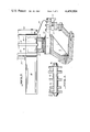
- FIG. 1 is a front elevation of continuous motion can decorating apparatus including contour feed means contructed in accordance with teachings of the instant invention.
- FIG. 2 is an enlarged fragmentary portion of FIG. 1 in the region of the contour feed means.
- FIGS. 3, 4, 5 and 6 are cross-sections taken through the respective arrows 3--3, 4--4, 5--5 and 6--6 of FIG. 2 looking in the directions of the respective arrows, 3--3, 4--4, 5--5 and 6--6.
- FIG. 7 is a diagram illustrating an idealized form embodying salient features of the instant invention.
- FIGS. 8 and 9 are cross-sections of the infeed chute taken through the respective lines 8--8 and 9--9 of FIG. 1 looking in the directions of the respective arrows 8--8 and 9--9.
- FIG. 1 illustrates continuing motion cylindrical container decorating apparatus of the general type described in U.S. Pat. No. 4,140,053, issued Feb. 20, 1979, to J. P. Skrypek et al. for a Mandrel Mounting and Trip Mechanism For Continuous Motion Decorator.
- the apparatus of FIG. 1 includes infeed conveyor 15 which receives cans 16, open at one end thereof, from a supply (not shown) and places them in arcuate cradles or pockets 17 along the periphery of spaced rings 13, 14 (FIG. 3) forming the peripheral portion of pocket wheel 12.
- the latter is fixedly secured to carrier wheel 18 which in turn is keyed to continuously rotated horizontal drive shaft 19.
- Horizontal spindles or mandrels 20 are also mounted to wheel 18, with each spindle 20 being in spaced horizontal alignment with an individual pocket 17 in a short region extending downstream from infeed conveyor 15.
- Undecorated cans 16 are transferred from each cradle 17 to a mandrel 20 by an individual spring arm 42 mounted on slide 43 which is driven horizontally through the action of stationary cam 44 and followers 45, 46 secured to slide 43. Suction applied through an axial passage extending to the end of mandrel 20 which receives container 16 draws the latter to final seating position on mandrel 20.
- cans 16 While mounted on mandrels 20, cans 16 are decorated by being brought into engagement with continuously rotating image transfer mat or blanket 21 of the multicolor printing press indicated generally by reference numeral 22. Thereafter, and while still mounted on mandrels 20, each decorated can 16 has a protective film of varnish applied thereto by engagement with the periphery of applicator roll 23 in the overvarnish unit indicated generally by reference numeral 24. Cans 16 with decorations and protective coating thereon are then transferred from mandrels 20 to suction cups (not shown) mounted along the periphery of transfer wheel 27. The latter rotates continuously about shaft 28 in the center. Cans 16 carried by transfer wheel 27 are deposited on generally horizontal pins 29 carried by chain-type output conveyor 30 which carries cans 16 through a curing oven (not shown).
- Each mandrel 20 is loaded with a can 16 by the time mandrel 20 is in the proximity of sensors 63, 64 which detect whether the particular mandrel 20 contains a properly mounted can 16. If sensors 38, 39 detect that a mandrel 20 is unloaded or is not properly loaded, as this mandrel 20 passes through the decorating zone wherein printing blanket 21 normally engages cans 16 on mandrels 20, as explained in the aforesaid U.S. Pat. No. 4,140,053, this misloaded mandrel 20 is moved to a "no-print" position wherein as this mandrel 20 moves through the decorating zone it will be spaced from the periphery of blanket 21.
- infeed conveyor 15 is constructed of interior plates 51, 52 and 53 and outer plates 54, 55 maintained in spaced parallel relationship by four assemblies each of which consists of stud 56, spacer sleeves 57, 58, 59, 60, lock washer 61 and nut 62 (FIG. 4).
- Four posts extend horizontally from the machine frame and are received by aligned apertures in plates 51-55 to operatively position conveyor 15. Collars 64, 65 operatively position and lock conveyor 15 on pins 63.
- Inner plates 51, 52, 53 are provided with horizontally aligned curved slots which cooperate to form feed chute section 70 through which cans 16a, 16b, etc. flow into pockets 17 of pocket wheel 12.
- the axes of cans 16a, 16b, etc. are horizontal and perpendicular to the flow direction.
- ring 13 runs through the space between plates 51, 52 and ring 14 runs through the space between plates 52, 53 (FIG. 3).
- inner plates 51-53 provide arcuate retaining surface 99 which is slightly outboard of cans 16 being carried upward by pocket wheel 12.
- the spacing between the upstream end of surface 99 and can 16a which has just left chute 70 is substantially greater than spacing between surface 99 and cans downstream of can 16a. This increased spacing is provided to prevent damage to can 16a as its direction of motion changes abruptly at loading region 71 at which time there may be a tendency for can 16a to jump upward which is not under control.
- readily yieldable resilient means constituted by brush sections 97, 98 (FIG. 6), is provided as an abutment to maintain can 16a seated on pocket wheel 12 at loading region 71.
- the bristles of both brush sections 97, 98 are arranged in a triangular configuration radiating from rod 96.
- the latter is pivotally mounted to plates 51 and 55 and is held in a selected angular position by locking device 95 having manual operating handle 94.
- pocket wheel 12 is shown in its angular position wherein can 16a has just been fully seated in pocket 17a.
- lead-in surface 75 between pocket 17a and adjacent upstream pocket 17b is a circular arc tangent to both pockets 17a and 17b.
- the centers of cans 16a, 16b are connected by a line which extends through the center about which lead-in surface 75 is formed.
- the center about which lead-in arc 75 is formed is located on one or the other of two quadrature lines described with reference to FIG. 7 in which point b is the center about which lead-in surface 75 is formed.
- Point b is located on quadrature line q extending through the rotational axis 19 of pocket wheel 12.
- Line q is also perpendicular to the other quadrature line extending through center 19 and the center c about which the arc segment forming upstream pocket 17b is formed.
- the centers of all pockets 17 are uniformly space along a circle of pitch radius a so that the angular spacing ⁇ between adjacent pockets 360° divided by the number of pockets.
- Line s is parallel to line p so that the former is perpendicular to line q.
- wheel 12 has 24 equally spaced pockets 17 on a pitch radius of 20 inches.
- can 16a becomes fully seated in pocket 17a
- can 16b in chute 70 upstream of can 16a engages the latter at point t where the arc of lead-in surface 75 is tangent to the arc of pocket 17a.
- center f of can 16b is on a line extending through points b, e and t.
- the extreme downstream end 85 of lead-in surface 75 is connected with the pocket arc 17 by a curve of small radius rather than by a sharp tip section. This assures smooth engagement between a can, such as can 16b, leaving chute 70 and engaging lead-in surface 75.
- Short portion 75a at the downstream end of lead-in surface 75 is slightly undercut to provide clearance as lead-in surface 75 initially contacts can 16b so as to reduce the likelihood that can 16b will, even momentarily, be pushed away from pocket wheel 12.
- the radius of downstream end 85 as well as the extent and shape of undercut portion 75a are primarily functions of can diameter and top can feed rate.
- a contour chute constructed and positioned in accordance with teachings of the instant invention to feed cans directly to a pocket wheel constructed in accordance with the instant invention enables feeding to occur at speeds substantially in excess of 1,000 cans per minute. Because there is essentially continuous can flow at uniform speed within the chute the likelihood of jams and/or can damage is substantially reduced as compared to gravity or other types of prior art feeders.
- chute portion 110 of infeed 15 is defined by six half round hollow relatively low friction plastic guide strips 101 each having a metal stiffening strip 102 extending therethrough.
- Guide strips 101 extend through and are secured to a plurality of rectangular frames 103 spaced along the length of the chute portion 110 and secured to a rigid framework (not shown).
- a nut 104 and screw 105 secure the individual guide strips 101 to each frame 103.
- chute portion 110 As in chute portion 70, cans 16 are oriented with their cylindrical axes horizontal. However, further upstream, at chute portion 120 the cylindrical axes of cans 16 are generally vertical. As seen in FIG. 8, chute portion 120 is also constructed of six half round hollow low friction plastic guide strips 111 each having a metal stiffening strip 112 extending therethrough. Guide strips 111 extend through rectangular frames 113 (only one of which is shown) and are secured thereto by screws 114 threadably engaged by nuts 115.
- chute section 120 is connected to the upstream end of chute section 110 by transition chute section 125 which is constructed, in a manner well known to the art, to pivot the axis of each can 16 from a generally vertical position as it leaves chute section 120 to a horizontal position as it enters chute section 110. Extending a substantial portion of the length of chute section 120 is the upper flight of closed loop belt 127 which is continuously driven in the direction indicated by arrow D in FIG. 1.
- Belt 127 has a stranded metal interior covered by a plastic coating which is in a frictional driving engagement with the bottom of cans 16 to positively move them downstream.
- Pulley 150 drives belt 127 at a speed greater than that required to move cans 16 through conveyor 15 at the rate cans 16 are demanded by pocket wheel 12.
- This overspeed results in slippage between belt 127 and some of the cans 16 in chute section 120.
- this overspeed assures that belt 127 will always apply a positive mechanical force in a downstream direction against those cans 16 in the portions of chute 15 downstream of friction drive belt 127.
- This positive downstream force results in improved can loading at extremely high peripheral speeds for pocket wheel 12 in that it assures that the rate of can movement through the downstream end of chute 15 will be sufficiently great to make a can 16a available for loading in each of the pockets 17 of wheel 12.
- the speed of drive pulley 150 may be coordinated with that of wheel 12 either by setting the latter to operate at a speed great enough to deliver a sufficient number of cans 16 to wheel 12 even when the latter is operating at top speed or by having an electrical or mechanical coupling which operates so that pulley 150 and wheel 12 automatically speed up and slow down together.
Landscapes
- Specific Conveyance Elements (AREA)
- Chutes (AREA)
Priority Applications (11)
| Application Number | Priority Date | Filing Date | Title |
|---|---|---|---|
| US06/064,491 US4458804A (en) | 1977-08-12 | 1979-08-07 | Contour in-feed means for continuous motion can decorator |
| CA000357127A CA1148983A (en) | 1979-08-07 | 1980-07-28 | Contour in-feed means for continuous motion can decorator |
| ZA00804564A ZA804564B (en) | 1979-08-07 | 1980-07-28 | Contour in-feed means for continuous motion can decorator |
| GB8025363A GB2056398B (en) | 1979-08-07 | 1980-08-04 | Container rotary infeed apparatus |
| AU61032/80A AU6103280A (en) | 1979-08-07 | 1980-08-04 | Can decorator |
| ES494049A ES8105664A1 (es) | 1979-08-07 | 1980-08-06 | Aparato alimentador de envases a una polea, de cadena en mo-vimiento continuo. |
| DE19803029804 DE3029804A1 (de) | 1979-08-07 | 1980-08-06 | Dosenzufuhrvorrichtung fuer eine kontinuierlich arbeitende dosenbedruckungsmaschine |
| SE8005561A SE8005561L (sv) | 1979-08-07 | 1980-08-06 | Anordning for matning av behallare |
| FR8017457A FR2463083A1 (fr) | 1979-08-07 | 1980-08-07 | Dispositif d'alimentation en conteneurs cylindriques, notamment pour machine a imprimer ces conteneurs |
| JP10879080A JPS5637922A (en) | 1979-08-07 | 1980-08-07 | Can feeder for continuous operation can ornamental device |
| NL8004510A NL8004510A (nl) | 1979-08-07 | 1980-08-07 | Inrichting voor het bedrukken van cylindrische voorwerpen. |
Applications Claiming Priority (2)
| Application Number | Priority Date | Filing Date | Title |
|---|---|---|---|
| US82398077A | 1977-08-12 | 1977-08-12 | |
| US06/064,491 US4458804A (en) | 1977-08-12 | 1979-08-07 | Contour in-feed means for continuous motion can decorator |
Related Parent Applications (1)
| Application Number | Title | Priority Date | Filing Date |
|---|---|---|---|
| US82398077A Continuation-In-Part | 1977-08-12 | 1977-08-12 |
Publications (1)
| Publication Number | Publication Date |
|---|---|
| US4458804A true US4458804A (en) | 1984-07-10 |
Family
ID=22056361
Family Applications (1)
| Application Number | Title | Priority Date | Filing Date |
|---|---|---|---|
| US06/064,491 Expired - Lifetime US4458804A (en) | 1977-08-12 | 1979-08-07 | Contour in-feed means for continuous motion can decorator |
Country Status (11)
| Country | Link |
|---|---|
| US (1) | US4458804A (oth) |
| JP (1) | JPS5637922A (oth) |
| AU (1) | AU6103280A (oth) |
| CA (1) | CA1148983A (oth) |
| DE (1) | DE3029804A1 (oth) |
| ES (1) | ES8105664A1 (oth) |
| FR (1) | FR2463083A1 (oth) |
| GB (1) | GB2056398B (oth) |
| NL (1) | NL8004510A (oth) |
| SE (1) | SE8005561L (oth) |
| ZA (1) | ZA804564B (oth) |
Cited By (3)
| Publication number | Priority date | Publication date | Assignee | Title |
|---|---|---|---|---|
| US4921093A (en) * | 1988-05-09 | 1990-05-01 | Sequa Corporation | Infeed means for high speed continuous motion can decorator |
| US20070256911A1 (en) * | 2004-03-05 | 2007-11-08 | Sidel Participations | Conveyor Device with an Improved Transfer Arm |
| CN112020304A (zh) * | 2018-04-20 | 2020-12-01 | Gea食品策划韦尔特公司 | 用于棒棒糖成形机的改良棒体供应单元 |
Families Citing this family (2)
| Publication number | Priority date | Publication date | Assignee | Title |
|---|---|---|---|---|
| DE3637694A1 (de) * | 1986-11-05 | 1988-05-19 | Krupp Corpoplast Masch | Vorrichtung zur uebergabe von vorformlingen von einer foerderstrecke auf ein aufnahmerad |
| DE4327972C1 (de) * | 1993-08-19 | 1994-10-20 | Herlan & Co Maschf | Verfahren zum Steuern des Anhaltens eines Druckwerkes einer Tuben- bzw. Dosenbedruckmaschine |
Citations (8)
| Publication number | Priority date | Publication date | Assignee | Title |
|---|---|---|---|---|
| US1397990A (en) * | 1920-10-13 | 1921-11-22 | Anderson Barngrover Mfg Co | Can-extractor |
| US2339008A (en) * | 1940-11-27 | 1944-01-11 | Crown Cork & Seal Co | Coating machine |
| US2874701A (en) * | 1954-03-31 | 1959-02-24 | Koerber & Co Kg | Guiding system on machines for producing filter tip cigarettes |
| US2919801A (en) * | 1956-12-10 | 1960-01-05 | American Can Co | Machine for treating and sorting can bodies |
| US3503488A (en) * | 1967-03-03 | 1970-03-31 | Molins Machine Co Ltd | Article feeding apparatus and method |
| US3722663A (en) * | 1971-06-14 | 1973-03-27 | Nalbach J Eng Co Inc | Stabilizing apparatus for lightweight containers |
| US3944048A (en) * | 1975-04-02 | 1976-03-16 | Gennady Ivanovich Grishaev | Mechanism for loading lamp caps into the cells of an endless chain conveyor |
| US4140053A (en) * | 1977-06-16 | 1979-02-20 | Sun Chemical Corporation | Mandrel mounting and trip mechanism for continuous motion decorator |
Family Cites Families (1)
| Publication number | Priority date | Publication date | Assignee | Title |
|---|---|---|---|---|
| MX148336A (es) * | 1977-08-12 | 1983-04-13 | Sun Chemical Corp | Mejoras en aparato para decorar envases a alta velocidad |
-
1979
- 1979-08-07 US US06/064,491 patent/US4458804A/en not_active Expired - Lifetime
-
1980
- 1980-07-28 ZA ZA00804564A patent/ZA804564B/xx unknown
- 1980-07-28 CA CA000357127A patent/CA1148983A/en not_active Expired
- 1980-08-04 GB GB8025363A patent/GB2056398B/en not_active Expired
- 1980-08-04 AU AU61032/80A patent/AU6103280A/en not_active Abandoned
- 1980-08-06 SE SE8005561A patent/SE8005561L/ not_active Application Discontinuation
- 1980-08-06 ES ES494049A patent/ES8105664A1/es not_active Expired
- 1980-08-06 DE DE19803029804 patent/DE3029804A1/de not_active Ceased
- 1980-08-07 FR FR8017457A patent/FR2463083A1/fr active Granted
- 1980-08-07 JP JP10879080A patent/JPS5637922A/ja active Pending
- 1980-08-07 NL NL8004510A patent/NL8004510A/nl not_active Application Discontinuation
Patent Citations (8)
| Publication number | Priority date | Publication date | Assignee | Title |
|---|---|---|---|---|
| US1397990A (en) * | 1920-10-13 | 1921-11-22 | Anderson Barngrover Mfg Co | Can-extractor |
| US2339008A (en) * | 1940-11-27 | 1944-01-11 | Crown Cork & Seal Co | Coating machine |
| US2874701A (en) * | 1954-03-31 | 1959-02-24 | Koerber & Co Kg | Guiding system on machines for producing filter tip cigarettes |
| US2919801A (en) * | 1956-12-10 | 1960-01-05 | American Can Co | Machine for treating and sorting can bodies |
| US3503488A (en) * | 1967-03-03 | 1970-03-31 | Molins Machine Co Ltd | Article feeding apparatus and method |
| US3722663A (en) * | 1971-06-14 | 1973-03-27 | Nalbach J Eng Co Inc | Stabilizing apparatus for lightweight containers |
| US3944048A (en) * | 1975-04-02 | 1976-03-16 | Gennady Ivanovich Grishaev | Mechanism for loading lamp caps into the cells of an endless chain conveyor |
| US4140053A (en) * | 1977-06-16 | 1979-02-20 | Sun Chemical Corporation | Mandrel mounting and trip mechanism for continuous motion decorator |
Cited By (6)
| Publication number | Priority date | Publication date | Assignee | Title |
|---|---|---|---|---|
| US4921093A (en) * | 1988-05-09 | 1990-05-01 | Sequa Corporation | Infeed means for high speed continuous motion can decorator |
| EP0341982A3 (en) * | 1988-05-09 | 1990-11-22 | Sequa Corporation | High speed can decorator |
| US20070256911A1 (en) * | 2004-03-05 | 2007-11-08 | Sidel Participations | Conveyor Device with an Improved Transfer Arm |
| US7451868B2 (en) * | 2004-03-05 | 2008-11-18 | Sidel Participations | Conveyor device with an improved transfer arm |
| CN100591594C (zh) * | 2004-03-05 | 2010-02-24 | 西德尔合作公司 | 具有传送臂的输送装置 |
| CN112020304A (zh) * | 2018-04-20 | 2020-12-01 | Gea食品策划韦尔特公司 | 用于棒棒糖成形机的改良棒体供应单元 |
Also Published As
| Publication number | Publication date |
|---|---|
| CA1148983A (en) | 1983-06-28 |
| GB2056398B (en) | 1983-06-29 |
| FR2463083B3 (oth) | 1982-06-11 |
| JPS5637922A (en) | 1981-04-11 |
| NL8004510A (nl) | 1981-02-10 |
| AU6103280A (en) | 1981-02-12 |
| FR2463083A1 (fr) | 1981-02-20 |
| DE3029804A1 (de) | 1981-02-26 |
| ES494049A0 (es) | 1981-07-01 |
| ES8105664A1 (es) | 1981-07-01 |
| SE8005561L (sv) | 1981-02-08 |
| ZA804564B (en) | 1982-02-24 |
| GB2056398A (en) | 1981-03-18 |
Similar Documents
| Publication | Publication Date | Title |
|---|---|---|
| US5709770A (en) | Apparatus for decorating articles via heat transfer labelling | |
| US5231926A (en) | Apparatus and method for substantially reducing can spacing and speed to match chain pins | |
| US11745517B2 (en) | Container decoration apparatus and method | |
| EP0134158B1 (en) | Base coat applicator | |
| US3116193A (en) | Method of applying labels | |
| US4458804A (en) | Contour in-feed means for continuous motion can decorator | |
| US4921093A (en) | Infeed means for high speed continuous motion can decorator | |
| US5183145A (en) | Apparatus and method for automatically positioning valve means controlling the application of pressurized air to mandrels on a rotating carrier | |
| CA1090840A (en) | Contour in-feed means for continuous motion can decorator | |
| US3300019A (en) | Transfer assembly for use with high speed can decorating machines | |
| US4592276A (en) | Printing machine with curing system | |
| US4587926A (en) | Bottom rim coater for intermittently operated container decorating apparatus | |
| US4009776A (en) | Can unloader |
Legal Events
| Date | Code | Title | Description |
|---|---|---|---|
| STCF | Information on status: patent grant |
Free format text: PATENTED CASE |
|
| AS | Assignment |
Owner name: SEQUA CORPORATION Free format text: CHANGE OF NAME;ASSIGNOR:SUN CHEMICAL CORPORATION, A CORP. OF DE.;REEL/FRAME:004770/0239 Effective date: 19870507 |
|
| AS | Assignment |
Owner name: BANK OF NEW YORK, THE, NEW YORK Free format text: SECURITY INTEREST;ASSIGNOR:SEQUA CORPORATION;REEL/FRAME:006554/0944 Effective date: 19930524 |
|
| AS | Assignment |
Owner name: SEQUA CORPORATION, NEW YORK Free format text: SECURITY INTEREST RELEASE;ASSIGNOR:BANK OF NEW YORK, THE;REEL/FRAME:012083/0764 Effective date: 20010810 |