US4433862A - Pipe joint - Google Patents
Pipe joint Download PDFInfo
- Publication number
- US4433862A US4433862A US06/456,526 US45652683A US4433862A US 4433862 A US4433862 A US 4433862A US 45652683 A US45652683 A US 45652683A US 4433862 A US4433862 A US 4433862A
- Authority
- US
- United States
- Prior art keywords
- seal
- pipe
- box
- pipe joint
- thread
- Prior art date
- Legal status (The legal status is an assumption and is not a legal conclusion. Google has not performed a legal analysis and makes no representation as to the accuracy of the status listed.)
- Expired - Fee Related
Links
Images


Classifications
-
- F—MECHANICAL ENGINEERING; LIGHTING; HEATING; WEAPONS; BLASTING
- F16—ENGINEERING ELEMENTS AND UNITS; GENERAL MEASURES FOR PRODUCING AND MAINTAINING EFFECTIVE FUNCTIONING OF MACHINES OR INSTALLATIONS; THERMAL INSULATION IN GENERAL
- F16L—PIPES; JOINTS OR FITTINGS FOR PIPES; SUPPORTS FOR PIPES, CABLES OR PROTECTIVE TUBING; MEANS FOR THERMAL INSULATION IN GENERAL
- F16L15/00—Screw-threaded joints; Forms of screw-threads for such joints
- F16L15/001—Screw-threaded joints; Forms of screw-threads for such joints with conical threads
- F16L15/004—Screw-threaded joints; Forms of screw-threads for such joints with conical threads with axial sealings having at least one plastically deformable sealing surface
-
- E—FIXED CONSTRUCTIONS
- E21—EARTH DRILLING; MINING
- E21B—EARTH DRILLING, e.g. DEEP DRILLING; OBTAINING OIL, GAS, WATER, SOLUBLE OR MELTABLE MATERIALS OR A SLURRY OF MINERALS FROM WELLS
- E21B17/00—Drilling rods or pipes; Flexible drill strings; Kellies; Drill collars; Sucker rods; Cables; Casings; Tubings
- E21B17/02—Couplings; joints
- E21B17/04—Couplings; joints between rod or the like and bit or between rod and rod or the like
- E21B17/042—Threaded
-
- F—MECHANICAL ENGINEERING; LIGHTING; HEATING; WEAPONS; BLASTING
- F16—ENGINEERING ELEMENTS AND UNITS; GENERAL MEASURES FOR PRODUCING AND MAINTAINING EFFECTIVE FUNCTIONING OF MACHINES OR INSTALLATIONS; THERMAL INSULATION IN GENERAL
- F16L—PIPES; JOINTS OR FITTINGS FOR PIPES; SUPPORTS FOR PIPES, CABLES OR PROTECTIVE TUBING; MEANS FOR THERMAL INSULATION IN GENERAL
- F16L15/00—Screw-threaded joints; Forms of screw-threads for such joints
- F16L15/001—Screw-threaded joints; Forms of screw-threads for such joints with conical threads
- F16L15/003—Screw-threaded joints; Forms of screw-threads for such joints with conical threads with sealing rings
-
- F—MECHANICAL ENGINEERING; LIGHTING; HEATING; WEAPONS; BLASTING
- F16—ENGINEERING ELEMENTS AND UNITS; GENERAL MEASURES FOR PRODUCING AND MAINTAINING EFFECTIVE FUNCTIONING OF MACHINES OR INSTALLATIONS; THERMAL INSULATION IN GENERAL
- F16L—PIPES; JOINTS OR FITTINGS FOR PIPES; SUPPORTS FOR PIPES, CABLES OR PROTECTIVE TUBING; MEANS FOR THERMAL INSULATION IN GENERAL
- F16L15/00—Screw-threaded joints; Forms of screw-threads for such joints
- F16L15/04—Screw-threaded joints; Forms of screw-threads for such joints with additional sealings
Definitions
- This invention relates to pipe joints and more particularly to joints to be used downhole in a producing well.
- the invention may be used with drill pipe, tubing or a casing, all of which are referred to herein as "pipe”.
- connections must be developed that utilize as many of the required features of the pipe, while sacrificing as few features as possible.
- the desired features are that the connections develop full pipe strength and tensile strength, internal pressure rating, and collapse rating.
- the connection should also be able to withstand high temperatures and/or bending.
- the pipe joint is designed such that the box of the joint will have approximately the same internal pressure rating at the point of maximum metal-to-metal seal, that is, resistance to ballooning, as does the full wall thickness of the pipe between a pair of connectors.
- the thread system may be designed without regard to the seal surfaces between pipe and box and a step surface may joint the metal-to-metal seal system and the thread system.
- the pipe joint is designed such that a resilient or plastic seal may be utilized.
- a plastic material inert to well fluids which must be compressed to be effective, the invention provides for maintaining such material under compression without the plastic seal interfering with the normal engagement and sealing function of the metal-to-metal seal.
- Another object is to provide a pipe joint in which the resistance to ballooning of the box at the maximum diameter of the metal-to-metal seal is at least equal to the resistance to ballooning of the pipe being connected together and the thread system may be designed for optimum strength without regard to the metal-to-metal seal.
- Another object is to provide a pipe joint of the type having a metal-to-metal seal between the box and an external surface on the pipe in conjunction with a back-up seal of plastic material.
- Another object is to provide a pipe joint having a metal-to-metal seal with a back-up seal of compressible material in which the material is placed under compression without interfering with the normal engagement and sealing of the metal-to-metal seal surfaces.
- Another object is to provide a pipe joint having a metal-to-metal seal in conjunction with a back-up seal of compressible material in which, as the joint is made up, excess compressible material is extruded from the zone of the back-up seal until just before final make-up of the joint at which time the compressible material is confined and placed in compression during final make-up and in which means are provided for receiving the extruded material so that it will not reach the primary metal-to-metal sealing surfaces and possible interfere with their normal engagement and sealing functions.
- Another object is to provide a pipe joint of the type having a primary metal-to-metal seal with a back-up seal of compressible material in which, as the joint is made up, excess compressible material is extruded from the back-up seal area after which a secondary metal-to-metal seal becomes effective to act as a secondary metal-to-metal seal for the joint and to confine the compressible material against further extrusion so that as the joint is finally made up, the material may be placed under substantial compression.
- Another object is to provide a pipe joint as in the preceding object in which means are provided for receiving the extruded seal material so that it will not reach the area of the primary metal-to-metal seal and possibly interfere with full make-up and sealing of the metal-to-metal seal.
- a pipe joint constructed in accordance with this invention will have a wall thickness at the greatest diameter section of the metal-to-metal seal such that this thickness relative to the diameter of the box is equal to or slightly greater than the ratio of the full wall thickness of the pipe to the diameter of the pipe.
- FIG. 1 is a quarter-section view of a pipe joint including a coupling between two pipes;
- FIG. 2 is a fragmentary view on an enlarged scale of a modified form of pipe joint
- FIGS. 3, 4 and 5 are fragmentary quarter-section views showing sequentially the makeup of the pipe joint of FIG. 1;
- FIGS. 6 and 7 are fragmentary quarter-section views showing sequentially the makeup of the pipe joint of FIG. 2;
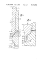
- FIGS. 8, 9 and 10 are sectional views of the modified pipe joint of FIGS. 8a and 10a, showing in FIG. 8, the condition of the seal system prior to engagement of the compressible material by the pin thread, and in FIG. 9, the seal material being extruded past the secondary seal during make-up, and in FIG. 10, the fully made-up joint with extruded material contained within the excess seal groove.
- FIG. 8a is a fragmentary sectional view on an enlarged scale of a modified form of pipe joint of FIGS. 8, 9 and 10 in which a compressible member provides a back-up seal; prior to the pin threads engaging the compressible material;
- FIG. 10a is a view similar to FIG. 8a showing the pipe joint in fully made-up position with the seal material under compression and with excess seal material which was extruded during make-up contained within an excess seal groove and the primary and secondary metal seals in sealing engagement;
- the pipe 10 is provided with an external tapered thread 11 thereon.
- this thread is of the buttress type having its load bearing surface extending substantially normal to the center line of the pipe.
- the taper of the threads may be that normally used, that is on the order of three-quarters of an inch per foot. In many instances, where very heavy wall pipe is used, it will be preferred to use a larger taper such as one and one-quarter inch per foot.
- the use of the steeper taper permits a shorter threaded section of the pipe and box of the coupling. The shorter threaded section in turn reduces the overall length of the coupling and permits greater control and accuracy in cutting threads and other surfaces.
- a smaller diameter surface 13 Adjacent the smaller diameter end of thread 11, the outer diameter of the pipe steps down at 12 to a smaller diameter surface 13 which may be smaller than the diameter of the smallest box thread.
- This surface 13 is a sealing surface and extends annually about the pipe and longitudinally for a short distance adjacent the end of the pipe. This surface 13 should be contoured to result in a firm sealing contact with the box of the coupling when the joint is made up. For instance, the surface may be on a slight taper or it may be on a radius to provide the sealing contact.
- the pipe is stressed radially outwardly to ensure the sealing characteristics of the surface 13 and for this purpose, the end of the pipe 14 forms an acute angle with the surface 13.
- the sealing surface 13 may be formed on an angle slightly less than 3° and the abutment surface 14 on an angle of approximately 15°.
- the box 15 of the coupling will have an internal thread 16 complementary to and mating with the thread 11 on the pipe.
- the box will step down at 17 to a smaller diameter sealing surface 18 which sealingly engages with the sealing surface 13 on the pipe.
- the box is provided with a torque shoulder 19 extending inwardly from the seal surface 18 to the bore 21 through the coupling.
- the shoulder 19 should have a matching taper with the shoulder 14 on the end of the pipe which when the pipe is bottomed in the box, limits makeup of the pipe and box and preferably, due to its inclined surface, urges the pipe toward sealing position between the surfaces 13 and 18 which provide the primary seal.
- the torque shoulder 19 and the end of the pipe 14 may provide a seal, particularly against external pressure.
- the surfaces 13 and 18 should seal along their entire engaged length. Due to the slight taper of the surfaces, the maximum diameter point of sealing engagement is their point of engagement remote from the abutment shoulder 19. This is the point of last metal-to-metal sealing engagement against pressure within the tubing.
- the box is designed such that its strength at this point of maximum sealing diameter resistant to ballooning is equal to or greater than the strength of the pipe to resist ballooning.
- the wall thickness (tb) of the box at the point of maximum diameter of the engaged and sealing surfaces 13 and 18 relative to the outer diameter (Db) of the coupling is approximately equal to or greater than the ratio of the full wall thickness of the pipe (tp) relative to the outer diameter of the pipe (Dp) so that the box will be as resistant to ballooning under internal pressure as will the pipe. This will prevent ballooning of the coupling and the possible resultant disengagement of the threads 11 and 16.
- the seal provided by surfaces 13 and 18 remains effective, there should be no danger of the threads disengaging due to ballooning of the coupling.
- the internal diameter flange 20 results in a larger tb measured at the flange.
- the flange supports the sealing surfaces against ballooning, resulting in the coupling having a greater t/D ratio than the pipe.
- a resilient seal is provided by a plastic ring 22 in the groove 23 in the box.
- This ring is preferably of a plastic material such as tetrafluoroethylene.
- the groove 23 is positioned such that as the pipe is rotated to full make-up position, the small diameter end of thread of thread 11 enters the area of groove 22 and places the ring under substantial compression.
- the pipe has an annular surface 24 below thread 11 which overlies the seal 22 before the thread 11 begins to compress the seal 22.
- the surface 24 on the pipe is spaced a slight distance from the complementary surface 25 in the box so that the plastic material would be permitted to flow under pressure into the space thus provided.
- the seal material forced into the space between surfaces 24 and 25 provides a primary plastic seal backed up by seal material in the thread 11 and groove 23. This plastic seal provides a back-up for the metal-to-metal seals.
- a bleed port 26 may be provided in the box, preferably immediately adjacent the resilient seal 22 so that any leakage of fluid past the seals would be vented to the exterior of the joint and would not cause ballooning of the threaded section of the box.
- the surfaces 18 could be extended away from the torque shoulder 19 and a groove provided in this extended surface for the plastic seal. If the step 17 was of substantial dimension, this would position the plastic seal immediately adjacent the metal-to-metal seal and the value of tb would be approximately the same for the metal-to-metal seal and for the plastic seal.
- the relative area of the torque shoulder 19 and the makeup torque should be such that the induced pressure on the shoulder 19 is substantially greater than the internal pressure to be sealed against. For deep high pressure wells, this induced pressure might be on the order of 30,000 to 50,000 psi.
- FIGS. 3, 4 and 5 show the makeup of the pipe and box of FIG. 1.
- the pipe 10 has been threaded into the box 15 to the point where the surface 24 overlies the seal 22 to hold it in its groove during final makeup.
- the pipe 10 is shown to be inserted into the box 15 to the extent that the seal 22 has been extruded into the space between the surfaces 24 and 25 and the sealing surfaces 13 and 18 are beginning their makeup.
- the pipe 10 is shown to be in the final fully sealed position in the box with the nose of the pipe in firm engagement with the torque shoulder 18 and the pipe makeup preferably to exert a pressure per square inch against the torque shoulder greater than the pressure within the tubing.
- pipe 27 is identical to pipe 10 and that the coupling is symmetrical and is identical below the flange 20 to the portion of coupling shown above flange 20.
- FIGS. 2, 6 and 7. A modified form of the invention is shown in FIGS. 2, 6 and 7.
- the pipe 28 is formed with the seal surface 13 and an additional seal surface 29 which cooperates with the end surface 31 of the pipe to form a V-shaped annular member.
- the surfaces 31 and 29 mate with complementary torque shoulders 32 and seal surface 33 in the box 34.
- seals occur at the torque shoulder 31-32, at the seal surface 28 and 33, and at the seal surface 13 and 18.
- the box is provided with a groove 35 adjacent the upper end of seal surface 18 and again a seal of plastic material 36 is provided in this groove.
- tb would be measured in the coupling immediately adjacent the groove 35 on the side of the seal groove adjacent to the torque shoulder 31 as the largest point of metal-to-metal seal occurs at this point.
- the value of tb at the point of seal of the plastic seal would be only slightly larger than the value of tb at the metal-to-metal seal; thus the coupling at the plastic seal would be as resistant to ballooning as would be the pipe 28, and the coupling would not balloon at the point of the plastic seal to any appreciable extent. This is particularly true in view of the fact that the flange 37 is again supporting the seals and the resistance of the coupling to ballooning in view of the support of the flange would actually be greater than the resistance of the tubing to ballooning.
- the t/D of the coupling is preferably equal to that of the pipe.
- the t/D ratio of the coupling need only approximate that of the pipe.
- the t/D ratio of the coupling may be slightly less than that of the pipe at the point of maximum sealing diameter because of the support of the flange for the sealing surface which would make the coupling stronger than the pipe if the t/D ratio of the coupling were equal to that of the pipe.
- the t/D ratio may be slightly greater in the coupling relative to the pipe as this provides additional strength and might be preferred where the torque shoulder and its associated flange are not utilized.
- the invention encompasses a provision of a t/D ratio in the coupling which is approximately the t/D ratio of the pipe.
- the amount of metal in the coupling measured at the plastic seal groove is preferably at least equal to the amount of metal in the pipe measured at the full wall thickness of the pipe.
- FIGS. 8 through 10, 8a and 10a a modified form of joint is shown which employs a compressible back-up seal.
- the box 15 is provided at the last thread with a seal receiving groove 23a and a seal member 22a of compressible material.
- the well fluids being produced are such that they can be sealed against only by special materials which are not subject to attack by the well fluids.
- a seal material primarily or entirely of tetrafluoroethylene, commonly known by its trademark Teflon. Teflon will withstand fluids found in many wells and is a desirable seal material.
- Teflon and like materials should be placed under substantial compression and the design of the joint of FIGS. 8 through 10 provide for using a compressible material which may be placed under substantial compression.
- the joint should be made up as is customary with lubricant which will fill and seal between the pin and box threads.
- lubricant which will fill and seal between the pin and box threads.
- the relationship is such that when the joint is made up, the roots and crests, as well as load flanks of the threads 11 and 16 are in substantial engagement with each other.
- the stabbing flanks 11a on the pin and the complimentary flanks 16a, on the box will have a few thousandths of an inch clearance.
- the thread system will not provide an avenue for escape of the seal material 22a when placed in substantial compression and no substantial amount of seal material will be extruded into the thread system during final make-up when the seal material is placed under a substantial compression.
- the seal material 22a is slightly larger in volume than the volume of the groove 23a as defined by the pipe and threads extending into the groove 23a when the joint is fully made up. This excess amount of material is extruded between the surface 24a on the pin and the surface 25a on the box as the pin moves towards final sealing engagement as shown in FIG. 9.
- These secondary seal surfaces 24a and 25a are formed on slightly different tapers so that they may engage and seal with each other in a non-critical manner as the pin moves to its final made-up position shown in FIGS. 10 and 10a.
- the seal material 22a Prior to reaching this position, the seal material 22a will have been placed under compression and extruded through the space between the two secondary seal surfaces 24a and 25a as the pin threads move into and reduce the volume within the groove 23a. The excess seal material will extrude between the two secondary seal surfaces and as the pin is rotating relative to the box, the extruded material will also be torn, usually at a number of places.
- the secondary seal surfaces 24a and 25a will have come into sealing engagement slightly before final make-up of the pin and box and, as additional area of the groove 23a is occupied by the pin thread 11, the seal material 22a will be placed in substantial compression so that it will function with maximum performance as a seal. Also, the surfaces 24a and 25a will now provide not only a seal for confining the compressible material 22a in the groove 23a but will also provide an additional metal-to-metal seal against loss of the fluid being conveyed through the joint.
- this means is a groove 38 positioned between the secondary sealing surfaces 24a and 25a, and the primary sealing surfaces 13 and 18.
- this means is a groove 38 positioned between the secondary sealing surfaces 24a and 25a, and the primary sealing surfaces 13 and 18.
- this means is a groove 38 positioned between the secondary sealing surfaces 24a and 25a, and the primary sealing surfaces 13 and 18.
- excess seal material may be used so that the amount of material and the presence of pipe dope is not critical and the seal material as well as any pipe dope which may be trapped within the groove 23a, may be placed under substantial compression after the secondary seal surfaces 24a and 25a are in engagement. These surfaces provide a means for entrapping the seal material to permit it to be placed under compression as well as providing a secondary metal-to-metal seal against loss of fluid being conveyed through the joint.
- the excess seal groove 38 will trap the extruded seal material and prevent it from reaching the primary seal surfaces 13 and 18. It will be appreciated with this type of seal that a triple seal is provided, that is, the primary seal of surfaces 13 and 18, the secondary seal of surfaces 24a and 25a and the compressed material of seal 22a.
- a bleed port such as port 26 (FIG. 1) may be utilized if desired.
Abstract
Description
Claims (20)
tb/Db=tp/Dp
tb/Db=tp/Dp
Priority Applications (7)
| Application Number | Priority Date | Filing Date | Title |
|---|---|---|---|
| US06/456,526 US4433862A (en) | 1982-04-13 | 1983-01-07 | Pipe joint |
| GB08307376A GB2118658B (en) | 1982-04-13 | 1983-03-17 | Pipe joint |
| CA000424847A CA1194055A (en) | 1982-04-13 | 1983-03-30 | Pipe joint |
| DE19833312528 DE3312528A1 (en) | 1982-04-13 | 1983-04-07 | PIPE CONNECTION |
| IT8353182U IT8353182V0 (en) | 1982-04-13 | 1983-04-12 | JOINTING ELEMENT FOR PIPES PARTICULARLY PIPES FOR WELLS |
| FR8305927A FR2524962B1 (en) | 1982-04-13 | 1983-04-12 | PIPE JOINT |
| IT67401/83A IT1193134B (en) | 1982-04-13 | 1983-04-12 | JOINTING ELEMENT FOR PIPES PARTICULARLY PIPES FOR WELLS |
Applications Claiming Priority (2)
| Application Number | Priority Date | Filing Date | Title |
|---|---|---|---|
| US06/367,952 US4473245A (en) | 1982-04-13 | 1982-04-13 | Pipe joint |
| US06/456,526 US4433862A (en) | 1982-04-13 | 1983-01-07 | Pipe joint |
Related Parent Applications (1)
| Application Number | Title | Priority Date | Filing Date |
|---|---|---|---|
| US06/367,952 Continuation-In-Part US4473245A (en) | 1982-04-13 | 1982-04-13 | Pipe joint |
Related Child Applications (1)
| Application Number | Title | Priority Date | Filing Date |
|---|---|---|---|
| US06/583,176 Continuation-In-Part US4489963A (en) | 1982-04-13 | 1984-02-24 | Pipe joint |
Publications (1)
| Publication Number | Publication Date |
|---|---|
| US4433862A true US4433862A (en) | 1984-02-28 |
Family
ID=27003995
Family Applications (1)
| Application Number | Title | Priority Date | Filing Date |
|---|---|---|---|
| US06/456,526 Expired - Fee Related US4433862A (en) | 1982-04-13 | 1983-01-07 | Pipe joint |
Country Status (6)
| Country | Link |
|---|---|
| US (1) | US4433862A (en) |
| CA (1) | CA1194055A (en) |
| DE (1) | DE3312528A1 (en) |
| FR (1) | FR2524962B1 (en) |
| GB (1) | GB2118658B (en) |
| IT (2) | IT8353182V0 (en) |
Cited By (25)
| Publication number | Priority date | Publication date | Assignee | Title |
|---|---|---|---|---|
| US4538840A (en) * | 1983-01-03 | 1985-09-03 | Delange Richard W | Connector means for use on oil and gas well tubing or the like |
| US4593713A (en) * | 1983-09-20 | 1986-06-10 | Arnold Menshen | Measurement coupling |
| US4624488A (en) * | 1983-12-16 | 1986-11-25 | Hydril Company | Tubular connection |
| US4629455A (en) * | 1984-02-09 | 1986-12-16 | Terumo Kabushiki Kaisha | Medical instrument |
| US4671544A (en) * | 1985-10-15 | 1987-06-09 | Hydril Company | Seal for threaded pipe connection |
| US4703959A (en) * | 1986-02-10 | 1987-11-03 | Hydril Company | Threaded pipe connection with compressible seal ring |
| US4893844A (en) * | 1983-04-29 | 1990-01-16 | Baker Hughes Incorporated | Tubular coupling with ventable seal |
| US4946201A (en) * | 1989-03-08 | 1990-08-07 | Baroid Technology, Inc. | Oil field tubular connection |
| US5007665A (en) * | 1986-12-23 | 1991-04-16 | Cipriano Bovisio | Coupling for well casings |
| US5064224A (en) * | 1989-03-08 | 1991-11-12 | Baroid Technology, Inc. | Oil field tubular connection |
| US5131694A (en) * | 1991-02-26 | 1992-07-21 | Midland Manufacturing Corp. | Joint seal between valve body and removable port |
| US5197769A (en) * | 1988-01-27 | 1993-03-30 | Nwd International, Inc. | Adjustable O-ring port fitting for a hydraulic coupling |
| US5794699A (en) * | 1996-11-27 | 1998-08-18 | Halliburton Energy Services, Inc. | Metal-to-metal sliding side door for wells |
| US5855568A (en) * | 1996-11-22 | 1999-01-05 | Liebel-Flarsheim Company | Angiographic syringe and luer connector |
| US20030184084A1 (en) * | 2002-04-01 | 2003-10-02 | Winship Thomas E. | Replaceable corrosion resistant tool joint seal |
| US6669205B2 (en) | 2001-03-28 | 2003-12-30 | Parker-Hannifin Corporation | Retainer gasket with pressure relief vents |
| US6695357B2 (en) | 2001-03-28 | 2004-02-24 | Parker-Hannifin Corporation | Threaded pipe connection having a retainer gasket with pressure relief vents |
| US20050248153A1 (en) * | 2003-06-06 | 2005-11-10 | Masaaki Sugino | Threaded joint for steel pipes |
| US20070164563A1 (en) * | 2006-01-13 | 2007-07-19 | Arstein Dale C | Fitting for tube or pipe |
| US20070164565A1 (en) * | 2003-05-22 | 2007-07-19 | Evans Merle E | Energizing seal for expandable connections |
| CN100441931C (en) * | 2006-08-02 | 2008-12-10 | 中国海洋石油总公司 | Sealing connection structure between two different heat expansion coefficient pipe materials and its connecting method |
| US20160207814A1 (en) * | 2013-07-31 | 2016-07-21 | Knauf Insulation | Process for manufacturing vitrified material by melting |
| US20160245433A1 (en) * | 2015-02-19 | 2016-08-25 | Arcelormittal Tubular Products | Threaded connection for pipes, such as oil and gas pipes |
| US10612702B2 (en) | 2017-03-03 | 2020-04-07 | Arcelormittal Tubular Products Luxembourg S.A. | Torque shoulder of a premium connection |
| US20220065372A1 (en) * | 2017-03-27 | 2022-03-03 | Ad-Venta | Mixed female connector or port |
Families Citing this family (5)
| Publication number | Priority date | Publication date | Assignee | Title |
|---|---|---|---|---|
| FR2571467B1 (en) * | 1984-10-10 | 1987-03-20 | Vallourec | THREADED JOINT FOR A STEEL TUBE HAVING A THREADED SEALING DEVICE |
| EP0212288A3 (en) * | 1985-08-19 | 1987-06-16 | George M. Raulins | Improved oilfield tubular joint and method of manufacturing |
| FR2587080B1 (en) * | 1985-09-12 | 1989-08-04 | Vallourec | THREADED JOINT FOR STEEL TUBES COMPRISING A SEALING DEVICE LOCATED AT THE THREAD LEVEL |
| DE4120998C1 (en) * | 1991-06-21 | 1992-12-03 | Mannesmann Ag, 4000 Duesseldorf, De | |
| DE4446806C1 (en) * | 1994-12-09 | 1996-05-30 | Mannesmann Ag | Gas-tight pipe connection |
Family Cites Families (14)
| Publication number | Priority date | Publication date | Assignee | Title |
|---|---|---|---|---|
| US1590357A (en) * | 1925-01-14 | 1926-06-29 | John F Penrose | Pipe joint |
| GB539139A (en) * | 1940-09-23 | 1941-08-28 | James Cuthill | Improvements in fluid pressure joints for pipes and other conduits, fittings and the like |
| US2610028A (en) * | 1947-10-25 | 1952-09-09 | James E Smith | Well drilling pipe |
| US2907589A (en) * | 1956-11-05 | 1959-10-06 | Hydril Co | Sealed joint for tubing |
| US3047316A (en) * | 1958-10-01 | 1962-07-31 | Atlas Bradford Company | Packed pin and box drill pipe coupling with means preventing extrusion of packing ring |
| DE1129125B (en) * | 1958-10-01 | 1962-05-10 | Atlas Bradford Company | Downhole linkage |
| NL281831A (en) * | 1961-08-09 | |||
| DE1218378B (en) * | 1963-12-20 | 1966-06-08 | Reed Roller Bit Co | Threaded connection, especially for drill collars |
| US3307860A (en) * | 1965-01-15 | 1967-03-07 | Mobil Oil Corp | Joint for liner-carrying well pipe |
| US3336054A (en) * | 1965-01-15 | 1967-08-15 | Mobil Oil Corp | Liner-carrying well pipe and joint |
| US3811710A (en) * | 1969-11-13 | 1974-05-21 | Pipe Specialties Inc | Sealed tubular joint |
| AR206593A1 (en) * | 1972-03-31 | 1976-08-06 | Kainan Steel Tube Co | STRUCTURE OF COUPLING JOINTS FOR THREADED PIPES, PARTICULARLY PIPES FOR OIL WELLS |
| DE2457541A1 (en) * | 1974-12-03 | 1976-06-16 | Mannesmann Roehren Werke Ag | Seal arrangement - for a screwed joint between two oil field pipes |
| GB1503395A (en) * | 1975-09-19 | 1978-03-08 | Attock Oilfield Equip | Pipe connector |
-
1983
- 1983-01-07 US US06/456,526 patent/US4433862A/en not_active Expired - Fee Related
- 1983-03-17 GB GB08307376A patent/GB2118658B/en not_active Expired
- 1983-03-30 CA CA000424847A patent/CA1194055A/en not_active Expired
- 1983-04-07 DE DE19833312528 patent/DE3312528A1/en not_active Withdrawn
- 1983-04-12 IT IT8353182U patent/IT8353182V0/en unknown
- 1983-04-12 FR FR8305927A patent/FR2524962B1/en not_active Expired
- 1983-04-12 IT IT67401/83A patent/IT1193134B/en active
Cited By (31)
| Publication number | Priority date | Publication date | Assignee | Title |
|---|---|---|---|---|
| US4538840A (en) * | 1983-01-03 | 1985-09-03 | Delange Richard W | Connector means for use on oil and gas well tubing or the like |
| US4893844A (en) * | 1983-04-29 | 1990-01-16 | Baker Hughes Incorporated | Tubular coupling with ventable seal |
| US4593713A (en) * | 1983-09-20 | 1986-06-10 | Arnold Menshen | Measurement coupling |
| US4624488A (en) * | 1983-12-16 | 1986-11-25 | Hydril Company | Tubular connection |
| US4629455A (en) * | 1984-02-09 | 1986-12-16 | Terumo Kabushiki Kaisha | Medical instrument |
| US4671544A (en) * | 1985-10-15 | 1987-06-09 | Hydril Company | Seal for threaded pipe connection |
| US4703959A (en) * | 1986-02-10 | 1987-11-03 | Hydril Company | Threaded pipe connection with compressible seal ring |
| US5007665A (en) * | 1986-12-23 | 1991-04-16 | Cipriano Bovisio | Coupling for well casings |
| US5197769A (en) * | 1988-01-27 | 1993-03-30 | Nwd International, Inc. | Adjustable O-ring port fitting for a hydraulic coupling |
| US5064224A (en) * | 1989-03-08 | 1991-11-12 | Baroid Technology, Inc. | Oil field tubular connection |
| US4946201A (en) * | 1989-03-08 | 1990-08-07 | Baroid Technology, Inc. | Oil field tubular connection |
| US5131694A (en) * | 1991-02-26 | 1992-07-21 | Midland Manufacturing Corp. | Joint seal between valve body and removable port |
| US5855568A (en) * | 1996-11-22 | 1999-01-05 | Liebel-Flarsheim Company | Angiographic syringe and luer connector |
| US5794699A (en) * | 1996-11-27 | 1998-08-18 | Halliburton Energy Services, Inc. | Metal-to-metal sliding side door for wells |
| US6695357B2 (en) | 2001-03-28 | 2004-02-24 | Parker-Hannifin Corporation | Threaded pipe connection having a retainer gasket with pressure relief vents |
| US6669205B2 (en) | 2001-03-28 | 2003-12-30 | Parker-Hannifin Corporation | Retainer gasket with pressure relief vents |
| US20030184084A1 (en) * | 2002-04-01 | 2003-10-02 | Winship Thomas E. | Replaceable corrosion resistant tool joint seal |
| US20070164565A1 (en) * | 2003-05-22 | 2007-07-19 | Evans Merle E | Energizing seal for expandable connections |
| US7887103B2 (en) * | 2003-05-22 | 2011-02-15 | Watherford/Lamb, Inc. | Energizing seal for expandable connections |
| US20050248153A1 (en) * | 2003-06-06 | 2005-11-10 | Masaaki Sugino | Threaded joint for steel pipes |
| US7997627B2 (en) * | 2003-06-06 | 2011-08-16 | Sumitomo Metal Industries, Ltd. | Threaded joint for steel pipes |
| US8007013B2 (en) * | 2006-01-13 | 2011-08-30 | Swagelok Company | Fitting with adapted engaging surfaces |
| US20070164563A1 (en) * | 2006-01-13 | 2007-07-19 | Arstein Dale C | Fitting for tube or pipe |
| CN100441931C (en) * | 2006-08-02 | 2008-12-10 | 中国海洋石油总公司 | Sealing connection structure between two different heat expansion coefficient pipe materials and its connecting method |
| US20160207814A1 (en) * | 2013-07-31 | 2016-07-21 | Knauf Insulation | Process for manufacturing vitrified material by melting |
| US20160245433A1 (en) * | 2015-02-19 | 2016-08-25 | Arcelormittal Tubular Products | Threaded connection for pipes, such as oil and gas pipes |
| US10006569B2 (en) * | 2015-02-19 | 2018-06-26 | Arcelormittal Tubular Products Luxembourg S.A. | Threaded connection for pipes, such as oil and gas pipes |
| US10612700B2 (en) | 2015-02-19 | 2020-04-07 | Arcelormittal Tubular Products Luxembourg S.A. | Method for making a threaded connection for pipes, such as oil and gas pipes |
| US11614184B2 (en) | 2015-02-19 | 2023-03-28 | Arcelormittal Tubular Products Luxembourg S.A. | Method for making a threaded connection for pipes, such as oil and gas pipes |
| US10612702B2 (en) | 2017-03-03 | 2020-04-07 | Arcelormittal Tubular Products Luxembourg S.A. | Torque shoulder of a premium connection |
| US20220065372A1 (en) * | 2017-03-27 | 2022-03-03 | Ad-Venta | Mixed female connector or port |
Also Published As
| Publication number | Publication date |
|---|---|
| FR2524962B1 (en) | 1987-01-30 |
| DE3312528A1 (en) | 1983-10-20 |
| IT8367401A0 (en) | 1983-04-12 |
| GB2118658B (en) | 1985-11-06 |
| IT1193134B (en) | 1988-06-02 |
| GB2118658A (en) | 1983-11-02 |
| IT8353182V0 (en) | 1983-04-12 |
| CA1194055A (en) | 1985-09-24 |
| GB8307376D0 (en) | 1983-04-27 |
| FR2524962A1 (en) | 1983-10-14 |
Similar Documents
| Publication | Publication Date | Title |
|---|---|---|
| US4433862A (en) | Pipe joint | |
| US4489963A (en) | Pipe joint | |
| US4473245A (en) | Pipe joint | |
| EP1302623B1 (en) | Wedge thread with torque shoulder | |
| EP0152406B1 (en) | Pipe joint | |
| US3047316A (en) | Packed pin and box drill pipe coupling with means preventing extrusion of packing ring | |
| US2907589A (en) | Sealed joint for tubing | |
| US5066052A (en) | Threaded pipe joint having improved seal ring entrapment | |
| US3307860A (en) | Joint for liner-carrying well pipe | |
| US4537429A (en) | Tubular connection with cylindrical and tapered stepped threads | |
| US4988127A (en) | Threaded tubing and casing joint | |
| US4570982A (en) | Tubular joint with trapped mid-joint metal-to-metal seal | |
| US4600224A (en) | Tubular connection having a chevron wedge thread | |
| US4588213A (en) | Threaded pipe connection | |
| US4085951A (en) | Hydril-type connector | |
| US4696498A (en) | Tubular connection | |
| US4944538A (en) | Threaded pipe joint having improved seal ring entrapment | |
| US4813717A (en) | Oilwell tubing connection | |
| US4728129A (en) | Hydril-type connector | |
| US9599259B2 (en) | Oilfield threaded connections | |
| US4817962A (en) | Universal tubular connection having a variable metal-to-metal seal width corresponding to material yield strength | |
| CA2744396C (en) | Oilfield threaded connections | |
| EP1046779A1 (en) | Threaded pipe connection | |
| US4598455A (en) | Hydril-type connector | |
| US4496175A (en) | Hydril-type connector |
Legal Events
| Date | Code | Title | Description |
|---|---|---|---|
| AS | Assignment |
Owner name: OTIS ENGINEERING CORPORATION, CARROLLTON, TX A COR Free format text: ASSIGNMENT OF ASSIGNORS INTEREST.;ASSIGNORS:RAULINS, GEORGE M.;GRIMMER, GEORGE G.;REEL/FRAME:004111/0093 Effective date: 19830303 |
|
| CC | Certificate of correction | ||
| AS | Assignment |
Owner name: SHELL OIL COMPANY, A CORP OF DE. Free format text: ASSIGNMENT OF ASSIGNORS INTEREST.;ASSIGNOR:PETERSON, JAMES L.;REEL/FRAME:004472/0818 Effective date: 19841023 |
|
| MAFP | Maintenance fee payment |
Free format text: PAYMENT OF MAINTENANCE FEE, 4TH YEAR, PL 97-247 (ORIGINAL EVENT CODE: M173); ENTITY STATUS OF PATENT OWNER: LARGE ENTITY Year of fee payment: 4 |
|
| FEPP | Fee payment procedure |
Free format text: PAYOR NUMBER ASSIGNED (ORIGINAL EVENT CODE: ASPN); ENTITY STATUS OF PATENT OWNER: LARGE ENTITY |
|
| AS | Assignment |
Owner name: SHELL OIL COMPANY, A CORP. OF DE, TEXAS Free format text: ASSIGNMENT OF ASSIGNORS INTEREST.;ASSIGNOR:OTIS ENGINEERING CORPORATION;REEL/FRAME:005475/0399 Effective date: 19900914 |
|
| MAFP | Maintenance fee payment |
Free format text: PAYMENT OF MAINTENANCE FEE, 8TH YEAR, PL 97-247 (ORIGINAL EVENT CODE: M174); ENTITY STATUS OF PATENT OWNER: LARGE ENTITY Year of fee payment: 8 |
|
| AS | Assignment |
Owner name: HALLIBURTON COMPANY, TEXAS Free format text: MERGER;ASSIGNOR:OTIS ENGINEERING CORPORATION;REEL/FRAME:006779/0356 Effective date: 19930624 |
|
| FEPP | Fee payment procedure |
Free format text: MAINTENANCE FEE REMINDER MAILED (ORIGINAL EVENT CODE: REM.); ENTITY STATUS OF PATENT OWNER: LARGE ENTITY |
|
| LAPS | Lapse for failure to pay maintenance fees | ||
| FP | Lapsed due to failure to pay maintenance fee |
Effective date: 19960228 |
|
| STCH | Information on status: patent discontinuation |
Free format text: PATENT EXPIRED DUE TO NONPAYMENT OF MAINTENANCE FEES UNDER 37 CFR 1.362 |