US4426159A - Electronic time keeping device - Google Patents

Electronic time keeping device Download PDF

Info

Publication number
US4426159A
US4426159A US06/366,230 US36623082A US4426159A US 4426159 A US4426159 A US 4426159A US 36623082 A US36623082 A US 36623082A US 4426159 A US4426159 A US 4426159A
Authority
US
United States
Prior art keywords
keeping device
motor casing
recess
time keeping
electronic
Prior art date
Legal status (The legal status is an assumption and is not a legal conclusion. Google has not performed a legal analysis and makes no representation as to the accuracy of the status listed.)
Expired - Lifetime
Application number
US06/366,230
Inventor
Kazumitu Kosaka
Yukio Kido
Shigeru Katoh
Hitoshi Tsutsui
Current Assignee (The listed assignees may be inaccurate. Google has not performed a legal analysis and makes no representation or warranty as to the accuracy of the list.)
Casio Computer Co Ltd
Original Assignee
Casio Computer Co Ltd
Priority date (The priority date is an assumption and is not a legal conclusion. Google has not performed a legal analysis and makes no representation as to the accuracy of the date listed.)
Filing date
Publication date
Application filed by Casio Computer Co Ltd filed Critical Casio Computer Co Ltd
Priority to US06/366,230 priority Critical patent/US4426159A/en
Application granted granted Critical
Publication of US4426159A publication Critical patent/US4426159A/en
Anticipated expiration legal-status Critical
Expired - Lifetime legal-status Critical Current

Links

Images

Classifications

    • GPHYSICS
    • G04HOROLOGY
    • G04CELECTROMECHANICAL CLOCKS OR WATCHES
    • G04C3/00Electromechanical clocks or watches independent of other time-pieces and in which the movement is maintained by electric means
    • G04C3/008Mounting, assembling of components
    • GPHYSICS
    • G04HOROLOGY
    • G04CELECTROMECHANICAL CLOCKS OR WATCHES
    • G04C13/00Driving mechanisms for clocks by master-clocks
    • G04C13/08Slave-clocks actuated intermittently
    • G04C13/10Slave-clocks actuated intermittently by electromechanical step advancing mechanisms
    • G04C13/11Slave-clocks actuated intermittently by electromechanical step advancing mechanisms with rotating armature

Definitions

  • the present invention relates to an electronic time keeping device which displays the time of day by moving its hands by means of a stepping motor.
  • the electronic time keeping devices of this kind generally use a stepping motor with a small number of poles, for example, six poles or twelve poles, to make their size adequately small. They are so constructed that the rotor, stator and coil of the stepping motor are directly fixed on the ground plate and the driving force of the stepping motor shaft is transmitted to the second hand or the minute hand which is the minimum unit of time via a mechanical transfer means such as a grear-series mechanism and to the hour hand to drive it by way of another gear-series mechanism.
  • a mechanical transfer means such as a grear-series mechanism and to the hour hand to drive it by way of another gear-series mechanism.
  • the state of the art is such that the structure outlined above comprises many parts for mounting the pulsemotor and the gears and a complicated composition because it uses a ground plate to fasten and support the pulse motor and the gears and a pivotal receptacle plate for pivotally supporting the shafts, thereby making it necessary to aign the pivots (or bearings) on the ground plate with those on the receptacle plate when they are assembled and thus leading to high manufacturing cost and low productivity because of the onerous assembly work.
  • an object of the invention is to provide an electronic time keeping device which is small in size, light in weight, and low in cost, reduced in the number of parts, simplified in maintenance, and high in reliability.
  • an electronic time keeping device comprises a stepping motor rotatively driven by a reference clock pulse time indicating and hands the rotation of which are controlled by the stepping motor, in which said stepping motor is packed as a unit in a case covering the rotor, stator and coil of the stepping motor, and the case is provided with a depressed portion for receiving therein other components of the time keeping device.
  • FIG. 1 shows a longitudinal sectional view of an electronic time keeping device according to the invention
  • FIG. 2 shows perspectively a cross section of a major part of the pulse motor shown in FIG. 1;
  • FIG. 3 shows an exploded view of a major part of the electronic time keeping device shown in FIG. 1;
  • FIG. 4 shows perspectively a cross section of another embodiment of the time keeping device according to the invention.
  • FIG. 5 shows perspectively a cross section of a major part of still another embodiment of the time keeping device according to the invention.
  • FIG. 6 shows a cross sectional view of the movement of the time keeping device according to the invention.
  • FIGS. 7(a), 7(b), 7(c) show perspective views of other embodiments of the pulse motor
  • FIG. 8 shows an exploded view of a major portion of the electronic time keeping device according to the invention.
  • FIG. 9 shows a cross sectional view of a part of yet another embodiment of the time keeping device according to the invention.
  • FIG. 10 shows a cross sectional view of a further embodiment of the time keeping device according to the invention.
  • FIG. 11 shows a front view of the time keeping device which is another embodiment of the invention.
  • FIG. 12 shows a cross sectional view of the time keeping device shown in FIG. 11.
  • FIG. 13 shows perspectively an exploded view of the movement of the time keeping device shown in FIG. 11.
  • FIG. 1 to FIG. 3 show one of the preferred embodiments of the present invention as employed in an electronic wrist watch using a 60-pole, 60-step pilse or stepping motor.
  • FIG. 1 shows a cross section of the above electronic wrist watch, where reference numeral 1 denotes an outer casing of the wrist watch with a glass cover 2 fit in its front side opening and a back lid 3 screwed lightly into its rear side opening. Inside the outer casing 1 is located a 60-pole, 60-step pulse motor 4 so that it lies on an insulating base 5 as shown.
  • a circular lower case 6 with an upright peripheral wall 6a on its perimeter is placed under a circular upper case 7 with a round concave or depressed portion 7a at its central part so that the two case members 6, 7 form a casement of the pulse motor.
  • a number of stator segments 8a, . . . are placed vertically at certain intervals along the inner circumference of the annular coil space next inside of the peripheral wall 6a on the lower case 6.
  • a number of stator segments 8b, . . . are placed vertically at certain intervals along the same circumference on the lower face of the upper case 7 as the stator segments 8a, . . . are placed along so that the stator segments 8a. . . and the stator segments 8b, . . .
  • stator 8 is located alternately to form the stator 8 as a whole.
  • An insulating ring 9 is provided around the outer perimeter of the stator 8.
  • the stator coil 10 made of copper wire is wound in the space between the insulating ring 9 and the circular wall 6a of the lower case 6.
  • An annular rotor 11 is located between the stator 8 and the peripheral wall of the concave portion 7a of the upper case 7 so that the rotor 11 is encased by the bottom disc 6 and the top disk 7.
  • the perimeter of the rotor 11 is divided into 60 equal parts which are given magnetic polarities that are north and south alternately.
  • the rotor 11 is mounted on a rotor support 12 fitted to be perpendicular to the pulse motor shaft 13 at the center of the motor 4 as shown.
  • the motor shaaft 13 extends from the center of the lower case 6 through the center of the concave or depressed portion 7a of the upper plate 7 and penetrates a circuit board 15 to be described later, extending upwardly.
  • This shaft is seated on a pivot 14 at the center of the lower case 6 so as to rotate freely.
  • the circuit board 15 which is round and has the same diameter as the upper case 7 is superimposed on the upper case 7 so as to cover the hollow over the concave portion 7a in the casing of the pulse motor. Thus, the circuit board 15 is so located that it forms a lamination with the pulse motor.
  • the circuit board 15 has a printed circuit to perform the time keeping functions one of which is to drive the pulse motor 4.
  • a LSI circuit 16 for the pulse motor 4, a crystal oscillator (not shown) and other electronic components are mounted on that surface of the circuit board 15 which faces the concave portion 7a of the upper case 7. Further, the bearings to hold the shaft of the pulse motor and that of the gears are located on the circuit board 15. That is, a bearing 17 is placed at its center and a bearing 18 is provided near the bearing 17. The bearing 19 is located on the bottom of the concave portion 7a of the upper case 7 so as to make it opposite to the bearing 18. There is a gear 20 in the space between the concave portion 7a of the upper case 7 and the circuit board 15 laid on it.
  • the gear 20 consists of a 1st gear 22 to mesh with a gear 21 formed on the middle of the motor shaft 13, a 2nd gear 23 formed togethe with the 1st gear 22 and 3rd gear (the hour hand gear) 24 to mesh with the 2nd gear 23.
  • the axis of the 1st gear 22 and the gear 23 is in parallel with the motor shaft 13.
  • the shaft of the 1st gear 22 and the 2nd gear 23 is pivoted to rotate freely at the bearing 18 on the circuit board 15 and at the bearing 19 on the concave portion 7a.
  • the motor shaft 13 extending through the circuit board 15 is inserted into the shaft of the 3rd gear 24 but kept free from it to rotate and the 3rd gear is held free to rotate by the bearing 17 on the circuit board 15.
  • the bearing 17 supports the motor shaft 13 and the 3rd gear 24, and the bearing 18 supports the 1st gear 22 and the 2nd gear 23.
  • the minute hand 25 is mounted on the upper end of the motor shaft 13 extending beyond the circuit board 15.
  • the hour hand 26 is mounted on he upper end of the shaft of the 3rd gear 24.
  • 27 denotes a dial disc with time numerals and other indicia placed over the circuit board 15
  • 28 denotes a button battery placed in the insulaing base 5
  • 29 denotes the lid of the battery space put into the back lid 3
  • 30 denotes a flexible lead to connect the battery 28 to the circuit board 15.
  • the pulse motor 4 shown perspectively and in cross section has the stator 8 of which the segments 8a, --and the segments 8b,--alternatingly turn their magnetic polarities as the direction of the current flow through the coil 10 alters.
  • the rotor 21 comprises 60 equal portions which are alternately different in their magnetic polarities.
  • pulse signals applied from the drive circuit on the circuit board 25 will rotate the pulse motor 4 stepwise at the rate of one step per minute.
  • the motor shaft 13 makes one revolution in 60 minutes with 60 steps.
  • the motor shaft acting as the shaft of the minute hand directly rotates the minute hand to point the time in minutes.
  • the gear series 20 is to transmit the rotation of the pulsemotor 4 to the hour hand 26.
  • the motion is transmitted from the gear 21 on the motor shaft 13 through the 1st gear 22 and the 2nd gear 23 to the 3rd gear 24 which rotates the hour hand 26 by 5 steps for each hour to indicate the time in hours.
  • FIG. 3 shows an exploded oblique view of the pulse motor 4 and the circuit board 15.
  • the circuit board 15 with the bearings 17 and 18 in it is superimposed on the pulse motor 4 to make a lamination or layered structure.
  • the bearings 17 and 18 in the circuit board 15 make possible to eliminate the need of at least either the ground plate or the pivotal receptacle plate that are traditionally used to provide the bearing for the motor shaft and gear shafts because they can support these shafts.
  • circuit board 15 is superimposed on the pulse motor 4 to form a laination and the circuit board 15 is provided with the bearings 17 and 18 for the motor shaft 13 and the shafts of the gear series in order to make it play the same role as the ground plate or the pivotal receptacle plate. Since circuit board 15 does not pose any restriction in assembly relative to the location of other compnets, it may be aligned with respect to the bearings 17 and 18 as the datum (so as to establish correct position of the motor shaft 13 and the gear shafts). Thus the circuit board 15 can be positioned easily and correctly when it is mounted because no other constraints exist except the positioning of the shafts leaving a wider tolerance for it.
  • the combination of the concave portion 7a and the circuit board 15 makes it possible to eliminate the need for the ground plate and the pivotal receptacle plate because the motor shaft 13 penetrates the concave portion 7a of the upper case 7 and the bearing 19 is located in it so as to make it function as the ground plate or the pivotal receptacle plate.
  • the use of the 60-pole, 60-step pulse motor 4 with its motor shaft 13 which directly moves the minute hand on it provides a stable time keeping function with high reliability and also makes it possible to eliminate the minute hand portion of the gear series contributing to simplification and miniaturization of the device.
  • the gear series 20 and the electronic components of the circuit board 15 can be accommodated in the concave portion as part of the pulse motor, thereby helping design a timepiece even smaller in thickness.
  • the gear series 20 may be made compact around themotor shaft 13 of the pulse motor 4 and the shafts of the gear series may be pivoted on the upper case 7 of the pulse motor 4.
  • FIG. 4 shows another embodiment where the pulse motor has a concave portion at its center.
  • a channel 35 containing the exciting coil 34 on the periphery of a motor case 33 to cover the rotor 31.
  • Stators 36a and 36b incorporated in the motor case 33 are so placed that they confront the magnet 31a of the rotor 31.
  • FIG. 5 shows still another embodiment of the pulse motor in which the stator is composed of two parts, one on top of the other, facing a magnet 40a of a rotor 40.
  • Each of the two parts of the stator containing the exciting coils 42a and 42b has a U-shaped cross section made of metal with its edges alternately extending like sawteeth and bent so as to have the tips on one edge come close to those on the other.
  • the number of the tips referred to as 41a1, 41a2, 41b1 and 41b2 is 15 each.
  • the stators 41a1, 41a2, 41b1 and 41b2 are located alternatively and they are 6 degrees apart from each other.
  • FIG. 6 shows that the concave portion of the pulse motor may be different in shape, position and size depending uppon the components to be placed in it.
  • the bottom disc 6 may have a concave portion 6c to place the battery 28 in it.
  • a concave portion 50a in an area other than the center and the periphery of the motor case as shown in FIG. 7(a)
  • a concave portion 50b in the area covering the center and the periphery of the motor case as shown in FIG. 7(b)
  • FIG. 8 illustrates another improved embodiment where a motor case 51 has a convex part 52 to engage with a concave part 53a of a circuit board 53 and the concave part 54a of a dial disc 54, thereby permitting easy alignment when they are assembled.
  • FIG. 9 shows another embodiment of the present invention where a concave portion 56a is provided in the upper part of a pulse motor 56 located below a dial disc 55 so as to place a gear series 57 in the concave portion and the other concave portion 56b is provided in the lower part of the pulse motor so that electronic components 57a and 57b on the circuit board 57 are housed in said concave portion when the circuit board 57 is attached to the bottom of the pulse motor 56 to complete the assembly.
  • FIG. 10 shows another embodiment when the circuit board is located beneath the pulse motor.
  • a circuit board 62 on which an LSSI package 60 and a crystal oscillator 61 are mounted is placed below a pulse motor 58 with a spacer 59 between the two. It is so designed that a large battery, e.g. lithium battery, 63 is attached to the bottom of a circuit board 62.
  • a large battery e.g. lithium battery
  • FIGS. 11 and 13 illustrate a preferred embodiment of the present invention where the time of day is indicated by the hands of a wrist watch and also by an optical display such as a liquid crystal display an or electrchronic display.
  • FIG. 11 shows a front view of an electronic wrist watch to which this invention is applied.
  • FIG. 12 shows a cross section of the electronic wrist watch and FIG. 13 is an exploded oblique view of the electronic wrist watch except for the internal gears.
  • reference numeral 100 denotes the casing of the watch whose front end is fitted with a watch glass 101 and whose rear end is fitted with a screwed back lid 103.
  • a 60-pole, 60-step pulse motor 104 under which a plastic member to form the space for a battery 105 is located.
  • the shape of the pulse motor 104 is the same as the pulse motor 4 shown in FIG. 1. A detailed description of the pulse motor is omitted here.
  • a circuit board 107 is fitted with an LSI 109 which operates the pulse motor 104 and the liquid crystal display 108 to be explained later, the crystal oscillator (not shown) and other electronic components.
  • Output signals to drive the liquid crystal produced by the LSI 109 are transmitted via a flexible wiring sheet 110 and a conductive elastic connector 111 to the liquid crystal display 108, which comprises a front base sheet 112 of transparent galss with an electrode (not shown) formed on it and a rear base sheet 113 of transparent glass with an electrode on it.
  • the front base sheet 112 is laid on a spacer 114, which is placed on the rear base sheet 113, and liquid crystal is sealed inside the space between the sheets 112 and 113.
  • the front base sheet 112 has an opaque coating on its surface except for the date and day of a week display area 112a, an AM display area 112b and a PM display area 112c so that it can serve as the dial disc.
  • the rear base sheet 113 has a reflector (not shown) on its bottom and a clearance hole in it, through which a bearing 115 is located with a spacer 116 at its end to prevent it from touching the liquid crystal and deteriorating the liquid crystal.
  • the liquid crystal display 108 has a clearance hole at its center penetrating the front base sheet 112, a spacer 117 and the rear base sheet 113. A bearing 118 is inserted in the clearance hole so as to allow the hour hand gear shaft 119 to rotate easily.
  • an electronic wrist watch enables its thickness to be small enough despite the use of the pointers as well as the optical display because it eliminates the need for the ground plate, pivotal receptacle plate and the like that are generally employed in the conventional electronic watches since the liquid crystal display 108 fitted with the bearings 115 and 118 is superposed on the pulse motor 104 with a concave portion to form a lamination so that the gear series and the circuit board 104 are lodged in the concave portion of pulse motor casing.
  • the gear series may well be positioned to fit the gear shafts with the bearings embedded in the liquid crystal display 108.
  • the assembly of the component parts has been made so simple that all that has to be done is to position the gear series, the circuit board 104 and the flexible wiring sheet 110 on the pulse motor 104 as requied, and place the liquid crystal display 108 followed by mounting of the hour hand and the minute hand.
  • the shaft of the pulse motor is fitted with the minute hand to directly rotate it in all the foregoing embodiments
  • the present invenion may be applied to a three-hand electronic watch by placing its second hand directly on the motor shaft.
  • the present invention may widely be applied to various electronic time pieces including portable clocks in addition to electronic wrist watches.

Abstract

An electronic time keeping device has a stepping motor including a rotor, a stator and coils mounted in unitary fashion. Hands of the minimum unit of time are mounted directly to the shaft of the stepping motor. Gear mechanisms, electronic parts and the like are accommodated in a depressed portion on the upper surface of the time keeping device.

Description

This is a continuation of application Ser. No. 100,734 filed Dec. 6, 1979, now abandoned.
BACKGROUND OF THE INVENTION
The present invention relates to an electronic time keeping device which displays the time of day by moving its hands by means of a stepping motor.
The electronic time keeping devices of this kind generally use a stepping motor with a small number of poles, for example, six poles or twelve poles, to make their size adequately small. They are so constructed that the rotor, stator and coil of the stepping motor are directly fixed on the ground plate and the driving force of the stepping motor shaft is transmitted to the second hand or the minute hand which is the minimum unit of time via a mechanical transfer means such as a grear-series mechanism and to the hour hand to drive it by way of another gear-series mechanism. The state of the art is such that the structure outlined above comprises many parts for mounting the pulsemotor and the gears and a complicated composition because it uses a ground plate to fasten and support the pulse motor and the gears and a pivotal receptacle plate for pivotally supporting the shafts, thereby making it necessary to aign the pivots (or bearings) on the ground plate with those on the receptacle plate when they are assembled and thus leading to high manufacturing cost and low productivity because of the onerous assembly work.
Further, the fact that the component parts such as cogwheels are tiny and thin makes the structure so delicate that it still has insufficient strength against an external shock and poor reliability. It should therefore be maintained carefully.
Accordingly, an object of the invention is to provide an electronic time keeping device which is small in size, light in weight, and low in cost, reduced in the number of parts, simplified in maintenance, and high in reliability.
SUMMARY OF THE INVENTION
To achieve the above object, an electronic time keeping device comprises a stepping motor rotatively driven by a reference clock pulse time indicating and hands the rotation of which are controlled by the stepping motor, in which said stepping motor is packed as a unit in a case covering the rotor, stator and coil of the stepping motor, and the case is provided with a depressed portion for receiving therein other components of the time keeping device.
With such construction, the number of parts is remarkably reduced, the assembling work is considerably improved, the maintenance is simplified, the reliability of the device is improved, the manufacturing cost is reduced, the gear-mechanism is minimized and made thin as a whole. Therefore, satisfactorily improved time keeping devices may be provided.
BRIEF DESCRIPTION OF THE DRAWING
FIG. 1 shows a longitudinal sectional view of an electronic time keeping device according to the invention;
FIG. 2 shows perspectively a cross section of a major part of the pulse motor shown in FIG. 1;
FIG. 3 shows an exploded view of a major part of the electronic time keeping device shown in FIG. 1;
FIG. 4 shows perspectively a cross section of another embodiment of the time keeping device according to the invention;
FIG. 5 shows perspectively a cross section of a major part of still another embodiment of the time keeping device according to the invention;
FIG. 6 shows a cross sectional view of the movement of the time keeping device according to the invention;
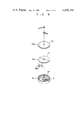
FIGS. 7(a), 7(b), 7(c) show perspective views of other embodiments of the pulse motor;
FIG. 8 shows an exploded view of a major portion of the electronic time keeping device according to the invention;
FIG. 9 shows a cross sectional view of a part of yet another embodiment of the time keeping device according to the invention;
FIG. 10 shows a cross sectional view of a further embodiment of the time keeping device according to the invention;
FIG. 11 shows a front view of the time keeping device which is another embodiment of the invention;
FIG. 12 shows a cross sectional view of the time keeping device shown in FIG. 11; and
FIG. 13 shows perspectively an exploded view of the movement of the time keeping device shown in FIG. 11.
DETAILED DESCRIPTION
The preferred embodiments of the electronic time keeping device will be described in detail with reference to the accompanying drawings.
FIG. 1 to FIG. 3 show one of the preferred embodiments of the present invention as employed in an electronic wrist watch using a 60-pole, 60-step pilse or stepping motor. FIG. 1 shows a cross section of the above electronic wrist watch, where reference numeral 1 denotes an outer casing of the wrist watch with a glass cover 2 fit in its front side opening and a back lid 3 screwed lightly into its rear side opening. Inside the outer casing 1 is located a 60-pole, 60-step pulse motor 4 so that it lies on an insulating base 5 as shown. A circular lower case 6 with an upright peripheral wall 6a on its perimeter is placed under a circular upper case 7 with a round concave or depressed portion 7a at its central part so that the two case members 6, 7 form a casement of the pulse motor. A number of stator segments 8a, . . . are placed vertically at certain intervals along the inner circumference of the annular coil space next inside of the peripheral wall 6a on the lower case 6. Similarly, a number of stator segments 8b, . . . are placed vertically at certain intervals along the same circumference on the lower face of the upper case 7 as the stator segments 8a, . . . are placed along so that the stator segments 8a. . . and the stator segments 8b, . . . are located alternately to form the stator 8 as a whole. An insulating ring 9 is provided around the outer perimeter of the stator 8. The stator coil 10 made of copper wire is wound in the space between the insulating ring 9 and the circular wall 6a of the lower case 6. An annular rotor 11 is located between the stator 8 and the peripheral wall of the concave portion 7a of the upper case 7 so that the rotor 11 is encased by the bottom disc 6 and the top disk 7. The perimeter of the rotor 11 is divided into 60 equal parts which are given magnetic polarities that are north and south alternately. The rotor 11 is mounted on a rotor support 12 fitted to be perpendicular to the pulse motor shaft 13 at the center of the motor 4 as shown. The motor shaaft 13 extends from the center of the lower case 6 through the center of the concave or depressed portion 7a of the upper plate 7 and penetrates a circuit board 15 to be described later, extending upwardly. This shaft is seated on a pivot 14 at the center of the lower case 6 so as to rotate freely. The circuit board 15 which is round and has the same diameter as the upper case 7 is superimposed on the upper case 7 so as to cover the hollow over the concave portion 7a in the casing of the pulse motor. Thus, the circuit board 15 is so located that it forms a lamination with the pulse motor. The circuit board 15 has a printed circuit to perform the time keeping functions one of which is to drive the pulse motor 4. A LSI circuit 16 for the pulse motor 4, a crystal oscillator (not shown) and other electronic components are mounted on that surface of the circuit board 15 which faces the concave portion 7a of the upper case 7. Further, the bearings to hold the shaft of the pulse motor and that of the gears are located on the circuit board 15. That is, a bearing 17 is placed at its center and a bearing 18 is provided near the bearing 17. The bearing 19 is located on the bottom of the concave portion 7a of the upper case 7 so as to make it opposite to the bearing 18. There is a gear 20 in the space between the concave portion 7a of the upper case 7 and the circuit board 15 laid on it. The gear 20 consists of a 1st gear 22 to mesh with a gear 21 formed on the middle of the motor shaft 13, a 2nd gear 23 formed togethe with the 1st gear 22 and 3rd gear (the hour hand gear) 24 to mesh with the 2nd gear 23. The axis of the 1st gear 22 and the gear 23 is in parallel with the motor shaft 13. The shaft of the 1st gear 22 and the 2nd gear 23 is pivoted to rotate freely at the bearing 18 on the circuit board 15 and at the bearing 19 on the concave portion 7a. The motor shaft 13 extending through the circuit board 15 is inserted into the shaft of the 3rd gear 24 but kept free from it to rotate and the 3rd gear is held free to rotate by the bearing 17 on the circuit board 15. That is, the bearing 17 supports the motor shaft 13 and the 3rd gear 24, and the bearing 18 supports the 1st gear 22 and the 2nd gear 23. The minute hand 25 is mounted on the upper end of the motor shaft 13 extending beyond the circuit board 15. The hour hand 26 is mounted on he upper end of the shaft of the 3rd gear 24. In FIG. 1, 27 denotes a dial disc with time numerals and other indicia placed over the circuit board 15, 28 denotes a button battery placed in the insulaing base 5, 29 denotes the lid of the battery space put into the back lid 3, and 30 denotes a flexible lead to connect the battery 28 to the circuit board 15.
The pulse motor 4 shown perspectively and in cross section has the stator 8 of which the segments 8a, --and the segments 8b,--alternatingly turn their magnetic polarities as the direction of the current flow through the coil 10 alters. The rotor 21 comprises 60 equal portions which are alternately different in their magnetic polarities. Thus, pulse signals applied from the drive circuit on the circuit board 25 will rotate the pulse motor 4 stepwise at the rate of one step per minute. The motor shaft 13 makes one revolution in 60 minutes with 60 steps. The motor shaft acting as the shaft of the minute hand directly rotates the minute hand to point the time in minutes. The gear series 20 is to transmit the rotation of the pulsemotor 4 to the hour hand 26. The motion is transmitted from the gear 21 on the motor shaft 13 through the 1st gear 22 and the 2nd gear 23 to the 3rd gear 24 which rotates the hour hand 26 by 5 steps for each hour to indicate the time in hours.
FIG. 3 shows an exploded oblique view of the pulse motor 4 and the circuit board 15. The circuit board 15 with the bearings 17 and 18 in it is superimposed on the pulse motor 4 to make a lamination or layered structure. The bearings 17 and 18 in the circuit board 15 make possible to eliminate the need of at least either the ground plate or the pivotal receptacle plate that are traditionally used to provide the bearing for the motor shaft and gear shafts because they can support these shafts. That is, in consideration of the proximity between the pulse motor 4 and the gear series 20 in terms of location as well as function, the circuit board 15 is superimposed on the pulse motor 4 to form a laination and the circuit board 15 is provided with the bearings 17 and 18 for the motor shaft 13 and the shafts of the gear series in order to make it play the same role as the ground plate or the pivotal receptacle plate. Since circuit board 15 does not pose any restriction in assembly relative to the location of other compnets, it may be aligned with respect to the bearings 17 and 18 as the datum (so as to establish correct position of the motor shaft 13 and the gear shafts). Thus the circuit board 15 can be positioned easily and correctly when it is mounted because no other constraints exist except the positioning of the shafts leaving a wider tolerance for it. Further, in this embodiment, the combination of the concave portion 7a and the circuit board 15 makes it possible to eliminate the need for the ground plate and the pivotal receptacle plate because the motor shaft 13 penetrates the concave portion 7a of the upper case 7 and the bearing 19 is located in it so as to make it function as the ground plate or the pivotal receptacle plate. The use of the 60-pole, 60-step pulse motor 4 with its motor shaft 13 which directly moves the minute hand on it provides a stable time keeping function with high reliability and also makes it possible to eliminate the minute hand portion of the gear series contributing to simplification and miniaturization of the device. Since the pulse motor 4 is provided with the concave portion 7a in the upper case, the gear series 20 and the electronic components of the circuit board 15 can be accommodated in the concave portion as part of the pulse motor, thereby helping design a timepiece even smaller in thickness. In this case, the gear series 20 may be made compact around themotor shaft 13 of the pulse motor 4 and the shafts of the gear series may be pivoted on the upper case 7 of the pulse motor 4.
FIG. 4 shows another embodiment where the pulse motor has a concave portion at its center. There is a channel 35 containing the exciting coil 34 on the periphery of a motor case 33 to cover the rotor 31. Stators 36a and 36b incorporated in the motor case 33 are so placed that they confront the magnet 31a of the rotor 31.
FIG. 5 shows still another embodiment of the pulse motor in which the stator is composed of two parts, one on top of the other, facing a magnet 40a of a rotor 40. Each of the two parts of the stator containing the exciting coils 42a and 42b has a U-shaped cross section made of metal with its edges alternately extending like sawteeth and bent so as to have the tips on one edge come close to those on the other. The number of the tips referred to as 41a1, 41a2, 41b1 and 41b2 is 15 each. The stators 41a1, 41a2, 41b1 and 41b2 are located alternatively and they are 6 degrees apart from each other.
FIG. 6 shows that the concave portion of the pulse motor may be different in shape, position and size depending uppon the components to be placed in it. Thus, the bottom disc 6 may have a concave portion 6c to place the battery 28 in it. It is also possible to have a concave portion 50a in an area other than the center and the periphery of the motor case as shown in FIG. 7(a), to have a concave portion 50b in the area covering the center and the periphery of the motor case as shown in FIG. 7(b), and to have a small concave portion 50c between the center and the periphery of the motor case as shown in FIG. 7(c).
FIG. 8 illustrates another improved embodiment where a motor case 51 has a convex part 52 to engage with a concave part 53a of a circuit board 53 and the concave part 54a of a dial disc 54, thereby permitting easy alignment when they are assembled.
FIG. 9 shows another embodiment of the present invention where a concave portion 56a is provided in the upper part of a pulse motor 56 located below a dial disc 55 so as to place a gear series 57 in the concave portion and the other concave portion 56b is provided in the lower part of the pulse motor so that electronic components 57a and 57b on the circuit board 57 are housed in said concave portion when the circuit board 57 is attached to the bottom of the pulse motor 56 to complete the assembly.
FIG. 10 shows another embodiment when the circuit board is located beneath the pulse motor. A circuit board 62 on which an LSSI package 60 and a crystal oscillator 61 are mounted is placed below a pulse motor 58 with a spacer 59 between the two. It is so designed that a large battery, e.g. lithium battery, 63 is attached to the bottom of a circuit board 62.
FIGS. 11 and 13 illustrate a preferred embodiment of the present invention where the time of day is indicated by the hands of a wrist watch and also by an optical display such as a liquid crystal display an or electrchronic display. FIG. 11 shows a front view of an electronic wrist watch to which this invention is applied.
FIG. 12 shows a cross section of the electronic wrist watch and FIG. 13 is an exploded oblique view of the electronic wrist watch except for the internal gears. The following description will refer to FIGS. 11 to 13 in which reference numeral 100 denotes the casing of the watch whose front end is fitted with a watch glass 101 and whose rear end is fitted with a screwed back lid 103. In the casing 100 is provded a 60-pole, 60-step pulse motor 104 under which a plastic member to form the space for a battery 105 is located. The shape of the pulse motor 104 is the same as the pulse motor 4 shown in FIG. 1. A detailed description of the pulse motor is omitted here. A circuit board 107 is fitted with an LSI 109 which operates the pulse motor 104 and the liquid crystal display 108 to be explained later, the crystal oscillator (not shown) and other electronic components. Output signals to drive the liquid crystal produced by the LSI 109 are transmitted via a flexible wiring sheet 110 and a conductive elastic connector 111 to the liquid crystal display 108, which comprises a front base sheet 112 of transparent galss with an electrode (not shown) formed on it and a rear base sheet 113 of transparent glass with an electrode on it. The front base sheet 112 is laid on a spacer 114, which is placed on the rear base sheet 113, and liquid crystal is sealed inside the space between the sheets 112 and 113. The front base sheet 112 has an opaque coating on its surface except for the date and day of a week display area 112a, an AM display area 112b and a PM display area 112c so that it can serve as the dial disc. The rear base sheet 113 has a reflector (not shown) on its bottom and a clearance hole in it, through which a bearing 115 is located with a spacer 116 at its end to prevent it from touching the liquid crystal and deteriorating the liquid crystal. The liquid crystal display 108 has a clearance hole at its center penetrating the front base sheet 112, a spacer 117 and the rear base sheet 113. A bearing 118 is inserted in the clearance hole so as to allow the hour hand gear shaft 119 to rotate easily. The foregoing design of an electronic wrist watch enables its thickness to be small enough despite the use of the pointers as well as the optical display because it eliminates the need for the ground plate, pivotal receptacle plate and the like that are generally employed in the conventional electronic watches since the liquid crystal display 108 fitted with the bearings 115 and 118 is superposed on the pulse motor 104 with a concave portion to form a lamination so that the gear series and the circuit board 104 are lodged in the concave portion of pulse motor casing. The gear series may well be positioned to fit the gear shafts with the bearings embedded in the liquid crystal display 108. sthus, the assembly of the component parts has been made so simple that all that has to be done is to position the gear series, the circuit board 104 and the flexible wiring sheet 110 on the pulse motor 104 as requied, and place the liquid crystal display 108 followed by mounting of the hour hand and the minute hand.
Although the shaft of the pulse motor is fitted with the minute hand to directly rotate it in all the foregoing embodiments, the present invenion may be applied to a three-hand electronic watch by placing its second hand directly on the motor shaft. Further, the present invention may widely be applied to various electronic time pieces including portable clocks in addition to electronic wrist watches.

Claims (9)

What we claim is:
1. An electronic time keeping device comprising:
an electronic circuit for generating reference clock signals;
a stepping motor coupled to said elctronic circuit and rotatively driven in a stepwise fashion in only one direction by said reference clock signals from said electronic circuit, said stepping motor including: a disc-like hollow motor casing having a recess at the center thereof and an outer peripheral wall surrounding at least said recess, said recess extending inwardly of said motor casing; a coil provided in said hollow motor casing alaong the inner surface of said outer peripheral wall of said motor casing and having a plurality of turns wound in a circumferential direction of said outer peripheral wall; a stator having a plurality of stator segments provided in said hollow motor casing interior of said outer peripheral wall of said motor casing and arranged in said circumferential direction of said outer peripheral wall; and a rotor disposed interior of said stator and having at least a part of said rotor arranged under said recess, whereby said coil, said stator and said rotor are covered by said motor casing and assembled in one unit;
time indicating hands; and
a gear mechanism arranged in said recess of said motor casing and coupled to at least one of said time indicating hands for transmitting rotaion of said rotor of said stepping motor to said at least one of said time indicating hands.
2. The electronic time keeping device of claim 1, wherein said recess extends around the axial center of said disc-like hollow motor casing and terminates spaced from the outer peripheral wall of said hollow motor casing, the portion of said hollow motor casing between said recess and said outer peripheral wall defining an annular ringshaped portion of said hollow motor casing which extends axially of said recess, the innermost wall of said annular ring-shaped portion of said hollow motor casing corresponding to the outermost wall of said recess, said coil and stator segments being provided in said annular ring-shaped portion of said hollow motor casing and said portion of said rotor which is disposed interior of said stator is arranged in said annular ring-shaped portion of said hollow motor casing.
3. The electronic time keeping device of claim 1, wherein electrical parts of said electronic circuit are received in said recess.
4. The electronic time keeping device of claim 1, comprising a shaft coupled to said rotor of said stepping motor; and wherein one of said hands is directly coupled to said shaft.
5. The electronic time keeping device of claim 4, comprising a casing of said time keeping device for receiving said electronic circuit, stepping motor, hands and gear mechanism therein; and wherein the outer diameter of said motor casing of said stepping motor is substantially the same as the inner diameter of said casing of said time keeping device.
6. The electronic time keeping device of claim 1, comprising a casing of said time keeping device for receiving electronic circuit, stepping motor, hands and gear mechanism therein; and wherein the outer diameter of said motor casing of said stepping motor is substantially the same as the inner diameter of said casing of said time keeping device.
7. The electronic time keepingdevice of claim 1, wherein said electronic circuit comprises a circuit board and electronic component parts mounted on said cicuit board; and said circuit board is disposed on the motor casing of said stepping motor.
8. The electronic time keeping device of claim 1, wherein said stator of said stepping motor is formed integrally with said motor casing of said stepping motor.
9. The electronic time keeping device of claim 1, wherein said recess is located interior of said cell, said coil surrounding said recess and extending upwardly of said recess.
US06/366,230 1979-12-06 1982-04-07 Electronic time keeping device Expired - Lifetime US4426159A (en)

Priority Applications (1)

Application Number Priority Date Filing Date Title
US06/366,230 US4426159A (en) 1979-12-06 1982-04-07 Electronic time keeping device

Applications Claiming Priority (2)

Application Number Priority Date Filing Date Title
US10073479A 1979-12-06 1979-12-06
US06/366,230 US4426159A (en) 1979-12-06 1982-04-07 Electronic time keeping device

Related Parent Applications (1)

Application Number Title Priority Date Filing Date
US10073479A Continuation 1979-12-06 1979-12-06

Publications (1)

Publication Number Publication Date
US4426159A true US4426159A (en) 1984-01-17

Family

ID=26797489

Family Applications (1)

Application Number Title Priority Date Filing Date
US06/366,230 Expired - Lifetime US4426159A (en) 1979-12-06 1982-04-07 Electronic time keeping device

Country Status (1)

Country Link
US (1) US4426159A (en)

Cited By (18)

* Cited by examiner, † Cited by third party
Publication number Priority date Publication date Assignee Title
US4908808A (en) * 1987-06-26 1990-03-13 Kinetron B.V. Timepiece having a multipolar rotor
US4984223A (en) * 1987-12-31 1991-01-08 Samsung Electronics Co., Ltd. Analog style electronic watch
US5091771A (en) * 1989-05-15 1992-02-25 Dallas Semiconductor Corporation Compact package for electronic module
FR2690765A1 (en) * 1992-04-30 1993-11-05 Timex Corp Analog movement for timepiece.
US5506991A (en) * 1989-05-15 1996-04-09 Dallas Semiconductor Corporation Printer port adapter with overlaid one-wire interface for electronic key
US5517015A (en) * 1990-11-19 1996-05-14 Dallas Semiconductor Corporation Communication module
US5587955A (en) * 1989-05-15 1996-12-24 Dallas Semiconductor Corporation Electronic token
US5604343A (en) * 1994-05-24 1997-02-18 Dallas Semiconductor Corporation Secure storage of monetary equivalent data systems and processes
US5615130A (en) * 1994-12-14 1997-03-25 Dallas Semiconductor Corp. Systems and methods to gather, store and transfer information from electro/mechanical tools and instruments
US5679944A (en) * 1994-06-15 1997-10-21 Dallas Semiconductor Corporation Portable electronic module having EPROM memory, systems and processes
US5831827A (en) * 1994-04-28 1998-11-03 Dallas Semiconductor Corporation Token shaped module for housing an electronic circuit
US5848541A (en) * 1994-03-30 1998-12-15 Dallas Semiconductor Corporation Electrical/mechanical access control systems
US5994770A (en) * 1991-07-09 1999-11-30 Dallas Semiconductor Corporation Portable electronic data carrier
US6525998B1 (en) * 2001-09-19 2003-02-25 Karen A. Taylor Commemorative timepiece
US6747381B1 (en) * 1998-02-14 2004-06-08 Robert Bosch Gmbh Shaft drive device
CN105322713A (en) * 2014-07-24 2016-02-10 日本电产新宝株式会社 Reduction gear with motor
JP2018009914A (en) * 2016-07-15 2018-01-18 セイコーインスツル株式会社 Mechanism module, movement, and watch
US11119447B2 (en) * 2017-12-08 2021-09-14 Eta Sa Manufacture Horlogere Suisse Timepiece comprising an electric motor fixed to a mounting plate

Cited By (24)

* Cited by examiner, † Cited by third party
Publication number Priority date Publication date Assignee Title
US4908808A (en) * 1987-06-26 1990-03-13 Kinetron B.V. Timepiece having a multipolar rotor
US4984223A (en) * 1987-12-31 1991-01-08 Samsung Electronics Co., Ltd. Analog style electronic watch
US5809519A (en) * 1989-05-15 1998-09-15 Dallas Semiconductor Corporation Systems and methods to convert signals multiplexed on a single wire to three wire
US5506991A (en) * 1989-05-15 1996-04-09 Dallas Semiconductor Corporation Printer port adapter with overlaid one-wire interface for electronic key
US5809518A (en) * 1989-05-15 1998-09-15 Dallas Semiconductor Corporation Command/data transfer protocol for one-wire-bus architecture
US5587955A (en) * 1989-05-15 1996-12-24 Dallas Semiconductor Corporation Electronic token
US5091771A (en) * 1989-05-15 1992-02-25 Dallas Semiconductor Corporation Compact package for electronic module
US5920096A (en) * 1989-05-15 1999-07-06 Dallas Semiconductor, Inc Electrostatic discharge protection systems and methods for electronic tokens
US5834834A (en) * 1989-05-15 1998-11-10 Dallas Semiconductor Corporation Module mounting and adhesion systems and methods for electronic modules
US5627361A (en) * 1989-05-15 1997-05-06 Dallas Semiconductor Corporation Wand for reading and writing information to electronic tokens
US5619066A (en) * 1990-05-15 1997-04-08 Dallas Semiconductor Corporation Memory for an electronic token
US5517015A (en) * 1990-11-19 1996-05-14 Dallas Semiconductor Corporation Communication module
US5994770A (en) * 1991-07-09 1999-11-30 Dallas Semiconductor Corporation Portable electronic data carrier
FR2690765A1 (en) * 1992-04-30 1993-11-05 Timex Corp Analog movement for timepiece.
US5848541A (en) * 1994-03-30 1998-12-15 Dallas Semiconductor Corporation Electrical/mechanical access control systems
US5831827A (en) * 1994-04-28 1998-11-03 Dallas Semiconductor Corporation Token shaped module for housing an electronic circuit
US5604343A (en) * 1994-05-24 1997-02-18 Dallas Semiconductor Corporation Secure storage of monetary equivalent data systems and processes
US5679944A (en) * 1994-06-15 1997-10-21 Dallas Semiconductor Corporation Portable electronic module having EPROM memory, systems and processes
US5615130A (en) * 1994-12-14 1997-03-25 Dallas Semiconductor Corp. Systems and methods to gather, store and transfer information from electro/mechanical tools and instruments
US6747381B1 (en) * 1998-02-14 2004-06-08 Robert Bosch Gmbh Shaft drive device
US6525998B1 (en) * 2001-09-19 2003-02-25 Karen A. Taylor Commemorative timepiece
CN105322713A (en) * 2014-07-24 2016-02-10 日本电产新宝株式会社 Reduction gear with motor
JP2018009914A (en) * 2016-07-15 2018-01-18 セイコーインスツル株式会社 Mechanism module, movement, and watch
US11119447B2 (en) * 2017-12-08 2021-09-14 Eta Sa Manufacture Horlogere Suisse Timepiece comprising an electric motor fixed to a mounting plate

Similar Documents

Publication Publication Date Title
US4426159A (en) Electronic time keeping device
WO2004099884A1 (en) Electronic watch with wireless communication function
US20070097795A1 (en) Timepiece with a calendar function and/or a time setting function, and method of assembling the timepiece
US4376996A (en) Thin stepping motor watch
JP2007121075A (en) Multi-hands watch and standard time radio-controlled multi-hands watch
CN109557797B (en) Gear train device and clock
GB2064831A (en) Electronic time keeping device
JP7195965B2 (en) clock
JP2007121076A (en) Radio-controlled multi-hands watch
JP7087879B2 (en) Movement and electronic clock
JPH01131483A (en) Crystal analog timepiece movement with step motor
US10691078B2 (en) Electronic device and timepiece
JPS6314312B2 (en)
US4335454A (en) Gear train mechanism for a timepiece
JPH0587950A (en) Electronic timepiece
JP2615840B2 (en) Pointer-type world clock
JPS60111178A (en) Pointer display type electronic timepiece
JP7292618B2 (en) Gear train manufacturing method and timepiece manufacturing method
JPH1082871A (en) Timepiece structure
JP2024018180A (en) clock
JPH0618315Y2 (en) Hand clock
JPS626191B2 (en)
JPS6052393B2 (en) Watch gear train structure
JPS58115391A (en) Timepiece
JPS6133388B2 (en)

Legal Events

Date Code Title Description
STCF Information on status: patent grant

Free format text: PATENTED CASE

CC Certificate of correction
MAFP Maintenance fee payment

Free format text: PAYMENT OF MAINTENANCE FEE, 4TH YEAR, PL 96-517 (ORIGINAL EVENT CODE: M170); ENTITY STATUS OF PATENT OWNER: LARGE ENTITY

Year of fee payment: 4

MAFP Maintenance fee payment

Free format text: PAYMENT OF MAINTENANCE FEE, 8TH YEAR, PL 96-517 (ORIGINAL EVENT CODE: M171); ENTITY STATUS OF PATENT OWNER: LARGE ENTITY

Year of fee payment: 8

FEPP Fee payment procedure

Free format text: PAYOR NUMBER ASSIGNED (ORIGINAL EVENT CODE: ASPN); ENTITY STATUS OF PATENT OWNER: LARGE ENTITY

MAFP Maintenance fee payment

Free format text: PAYMENT OF MAINTENANCE FEE, 12TH YEAR, LARGE ENTITY (ORIGINAL EVENT CODE: M185); ENTITY STATUS OF PATENT OWNER: LARGE ENTITY

Year of fee payment: 12