US4423532A - Duster - Google Patents
Duster Download PDFInfo
- Publication number
- US4423532A US4423532A US06/256,835 US25683581A US4423532A US 4423532 A US4423532 A US 4423532A US 25683581 A US25683581 A US 25683581A US 4423532 A US4423532 A US 4423532A
- Authority
- US
- United States
- Prior art keywords
- stem
- thread
- notch
- edge
- band
- Prior art date
- Legal status (The legal status is an assumption and is not a legal conclusion. Google has not performed a legal analysis and makes no representation as to the accuracy of the status listed.)
- Expired - Lifetime
Links
Images


Classifications
-
- B—PERFORMING OPERATIONS; TRANSPORTING
- B25—HAND TOOLS; PORTABLE POWER-DRIVEN TOOLS; MANIPULATORS
- B25G—HANDLES FOR HAND IMPLEMENTS
- B25G3/00—Attaching handles to the implements
- B25G3/02—Socket, tang, or like fixings
- B25G3/12—Locking and securing devices
- B25G3/30—Locking and securing devices comprising screwed sockets or tangs
-
- A—HUMAN NECESSITIES
- A47—FURNITURE; DOMESTIC ARTICLES OR APPLIANCES; COFFEE MILLS; SPICE MILLS; SUCTION CLEANERS IN GENERAL
- A47L—DOMESTIC WASHING OR CLEANING; SUCTION CLEANERS IN GENERAL
- A47L13/00—Implements for cleaning floors, carpets, furniture, walls, or wall coverings
- A47L13/10—Scrubbing; Scouring; Cleaning; Polishing
- A47L13/40—Cleaning implements actuated by electrostatic attraction; Devices for cleaning same; Magnetic cleaning implements
-
- A—HUMAN NECESSITIES
- A47—FURNITURE; DOMESTIC ARTICLES OR APPLIANCES; COFFEE MILLS; SPICE MILLS; SUCTION CLEANERS IN GENERAL
- A47L—DOMESTIC WASHING OR CLEANING; SUCTION CLEANERS IN GENERAL
- A47L13/00—Implements for cleaning floors, carpets, furniture, walls, or wall coverings
- A47L13/10—Scrubbing; Scouring; Cleaning; Polishing
- A47L13/42—Details
Definitions
- This invention relates to a duster, and more particularly to one suitable for capturing fine particle dusts.
- Prior dusters have utilized electrical charging wherein the article is charged with either positive or negative polarity, which causes a strong external electric field to be established which often gives an unpleasant feeling to a user.
- an improvement has been developed in an electret system.
- This electret system is the so called "permanent electric polarization" in which the article, once having been charged, maintains a bipolar charged condition semi-permanently or perpetually thereby producing only a small external electric field.
- no unpleasant feeling is given to a user due to the electric charge.
- the charges are not transmitted to the dusts, the latter of which seldom fall down, but which nevertheless are recapturable even should they fall.
- This invention provides the dusters employing the electret system with a simple design and easy fabrication which assures dust capture.
- Polyolefin resin film such as polyethylene or polypropylene, or any other convenient chemical providing equivalent characteristics, may be used for the duster material.
- a primary aspect of this invention relates to a duster comprising a cylindrical stem with a continuous radial thread extending from its tip towards a root portion spaced along the stem.
- a band of material is formed from a plurality of bundles of fibers or fibrils made from a ductile synthetic resin film, which has been charged to the electret state, split into yarns and crimped. The bundles are arranged in a meandering manner. One edge of the band comprises loose ends, the other edge being held together by one or more strings.
- the material is wound around the radial thread, the tip end of which is engaged with a supporting member and the other end of which is provided with a notch at the root portion of the stem.
- the duster further comprises a grip which is mated and/or threadably secured to the root portion of said stem.
- FIG. 1 is an elevational view partially in section of a duster according to a preferred embodiment of this invention
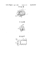
- FIG. 2 is a perspective view of the stem portion of the duster shown in FIG. 1;
- FIG. 3 is a perspective view of a supporting member utilized with the embodiment of FIG. 1;
- FIG. 4 is a perspective view of the grip portion of the duster shown in FIG. 1;
- FIG. 5 is an enlarged sectional view of the supporting member shown in FIG. 3;
- FIG. 6 is a view taken along line A--A in FIG. 5;
- FIG. 7 is a view taken along line B--B of FIG. 5;
- FIG. 8 is an enlarged front view of the supporting member shown in FIG. 3;
- FIGS. 9 and 10 are perspective views illustrating how fabric is attached to the supporting member
- FIG. 11 is a sectional view of the supporting member illustrating how the fabric material is attached thereto;
- FIGS. 12-14 are enlarged perspective, front and sectional views showing an alternative embodiment of the invention.
- FIGS. 15-17 are enlarged perspective, front and sectional views of a still further embodiment of the invention.
- FIG. 18 is a perspective view of a fabric suitable for use with the invention.
- FIG. 19 is a perspective view of a modified stem portion of a duster
- FIG. 20 is an enlarged side elevational view of the forward end of the stem shown in FIG. 19;
- FIG. 21 is a sectional view taken along line C--C in FIG. 20;
- FIG. 22 is a sectional view taken along line D--D in FIG. 19;
- FIG. 23 is a perspective view of the grip utilized in conjunction with the stem shown in FIG. 19;
- FIG. 24 is a sectional view of a modified duster utilizing the components shown in FIGS. 18-23;
- FIG. 25 is a perspective view of a still further modification of the stem portion of a duster
- FIG. 26 is an enlarged fragmented elevational view of the tip end of the stem shown in FIG. 25;
- FIG. 27 is a sectional view taken along line E--E in FIG. 26;
- FIG. 28 is an enlarged sectional view taken along line F--F in FIG. 25;
- FIG. 29 is an enlarged sectional view taken along line G--G in FIG. 25;
- FIG. 30 is a perspective view of a still further modification of the stem portion of a duster
- FIG. 31 is an enlarged sectional view taken along line H--H in FIG. 30.
- FIG. 32 is an enlarged sectional view taken along line I--I in FIG. 30.
- Synthetic resin film of the type identified above when elongated or stretched to the maximum becomes extremely thin film or foil and has remarkable tensile strength.
- This foil is moved longitudinally onto a needle roller and/or a roller with thin blades or pins to produce a plurality of thin slits, creating bundles of continuous fine fibers or fibrils.
- This treatment or operation is called “splitting-fibers or fiber-splitting”.
- the thus treated film is then subjected to a heat-treatment and given a crape to become crimped thereby producing a soft-touch texture having a combined effect in the finely divided or split fibrillated film which is similar to feathers.
- This invention provides dusters employing the electret system with fibers split and crimped so as to achieve a simple design having highly improved dust capturing efficiency.
- a primary aspect of this invention is a duster comprising a cylindrical stem 5 (FIG. 2) with a continuous thread 6 extending from a forward tip end towards a root portion spaced from the opposite end of the stem 5.
- a grip 18 threadably mates with the root portion of said stem 5, said root portion being provided with an engaging or fixture means having a generally L-shaped notch or slit 12 for securing split and crimped yarn bundles 1 of ductile synthetic resin which have been electrically charged, each of which is arranged in a meandering manner with one edge being engaged with one or more strings formed in a loop 2 to produce a fabric material 4.
- the tip end portion of the stem is provided with an opening extending between the side portions of said stem 5.
- the depth of said opening reaches a position beyond the center of said stem 5 where it narrows for the remaining width portion of the stem.
- One end of the fabric material 4 is inserted into said opening above its thread-engaged edge with a portion of the fabric being wound about itself (FIG. 11).
- the remaining material extends from said wound portion through the narrowed opening and is wound about the thread 6 formed on the circumferential wall of the stem 5.
- a terminal end of said material 4 is forcibly inserted within the generally L-shaped notch 12 provided on said root end of the stem 5 thereby permitting a secure fixing thereof.
- FIGS. 1 and 9 show a plurality of fiber bundles 1 made of polyolefin synthetic resin film which has been stretched to its maximum elongation to form a thin film, charged to the electret state, split into fibers and crimped.
- These yarn bundles 1 are arranged in a meandering manner and are, as shown in FIG. 9, of a predetermined length with the bundles in adjacent rows being formed to contact each other. At one side, the ends of the fibers are loose, while at the other loops 2 are knitted or sewn together with one or more strings 3 to form a fabric material 4 of predetermined length and width.
- a cylindrical member 7 protrudes from a forward tip end of the stem 5, and the radius of the member 7 is smaller than that of the stem 5.
- An annular ridge 8 is formed around the circumferential wall of the member 7 intermediate its ends.
- a generally straight recess 9 extending axially thereof and traversing the ridge thereon.
- the recess serves as a positioning member for the support member 16 which will be discussed later in detail.
- FIG. 2 shows the stem 5 being formed near the root portion of thread 6 with a generally semi-circularly formed D-shaped cut 10 to define identical plane platforms or steps 10a on the stem.
- a generally L-shaped curved notch 12 extends from steps 10a axially of the stem 5 at its center.
- a male thread 13 having a relatively larger diameter than thread 6.
- the thread 13 is sandwiched between the D-cut and a mating member 14 having plane surfaces 14a at its opposite side walls.
- Member 14 also defines an annular ridge 15 on the stem.
- FIG. 3 shows a supporting member 16 having a threaded portion 6a corresponding to the radial thread 6 on the stem 5.
- This member 16 is formed at its threaded end with a ridge 16a (FIG. 6) on its inner circumferential wall which is matable with the recess 9 of the cylindrical member 7 previously discussed.
- a front plate 17 Formed at the end of said support 16 forwardly of thread 6a is a front plate 17 covering said support.
- the plate 17 has a generally U- or V-shaped notch or slit 17a, an inner end of which merges with a narrower notch 17b, which in turn connects with still another notch 17c formed of a predetermined axial length along the support 16.
- a generally semi-circular opening 17d (FIG. 5) which faces notch 17a and communicates with a further notch 17e formed along the length of support member 16.
- annular recess 17f is formed in the inner-circumferential wall of the support 16 at the end thereof opposite plate 17. This recess receives the annular ridge 8 formed on the circumferential wall of the cylindrical member 7 of the stem 5.
- the support 16 has a semicylindrical thick member 17g on a side of member 16 opposite to the side where opening 17e is formed.
- the cross sectional view in FIG. 11 illustrates an arcuate notch 17h formed opposite to the notch 17e of this semi-cylindrical member 17g and its radius is larger than that of the inner end of notch 17a.
- These notches 17b, 17c are formed transversely across the semicylindrical member 17g.
- arcuate side walls 17i Extending from both ends of said semi-circular member 17g along the circumferential outer wall of the support 16 are arcuate side walls 17i (FIGS. 5 and 7) the tip ends of which define said opening 17e and the upper end rims of each of which define an arcuate opening at a lower surface of said front plate 17.
- These arcuate side walls 17i, 17i, the semiarcuate cylindrical member 17g and the front plate 17 define an inner space 17j.
- Support 16 after positioning its ridge 16a within the recess 9, is pressed against the front surface of the tip end 7 of the stem 5, and it is secured to the stem due to the mating of the ridge 8 within the recess 17f.
- the open end of the U-shaped notch 17a faces oppositely to the ridge 11 formed on the root portion of the stem 5.
- a grip 18 (FIGS. 1 and 4) is formed in a cylindrical shape with a forward tip end portion 19 having a bell shape around the inner circumferential wall of which is formed a thread 19a. This thread mates with thread 13 formed on the root portion of the stem 5.
- the inner diameter of the cylindrical portion of grip 18 is nearly equal to the diameter of the arcuate faces of member 14 formed at the opposite end of said stem 5 from member 7.
- An annular recess 18a is provided on an inner circumferential wall of grip 18 near the bell 19 for mating with ridge 15 on stem 5 when the grip 18 is completely threadably mated with the stem by means of screws 13 and 19a.
- the support 16 is first joined to member 7 at the tip end of the stem 5, as previously described.
- bundles of the material 4 are tightly rolled together (FIG. 11) such that a diameter of the edge which has been spirally sewn, stitched or knitted with the strings 2 will be larger than the width of the notch 17e provided on the support 16 when the roll relaxes.
- the edge engaged (sewn, stitched or knitted) with strings 2, with the aid of notches 17e and 17a, is forcibly inserted within the space 17j formed between the front plate 17 and the circumferential support walls.
- the fabric material 4 extending from that spirally wound within space 17j passes outwardly from the support 16 through the notches 17b and 17c and the edge engaged by the strings 2 is wound around support 16 along the thread 6a formed on the circumferential wall of the support 16.
- the material 4 wound around the thread 6a presses material 4 within the notch 17d against the semi-circular cylindrical member 17g. Accordingly, it prevents the material 4 from coming out of the space 17j in the support.
- the portion with the notch 17e and having no thread 6a also serves to hold the material 4 within the inside of the support 16.
- the continuity of thread 6a on the support 16 with thread 6 of the stem 5 permits the material 4 to continue to be wound along stem 5 from the support 16.
- the material 4 after being wound onto the thread 6 is forcibly inserted within the curved narrow space of the L-shaped notch 12 and is fixed therein.
- the grip 18 is screwed onto the stem 5, whereupon the annular ridge 15 formed on portion 14 of the stem 5 is mated within the recess 18a formed on the inner circumferential wall of the grip 18 (FIG. 1).
- An opening 18b (FIG. 4) is formed at the rear end of the grip 18 for hanging it on a hook.
- the duster which has been described permits the fibers or fibrils of the fabric material 4 to spread radially from the tip end of the stem 5 with the aid of the support 16, and its appearance is not only aesthetic and elegant, but also the end of the support 16 is never exposed and hence the duster never damages furniture during cleaning.
- FIGS. 12-14 illustrate a modification of the support 16 in that it is designed integral with the stem 5. It is formed with a U-shaped space 20 at the tip end of the stem 5 open at the side. A front plate 21 is located at the forwardmost part of the tip end, and a notch 21a having a width narrower than said space 20 is provided in the front plate 21 in communication with said space 20. A notch 21b formed in the front plate 21 communicates with both the space 20 and the notch 21a.
- the modified duster also permits the fibers or fibrils of material 4 to protrude from the stem 5 tip end in a manner similar to the support 16 previously discussed. Since the open side of the space 20 is sealed when the material 4 is wound around the thread 6, the material contained in space 20 can not come out outwardly.
- the notch 21a having a width narrower than the width of the space 20 prevents the material contained within the space 20 from coming out of the notch 21a.
- FIGS. 15-17 illustrate a further modification of the support similar to the embodiment shown in FIGS. 7-12.
- this support has an internal space 22 open at the side of the stem 5, the space 22 extends forwardly to open at the forward tip end of the stem 5.
- a pair of steps 23 having semi-circular cross sections are provided in spaced relationship intermediate the ends of the inner circumferential wall of space 20. The width of the space 22 is narrowed where these steps 23 are positioned.
- a notch 22a is formed on the forward tip end of the stem 5 so as to communicate with the space 22.
- the thus designed stem permits the material 4 compressed in space 22 to protrude from the tip end of the stem 5 in a manner such that a portion of the material 4 is pressed between the projections 23 assuring that the material 4 does not escape from the tip end of the stem 5. Since the side opening of the space 22 is sealed when the material is wound along the thread 6, the material contained within the space 22 can not move sidewardly out of the space. In the modifications shown in FIGS. 12 and 15, the bottoms of spaces 20, 22 are, of course, closed or sealed.
- this invention provides dusters which have designs wherein the tip ends of the stems 5 are open at their sides to form internal open spaces. Narrowed openings are provided at the tip ends of the stems 5 in communication with their respective internal spaces to contain fabric material 4 wound within the spaces. The ends of the material 4 protrude from the stem tip end so that the forward tip end of the stem 5 is never exposed. Dusters made in accordance with this invention offer an elegant appearance and prevent damage to furniture during cleaning. The invention permits easy fabrication of the dusters since the attachment of the material 4 is quite easily made.
- FIGS. 18-24 A still further modification of the invention is illustrated in FIGS. 18-24.
- the duster shown has a cylindrical hollow stem 105 with a continuous thread 107 extending from its forward tip end to a position intermediate the end of the duster.
- a large diameter annular ring 109 having at least one recess or thread 109a around its outer circumferential wall is provided.
- At opposite sides of the annular ring 109 are means for mating a grip 111 and the fabric material 104, respectively.
- the grip 111 is mated to portion 110 by a detachably threaded relationship with the thread 109a on the ring 109.
- the fabric material 104 made of the ductile synthetic resin film is charged to the electret state, fiber-split and then crimped into a plurality of rows of fiber or fibril bundles 101 arranged in a meandering manner in a band-like shape.
- the bundles 101 are cut at one end while being engaged at the opposite end in any convenient manner (e.g., by being sewn, knitted or stitched) with one or more coil strings 103, leaving loops 102.
- the forward tip end of stem 105 comprises an integral plate piece 106 formed on said stem 105.
- Plate 106 is formed with a notch 106a, which has a generally L-shape or V-shape extending from its forward end along the axial direction of the stem.
- the stem 105 has an upright ridge 108 extending along the axial direction of the stem adjacent the end of the thread 107.
- a further notch having a generally L- or V-shaped form when viewed from the side of the stem 105, is provided on ridge 108.
- One edge of said material 104 held together by the strings 103 is continuously wound around the stem within the thread 107.
- One end of said material 104 is sandwiched within the notch 106a of the plate piece 106, and the opposite end is sandwiched within the notch 108a of the ridge 108.
- a still further modification as shown in FIGS. 25-29, comprises a duster having a hollow cylindrical stem 205 with a continuous thread 207 extending from its forward tip end to a position intermediate the end of the duster. In the vicinity of the end of the thread, a plurality of ridges 209 are formed to extend along the axial direction of the stem. These ridges are spaced equally around the circumferential wall of portion 210 of the stem.
- the duster has a grip (not shown, but identical with the numeral 111 in FIG. 23) which is detachably and forcibly inserted onto said stem over said ridges 209.
- a fabric material 104 (FIG.
- a plate 206 is formed integral with the forward tip end of said stem 205, and plate 206 is provided with a generally L- or V-shaped notch or slit 206a extending inwardly.
- stem 205 is provided with a ridge plate 108 extending axially of the stem, said plate 208 being provided with a notch 208a of generally L- or V-shaped form directed inwardly from the side of the plate.
- the material 104 along the edge engaged by said coil strings 103 is continuously wound around and within said thread 207 of the stem 205. A forward end of said material is sandwiched within said notch 206a of the plate 206, and the rear end is sandwiched within said notch 208a of the ridge 208.
- a still further modification shown in FIGS. 30-32, has a hollow cylindrical stem 305 with an integral front plate 306 formed at its forward tip end and is provided with a continuous thread 307 from the tip end to the center of the stem.
- a grip 310 extends from the center of the stem towards the rear in an axial direction. The grip has a larger diameter than the stem.
- a fabric material (identical with that designated 104 in FIG. 18) is made of ductile synthetic resin film which has been charged to an electret state, fiber-split and then crimped to produce a plurality of fiber or fibril bundles (identical with those designated 101 in FIG. 18) arranged in a meandering manner.
- Plate 306 is provided with a generally L- or V-shaped notch or slit 306a extending from its forward end along the axial direction of the stem, and there is provided, adjacent the end of the thread on said stem 305, an axially extending ridge 308, in which is formed a generally L- or V-shaped formed slit 308a directed downwardly from the upper edge of the slit.
- the material 104 along an edge engaged by strings 103 is wound around and within thread 307, its forward end being sandwiched within said notch 306a of the front plate 306, and its rear end being sandwiched within said notch 308a of the ridge 308.
- the duster has its stem formed with a thread on its circumferential wall, and its grip is threadably mated with a thread formed on a larger diameter circumference of the stem.
- the one edge of the fabric material engaged by coiled string and which is made of ductile synthetic resin film, charged to the electret state, fiber-split and crimped, is continuously wound around and within the thread on the stem to offer simple and easy fabrication.
- the grip which is threadably engaged is only detachable upon rotation, and it is never pulled out by an external force during dusting. However, it is easily detachable when desired to permit the easy exchange of the duster portion.
- the stem has, at the ends of its threaded portion, generally L- or V-shaped notches or slits which have two triangular projections in cross section at positions opposite to inner faces of said notches so as to narrow the notch widths.
- This construction permits easy attachment of the fabric material by sandwiching the material in the notches. The material thus is securely fixed therein without chance of escaping therefrom since the material is sandwiched between opposite projections and also is folded toward the deepest portions of the L- or V-shaped notches.
Abstract
Description
Claims (2)
Priority Applications (1)
| Application Number | Priority Date | Filing Date | Title |
|---|---|---|---|
| US06/256,835 US4423532A (en) | 1981-04-23 | 1981-04-23 | Duster |
Applications Claiming Priority (1)
| Application Number | Priority Date | Filing Date | Title |
|---|---|---|---|
| US06/256,835 US4423532A (en) | 1981-04-23 | 1981-04-23 | Duster |
Publications (1)
| Publication Number | Publication Date |
|---|---|
| US4423532A true US4423532A (en) | 1984-01-03 |
Family
ID=22973784
Family Applications (1)
| Application Number | Title | Priority Date | Filing Date |
|---|---|---|---|
| US06/256,835 Expired - Lifetime US4423532A (en) | 1981-04-23 | 1981-04-23 | Duster |
Country Status (1)
| Country | Link |
|---|---|
| US (1) | US4423532A (en) |
Cited By (10)
| Publication number | Priority date | Publication date | Assignee | Title |
|---|---|---|---|---|
| WO1999062371A1 (en) * | 1998-06-05 | 1999-12-09 | E.I. Du Pont De Nemours And Company | Monofilament bristle assemblies and methods of making brushes using same |
| US6096151A (en) * | 1998-06-05 | 2000-08-01 | E. I. Du Pont De Nemours And Company | Method and apparatus for making articles having bristles |
| US6351868B1 (en) | 1998-06-05 | 2002-03-05 | E.I. Dupont De Nemours & Company | Bristle sub-assemblies having parallel pairs of bristles; and methods |
| US6543083B1 (en) | 1998-06-05 | 2003-04-08 | E. I. Du Pont De Nemours & Co. | Bristles having varying stiffness |
| US20030221271A1 (en) * | 1998-06-05 | 2003-12-04 | Edwards Mark Stephen | Bristle sub-assemblies and method of making same |
| US20040216255A1 (en) * | 2001-12-03 | 2004-11-04 | Daegon Nam | Hand tool for cleaning |
| US20050177967A1 (en) * | 2000-07-10 | 2005-08-18 | Uni-Charm Corporation | Cleaning article |
| WO2007103625A1 (en) * | 2006-03-06 | 2007-09-13 | Casabella Holdings, Llc | Microfiber duster |
| US9248974B2 (en) | 2013-03-08 | 2016-02-02 | Mark S. Grill | Cleaning apparatus, methods of making cleaning apparatus, and methods of cleaning |
| US20190224554A1 (en) * | 2018-01-21 | 2019-07-25 | Richard West | Quarterback training device |
-
1981
- 1981-04-23 US US06/256,835 patent/US4423532A/en not_active Expired - Lifetime
Cited By (18)
| Publication number | Priority date | Publication date | Assignee | Title |
|---|---|---|---|---|
| US20030116258A1 (en) * | 1998-06-05 | 2003-06-26 | Edwards Mark Stephen | Method and apparatus for making articles having bristles |
| US6269514B1 (en) | 1998-06-05 | 2001-08-07 | Du Pont | Monofilament bristle assemblies and methods of making brushes using same |
| US20030221271A1 (en) * | 1998-06-05 | 2003-12-04 | Edwards Mark Stephen | Bristle sub-assemblies and method of making same |
| WO1999062371A1 (en) * | 1998-06-05 | 1999-12-09 | E.I. Du Pont De Nemours And Company | Monofilament bristle assemblies and methods of making brushes using same |
| US6434778B1 (en) | 1998-06-05 | 2002-08-20 | E. I. Du Pont De Nemours And Company | Monofilament bristle assemblies and methods of making brushes using same |
| US6543083B1 (en) | 1998-06-05 | 2003-04-08 | E. I. Du Pont De Nemours & Co. | Bristles having varying stiffness |
| US20030115708A1 (en) * | 1998-06-05 | 2003-06-26 | Edwards Mark Stephen | Method and apparatus for making articles having bristles |
| US20030115703A1 (en) * | 1998-06-05 | 2003-06-26 | Edwards Mark Stephen | Bristles having varying stiffness |
| US6351868B1 (en) | 1998-06-05 | 2002-03-05 | E.I. Dupont De Nemours & Company | Bristle sub-assemblies having parallel pairs of bristles; and methods |
| US6096151A (en) * | 1998-06-05 | 2000-08-01 | E. I. Du Pont De Nemours And Company | Method and apparatus for making articles having bristles |
| US20050177967A1 (en) * | 2000-07-10 | 2005-08-18 | Uni-Charm Corporation | Cleaning article |
| US7302730B2 (en) * | 2000-07-10 | 2007-12-04 | Uni - Charm Corporation | Cleaning article |
| US6928688B2 (en) * | 2001-12-03 | 2005-08-16 | Daegon Nam | Hand tool for cleaning |
| US20040216255A1 (en) * | 2001-12-03 | 2004-11-04 | Daegon Nam | Hand tool for cleaning |
| WO2007103625A1 (en) * | 2006-03-06 | 2007-09-13 | Casabella Holdings, Llc | Microfiber duster |
| US20090123725A1 (en) * | 2006-03-06 | 2009-05-14 | Txf Products, Inc. | Microfiber duster |
| US9248974B2 (en) | 2013-03-08 | 2016-02-02 | Mark S. Grill | Cleaning apparatus, methods of making cleaning apparatus, and methods of cleaning |
| US20190224554A1 (en) * | 2018-01-21 | 2019-07-25 | Richard West | Quarterback training device |
Similar Documents
| Publication | Publication Date | Title |
|---|---|---|
| US4423532A (en) | Duster | |
| US5240295A (en) | Knot tying device | |
| US8061368B2 (en) | Hair holder with elastic friction member | |
| CA2086944C (en) | Wraparound closure device | |
| DE4036834A1 (en) | TIE DEVICE FOR MAINS CONNECTION CORDS | |
| US4483339A (en) | Vascular surgery roll | |
| US2429176A (en) | Hair curler | |
| US3533418A (en) | Self anchoring hair curler | |
| US3854767A (en) | Rope assembly | |
| CA1103120A (en) | Hair-curler | |
| US2254816A (en) | Hair curler | |
| JPS5925215Y2 (en) | Slide fastener tape | |
| JPS6132619Y2 (en) | ||
| EP0032871B1 (en) | Process for manufacturing an elastic knitted tape on a raschel or warp-knitting machine and the tapes manufactured by this process | |
| JPS6132616Y2 (en) | ||
| JPS6132618Y2 (en) | ||
| JPS6132617Y2 (en) | ||
| JP2919344B2 (en) | Spool device for line such as fishing line | |
| JP7114181B2 (en) | water absorbing umbrella bag | |
| JPH034199Y2 (en) | ||
| JP3946035B2 (en) | Tearable core member and cold shrink tube device having the core member | |
| JPH0127655Y2 (en) | ||
| JPS6338829Y2 (en) | ||
| KR200244348Y1 (en) | chenille yarn | |
| US4835901A (en) | Fishing hook-leader holder |
Legal Events
| Date | Code | Title | Description |
|---|---|---|---|
| AS | Assignment |
Owner name: DUSKIN FRANCHISE KABUSHIKI KAISHA (D/B/A DUSKIN FR Free format text: ASSIGNMENT OF ASSIGNORS INTEREST.;ASSIGNORS:YAGI, AKIRA;NISHIMURA, HARUO;BANDAI, SHINJI;AND OTHERS;REEL/FRAME:004088/0729 Effective date: 19810421 |
|
| STCF | Information on status: patent grant |
Free format text: PATENTED CASE |
|
| MAFP | Maintenance fee payment |
Free format text: PAYMENT OF MAINTENANCE FEE, 4TH YEAR, PL 96-517 (ORIGINAL EVENT CODE: M170); ENTITY STATUS OF PATENT OWNER: LARGE ENTITY Year of fee payment: 4 |
|
| MAFP | Maintenance fee payment |
Free format text: PAYMENT OF MAINTENANCE FEE, 8TH YEAR, PL 96-517 (ORIGINAL EVENT CODE: M171); ENTITY STATUS OF PATENT OWNER: LARGE ENTITY Year of fee payment: 8 |
|
| FEPP | Fee payment procedure |
Free format text: PAYOR NUMBER ASSIGNED (ORIGINAL EVENT CODE: ASPN); ENTITY STATUS OF PATENT OWNER: LARGE ENTITY |
|
| MAFP | Maintenance fee payment |
Free format text: PAYMENT OF MAINTENANCE FEE, 12TH YEAR, LARGE ENTITY (ORIGINAL EVENT CODE: M185); ENTITY STATUS OF PATENT OWNER: LARGE ENTITY Year of fee payment: 12 |